background image


  Operation and Maintenance Manual 


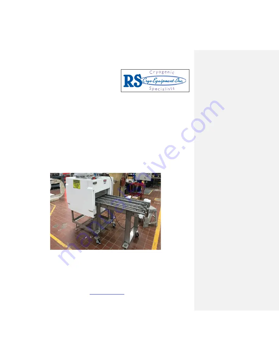
COMPACT FREEZE TUNNEL® 

Liquid Nitrogen Cryogenic Freezer 


For service or support, please call:


RS CRYO EQUIPMENT, INC.


629 Grove Street Manteno, IL 60950 Phone: (815) 468

6115, Fax: (815) 468

2651


http://www.rscryo.com


Summary of Contents for COMPACT FREEZE TUNNEL

Page 1: ...tenance Manual COMPACT FREEZE TUNNEL Liquid Nitrogen Cryogenic Freezer For service or support please call RS CRYO EQUIPMENT INC 629 Grove Street Manteno IL 60950 Phone 815 468 6115 Fax 815 468 2651 ht...

Page 2: ...1 3 8 Temperature Control System 11 4 Installation Assembly 12 4 1 Site SelectionRequirements 12 4 2 Unloading the Compact Freezer 13 4 3 Positioning the Freezer 13 4 4 Connecting Freezer Sections and...

Page 3: ...9 3 Conveyor and Conveyor Drive 35 9 4 Safety Relief Valves 36 9 5 Module Joints 36 9 6 Solenoid Valves 36 9 7 Strainer 36 9 8 Doors 36 9 9 Headers and Orifices 37 9 10 Temperature Controller 38 9 11...

Page 4: ...re that all separately packed items exhaust spare parts bolts etc have beenreceived If there is any damage all claims must be made promptly to the shipping company The RS Cryo Equipment representative...

Page 5: ...llows humid air into the freezer and may cause the system to freeze up Never reach inside the freezer when it is running Doing so may result in bodily injury from cold burns Never leave the freezer un...

Page 6: ...o ensure the proper removal of nitrogen vapor To re start freezer turn the fan conveyor and instrument power buttons to the off position Once all three are OFF then turn each back to the on position F...

Page 7: ...to increase Unless this pressure can bleed back into the supply tank or out a safety relief valve it may burst the line Safety relief valves should be piped to an outside area Always open valves slow...

Page 8: ...OPERATION MAINTENANCE MANUAL CompactFreezer 7 3 About the Compact Freezer 3 1 EQUIPMENT SPECIFICATIONS COMPACT FREEZER FREEZER MODULES LENGTH 1 83 2 122 3 161 38 38 7 40 48 120V SINGLE PHASE 35AMP...

Page 9: ...duct heat load If the product flow stops the freezer automatically reduces the liquid nitrogen injection rate to the minimum required to maintain the freezer operating set point temperature A key erro...

Page 10: ...OPERATION MAINTENANCE MANUAL CompactFreezer 9 warm outer surfaces of the parts to keep cooling losses to a minimum All fasteners...

Page 11: ...erials approved by inspection agencies for use as food contact surfaces The upper and lower doors open on each side of the freezer to fully expose the inside for ease of cleaning 3 4 CONVEYOR S BELT S...

Page 12: ...n motor push button station 1 per freezer for variable speedfans 2 Conveyor drive push button station 1 per drive 3 Instrument power push button station 4 Exhaust blowers push button station 5 Tempera...

Page 13: ...hat require the use of extension headers have piping run to either the preceding or following module with a duplicate header system in those modules For optimal freezing capacity the Compact Freezer t...

Page 14: ...fully map out the path to the installation area prior to unloading the Compact Freezer from the truck Determine the most suitable freezer orientation to pass through all bottle necks and to assure cor...

Page 15: ...r must be unloaded by means of a crane or forklift The recommended means of transport is on industrial rollers if a crane or forklift can not be used Ensure that the total weight of the freezer does n...

Page 16: ...end only The first module of the second crate should be positioned to extend about 2 onto the exposed pedestal half mounting surface F Uncrate the modules G Coat to inner mating surface of modules wi...

Page 17: ...drive sprockets teeth areengaged Install scraper belt at exit end of top belt and adjust it just short of touching the bet Do the same for exit chute on bottom belt 4 6 LEVELING THE FREEZER The freeze...

Page 18: ...e installation drawing for each blower mounting is forwarded to the customer to pass on to his installation contractor who is normally responsible for mounting and connecting the exhaust to the trough...

Page 19: ...cation of the controller and shielded wire should be as remote as possible relative to any AFC generating unit controller to prevent pick up of RF noise Six inches is tooclose 1 Earth Ground Earth gro...

Page 20: ...source of liquid nitrogen from a storage tank The liquid nitrogen supply piping connects the storage tank with the liquid nitrogen injection system of the freezer Insulate all liquid nitrogen piping u...

Page 21: ...his will allow for proper exhaust system performance and reduce negative pressure in the production area Protect the exit of the exhaust system against bad weather conditions and or birds Minimize the...

Page 22: ...ezer Room air can bring moisture into the freezer therefore affecting the efficiency and economical operation of the freezer 6 Initial Start up and Tuning The Cabinet Freezer was factory tested before...

Page 23: ...control panel are OFF 9 With the main disconnect in the OFF position use a multi meter to check that the proper voltages and amperage is supplied to the control panel 10 Open the main shut off valve a...

Page 24: ...nveyor at approximately a 45 angle 6 3 OPERATING TEMPERATURE The normal operating temperature of the Cabinet Freezer tunnel can be adjusted from 50 F to 125 F 10 C to 120 5 C for most products for opt...

Page 25: ...slowest speed that will handle the required production and then increase the freezer operating temperature to the warmest temperature that will produce the desired results This is the most economical...

Page 26: ...e running daily 2 Check solenoid valve operation at least weekly 3 Check conveyor belt slack frequently 4 Change conveyor drive gear box oil as specified in component manual 7 2 DAILY START UP AND OPE...

Page 27: ...king the residence time The speed of the in feed and discharge conveyors should be matched to assure a smooth product transfer 10 Check that the liquid nitrogen is injecting into the freezer This star...

Page 28: ...he conveyor In this case the temporary shutdown would be to turn off instrument power the fans and the conveyor C Three or four minutes before restarting production start the fan motors and conveyors...

Page 29: ...e frozen shell Equilibration occurs in the package where the refrigeration of all pieces compliments eachother 7 6 SHUTDOWN At the end of a production shift the freezer should be shut down in the foll...

Page 30: ...rotect electrical components from water moisture damage with plastic bags if possible Wear gloves and safety glasses to avoid personal injury from high pressure hot water or steam jets Remove or secur...

Page 31: ...freezer as dry as possible It is recommended that with all power off both the upper and lower doors be left open until the next productionshift 10 Any removable parts that were taken off the freezer...

Page 32: ...l accessory not included with allunits 9 2 CONVEYOR AND CONVEYOR DRIVE Conveyor Belt Inspect the belt daily for the first several days of operations and semi monthly afterwards A tensioning device is...

Page 33: ...conditions Conveyor Drive Gear Reducer Change oil after every 1 000 hours of operation Use Mobil 600W cylinder oil or equivalent 9 3 SAFETY RELIEF VALVES Safety Relief Valves should be located between...

Page 34: ...hold down strip and screws Do not force the screwstight Door Safety Switch The adjustment of the door safety switch actuation is done in the followingsequence 1 Make sure power is turned OFF 2 Loosen...

Page 35: ...tion The lower limit set point is programmed to not exceed 125 F 130 C but can be reprogrammed for warmer or colder limits if the situation warrants it Control functions alarm settings and other param...

Page 36: ...rom inside the apparatus box and free the cable 2 Remove fan blade by first loosening the two cross bolts on it Remove hex cap screw and thrust washer and slide fan blade and key off the shaft 3 Remov...

Page 37: ...z electrical power supply Use the electrical schematic in Appendix B Reference Drawings for more information with respect to the voltage requirements and other specifications The variation in supply v...

Page 38: ...order Check if the emergency stops have been activated Reset if necessary Check if the main fuses of the drive motor belt are intact If the conveyor belt does not run at a smooth uniform speed check...

Page 39: ...jection of LN2 Reduce number of nozzles in sensor area Valve may need throttling Reduce pressure of tank Injection too close to sensor Change location of nozzle Ice build up around nozzle causing dire...

Page 40: ...ce each if necessary Jammed conveyor belt motor hums Press the E stop button check for jam and correct cause Belt drive not activated Activate belt drive Emergency stop is activated Pull to reset the...

Page 41: ...speed Exhaust fan not running Exhaust system not switched on Activate exhaust system Circuit breaker of motor failed Reset breaker No LN2 injection LN2 injection not activated Start LN2 injection Tank...

Page 42: ...Shaft Fan 30 570263 Coupling Fan Shaft Split 5 8 I D 30 570354 Bearing Fan Shaft 30 550561 Sleeve Bearing 30 570303 Fan Blade P1171 High Pitch 30 570207 Fan Blade P1179 Low Pitch 11 2 CONTROL CABINET...

Page 43: ...er Part Description 30 570010 LN2 Injection Solenoid Valve 30 570360 Sensor Temperature RTD type 30 570004 Motor Conveyor Drive 1 3HP 30 550491 Gasket Door Curved Spun Polyester 30 550490 Gasket Door...

Page 44: ...OPERATION MAINTENANCE MANUAL CompactFreezer 42 12 Appendices Appendix A Liquid Nitrogen MSDS...

Page 45: ...OPERATION MAINTENANCE MANUAL CompactFreezer 43 Appendix B Reference Drawings...

Page 46: ...OPERATION MAINTENANCE MANUAL CompactFreezer 44 Appendix C Component Manuals...

Reviews: