


Section 4 Control Definitions
SG10A Manual
www.rottlermfg.com
4-8
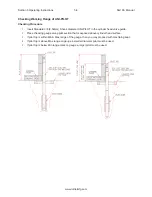
Setting The Rest Of The Heights
Raise the spindle with the rapid up or feed up button until the end of the pilot (using unipilot system) or
cutter head (std. system) clears and can float guide to guide without interference, press and hold the
“HEAD CLEARANCE HEIGHT “ set button until the figure changes. You will notice that this figure has
changed and is now the same as the vertical figure on left.
Next, lower spindle with feed down or handwheel until the tip of pilot (unipilot system) is just above the
top of valve guide. Or until the cutter head (std. system) is just above the pilot. Press and hold the “RAPID
TO PILOT HEIGHT” button until figure changes. Next, lower spindle until pilot is 1/2” into guide (unipilot
system) or tool holder is over pilot 1/2” (std. system) press and hold the “LOWER CUTTERHEAD OVER
PILOT” button until figure changes.
Next we need to set the “START CUTTING HEIGHT” This is where the spindle will start turning. This
height needs to be above the highest seat. Usually .020-.030 is safe. If you know seats are all equal you
can go lower but it is possible to crash machine if not careful here. I would suggest not going any closer
until you have good experience with the machine.
To set this tap on the figure next to the MOVE button. A keyboard will pop up, enter in your height (.030)
and press ENTER.
Last is to set the “FINISH CUTTING DEPTH” same thing here, tap the figure next to the MOVE button
and enter in your depth you want to cut (.-003 is a good starting point) you must also tap the +/- button
before you push ENTER. This will make the figure a negative number. This is how much below the preset
vertical zero the machine will cut the seat.
Retract height: Set where spindle retracts to after cutting is done by taping any of the “SET buttons. When
this is done the button will turn RED. This is where the spindle will retract to after cutting.
Set workhead float after auto cycle buy checking box.
Make sure the Head Clearance Height is sufficient for the Tool holder or pilot to clear
the Cylinder Head and the fixture when moving the work Head across.
The Vertical stops have now been set. These steps have to be done on every new cylinder head. This
information will be save on the Head Selection mode. Is importing to save changes every time you getting
out of each mode. The next time you pull up the mode all settings will be stored. All you have to do is set
your “vertical zero” and you are ready to go.
Seat Counter Boring Screen
This will be the same seat cutting except for the vertical zero position. This is set when the counter bore
cutter first comes into contact with the casting it will be cutting.
Summary of Contents for SG10A
Page 2: ......
Page 4: ......
Page 8: ...Section 1 Introduction SG10A Manual www rottlermfg com 1 4...
Page 22: ...Section 2 Installation SG10A Manual www rottlermfg com 2 13...
Page 61: ...Section 5 Operating Instructions SG10A Manual www rottlermfg com 5 15...
Page 62: ...Section 5 Operating Instructions SG10A Manual www rottlermfg com 5 16...
Page 82: ...Section 6 Maintenance SG10A Manual www rottlermfg com 6 9...
Page 90: ...Section 8 Machine Parts SG10A Manual www rottlermfg com 8 3 Base Table and Riser Assembly...
Page 91: ...Section 8 Machine Parts SG10A Manual www rottlermfg com 8 4...
Page 92: ...Section 8 Machine Parts SG10A Manual www rottlermfg com 8 5...
Page 93: ...Section 8 Machine Parts SG10A Manual www rottlermfg com 8 6 Base Assembly...
Page 94: ...Section 8 Machine Parts SG10A Manual www rottlermfg com 8 7...
Page 95: ...Section 8 Machine Parts SG10A Manual www rottlermfg com 8 8...
Page 96: ...Section 8 Machine Parts SG10A Manual www rottlermfg com 8 9 Spindle Assembly...
Page 97: ...Section 8 Machine Parts SG10A Manual www rottlermfg com 8 10...
Page 98: ...Section 8 Machine Parts SG10A Manual www rottlermfg com 8 11...
Page 99: ...Section 8 Machine Parts SG10A Manual www rottlermfg com 8 12...
Page 100: ...Section 8 Machine Parts SG10A Manual www rottlermfg com 8 13 Transmission Assembly...
Page 101: ...Section 8 Machine Parts SG10A Manual www rottlermfg com 8 14...
Page 102: ...Section 8 Machine Parts SG10A Manual www rottlermfg com 8 15...
Page 103: ...Section 8 Machine Parts SG10A Manual www rottlermfg com 8 16 Head Support Assembly...
Page 104: ...Section 8 Machine Parts SG10A Manual www rottlermfg com 8 17...
Page 105: ...Section 8 Machine Parts SG10A Manual www rottlermfg com 8 18...
Page 106: ...Section 8 Machine Parts SG10A Manual www rottlermfg com 8 19 Pneumatic Circuit Diagram...
Page 107: ...Section 8 Machine Parts SG10A Manual www rottlermfg com 8 20 Electrical Components...
Page 110: ...Section 9 Options SG10A Manual www rottlermfg com 9 2...
Page 112: ...Section 10 Material Data Safety Sheets SG10A Manual www rottlermfg com 10 2...
Page 113: ...Section 10 Material Data Safety Sheets SG10A Manual www rottlermfg com 10 3...
Page 114: ...Section 10 Material Data Safety Sheets SG10A Manual www rottlermfg com 10 4...
Page 115: ...Section 10 Material Data Safety Sheets SG10A Manual www rottlermfg com 10 5...
Page 116: ...Section 10 Material Data Safety Sheets SG10A Manual www rottlermfg com 10 6...
Page 117: ...Section 10 Material Data Safety Sheets SG10A Manual www rottlermfg com 10 7...
Page 118: ...Section 10 Material Data Safety Sheets SG10A Manual www rottlermfg com 10 8...
Page 119: ...Section 10 Material Data Safety Sheets SG10A Manual www rottlermfg com 10 9...
Page 120: ...Section 10 Material Data Safety Sheets SG10A Manual www rottlermfg com 10 10...
Page 121: ...Section 10 Material Data Safety Sheets SG10A Manual www rottlermfg com 10 11...
Page 122: ...Section 10 Material Data Safety Sheets SG10A Manual www rottlermfg com 10 12...
Page 123: ...Section 10 Material Data Safety Sheets SG10A Manual www rottlermfg com 10 13...
Page 124: ...Section 10 Material Data Safety Sheets SG10A Manual www rottlermfg com 10 14...


