Section 2 Installation
SG10A Manual
www.rottlermfg.com
2-8
Preparation for Placement
Air supply is connected at the left side of the machine, at base of lower casting. Connection can either
be a quick disconnect or permanent threaded connection. Be certain to use an adequately sized airline,
permitting proper operation of float. Air pressure should never drop below 90 PSI at any time. Failure to
provide adequate air supply may cause improper floating and clamping.
At this time, some customers will install a T fitting or manifold at the regulator, allowing another air hose to
be connected, providing a connection point for air tools. The auxiliary hose, if fitted, should be of sufficient
length to easily reach the entire front of the machine.
This machine comes pre-wired and ready to be connected to the power source. The power source should
meet all local and national electrical codes. This service should connect to its own circuit breaker or fuse.
The machine will require 220 VAC, 15 amp, single-phase power supply.
Machine Installation
• Lift Machine using a fork lift. Move fork lift to front of Machine and separate forks so they are visually
centered.
• Insert forks under front-center of Machine, using care not to damage Foot Pedals Valve or Air Lines.
Tilt forks slightly upward so Machine will lean toward fork lift and lift Machine.
• While Machine is on fork lift, install six (6) Leveling Screws and Jam Nuts in holes provided in bottom
of Machine Base. Two (2) Screws installed in rear-corners and two (2) Screw installed in front corners
of Machine Base will serve as Leveling Screws; while two (2) Screws installed in center of Machine
Base will serve only as Support Screws.
• Move Machine to desired location and placed leveling bolts over the center hole of the Leveling Pad.
Be certain to allow sufficient clearance to allow access for leveling and also for connecting air and
electrical lines.
• Lower machine onto leveling pads making certain that the leveling bolts align into counter bore on
leveling pads.
•
Be certain nothing interferes with air or electrical tracking running from the floating head assembly to
the cabinet.
• Determine there is no possibility of air or electrical tracking dragging on wall surfaces or adjacent
machinery.
• Wipe top Rails with a clean, dry cloth to remove protective shipping oil.
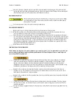
Do not attempt to move the Work Head unless Air Supply is connected, and air
valve is turned on and power has been turn on (make sure the EMERGENCY STOP
Button is off). From the touch screen, float the workhead, spray, and clean surface with (WD40) or similar
degreaser and flow the work Head side by side to remove all the shipping oil from under the work head.
(Top Upper surfaces rails should be clean and free of oil).
Summary of Contents for SG10A
Page 2: ......
Page 4: ......
Page 8: ...Section 1 Introduction SG10A Manual www rottlermfg com 1 4...
Page 22: ...Section 2 Installation SG10A Manual www rottlermfg com 2 13...
Page 61: ...Section 5 Operating Instructions SG10A Manual www rottlermfg com 5 15...
Page 62: ...Section 5 Operating Instructions SG10A Manual www rottlermfg com 5 16...
Page 82: ...Section 6 Maintenance SG10A Manual www rottlermfg com 6 9...
Page 90: ...Section 8 Machine Parts SG10A Manual www rottlermfg com 8 3 Base Table and Riser Assembly...
Page 91: ...Section 8 Machine Parts SG10A Manual www rottlermfg com 8 4...
Page 92: ...Section 8 Machine Parts SG10A Manual www rottlermfg com 8 5...
Page 93: ...Section 8 Machine Parts SG10A Manual www rottlermfg com 8 6 Base Assembly...
Page 94: ...Section 8 Machine Parts SG10A Manual www rottlermfg com 8 7...
Page 95: ...Section 8 Machine Parts SG10A Manual www rottlermfg com 8 8...
Page 96: ...Section 8 Machine Parts SG10A Manual www rottlermfg com 8 9 Spindle Assembly...
Page 97: ...Section 8 Machine Parts SG10A Manual www rottlermfg com 8 10...
Page 98: ...Section 8 Machine Parts SG10A Manual www rottlermfg com 8 11...
Page 99: ...Section 8 Machine Parts SG10A Manual www rottlermfg com 8 12...
Page 100: ...Section 8 Machine Parts SG10A Manual www rottlermfg com 8 13 Transmission Assembly...
Page 101: ...Section 8 Machine Parts SG10A Manual www rottlermfg com 8 14...
Page 102: ...Section 8 Machine Parts SG10A Manual www rottlermfg com 8 15...
Page 103: ...Section 8 Machine Parts SG10A Manual www rottlermfg com 8 16 Head Support Assembly...
Page 104: ...Section 8 Machine Parts SG10A Manual www rottlermfg com 8 17...
Page 105: ...Section 8 Machine Parts SG10A Manual www rottlermfg com 8 18...
Page 106: ...Section 8 Machine Parts SG10A Manual www rottlermfg com 8 19 Pneumatic Circuit Diagram...
Page 107: ...Section 8 Machine Parts SG10A Manual www rottlermfg com 8 20 Electrical Components...
Page 110: ...Section 9 Options SG10A Manual www rottlermfg com 9 2...
Page 112: ...Section 10 Material Data Safety Sheets SG10A Manual www rottlermfg com 10 2...
Page 113: ...Section 10 Material Data Safety Sheets SG10A Manual www rottlermfg com 10 3...
Page 114: ...Section 10 Material Data Safety Sheets SG10A Manual www rottlermfg com 10 4...
Page 115: ...Section 10 Material Data Safety Sheets SG10A Manual www rottlermfg com 10 5...
Page 116: ...Section 10 Material Data Safety Sheets SG10A Manual www rottlermfg com 10 6...
Page 117: ...Section 10 Material Data Safety Sheets SG10A Manual www rottlermfg com 10 7...
Page 118: ...Section 10 Material Data Safety Sheets SG10A Manual www rottlermfg com 10 8...
Page 119: ...Section 10 Material Data Safety Sheets SG10A Manual www rottlermfg com 10 9...
Page 120: ...Section 10 Material Data Safety Sheets SG10A Manual www rottlermfg com 10 10...
Page 121: ...Section 10 Material Data Safety Sheets SG10A Manual www rottlermfg com 10 11...
Page 122: ...Section 10 Material Data Safety Sheets SG10A Manual www rottlermfg com 10 12...
Page 123: ...Section 10 Material Data Safety Sheets SG10A Manual www rottlermfg com 10 13...
Page 124: ...Section 10 Material Data Safety Sheets SG10A Manual www rottlermfg com 10 14...

