1
USER'S MANUAL
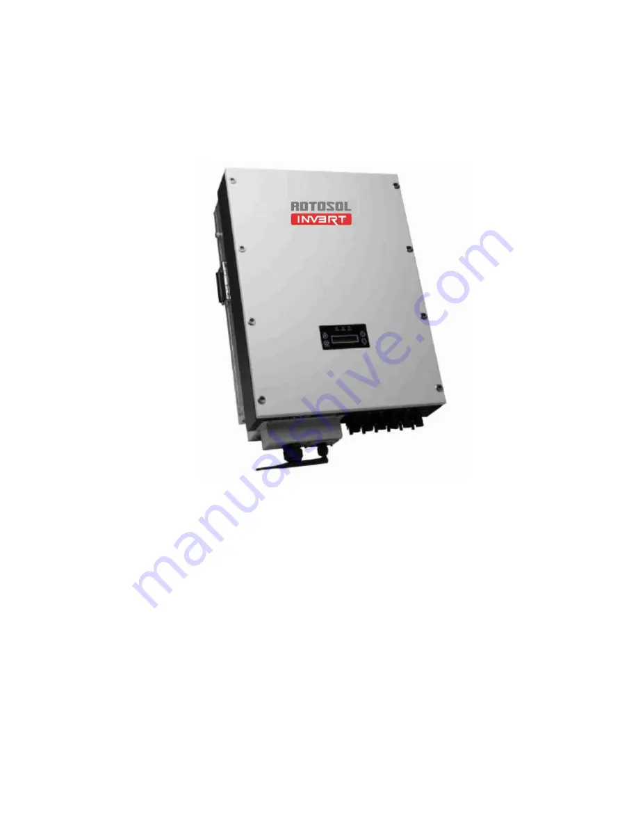
On-Grid PV Inverter
Series: RITxK(x=5,6,8,10,15,20,30,40,50,60)
USERS MANUAL
Page 1: ...1 USER S MANUAL On Grid PV Inverter Series RITxK x 5 6 8 10 15 20 30 40 50 60 USERS MANUAL...
Page 2: ...ntly increasing demands for global energy The newly designed PV Inverter features itself with full load high efficiency high reliability and user friendly interface The maximum conversion efficiency o...
Page 3: ...connection areas on the bottom of theInverter 13 5 2 Connection to the Public Grid AC 13 5 3 Connection to the PV Generator DC 16 6 System Diagram 21 7 Operation 23 7 1 Overview of Control and Displa...
Page 4: ...Systems Power Plants 5 60KW RIT5K RIT6K RIT8K RIT10K RIT15K RIT20K RIT30K RIT40K RIT50K RIT60K Please keep this manual all time available in case of emergency 1 2 Target Group This manual is for quali...
Page 5: ...sure of Inverter can become hot during operation To reduce the risk of injury do not touch the cover heat sink at the back of the PV lnverter or nearby surfaces while Inverter is operating 6 Do not us...
Page 6: ...6 2 2 Explanations of Symbols...
Page 7: ...t Quantity Description Object Quantity Description A 1 Solar inverter B 1 Wall mounting bracket C 1 User manual D 1 Certificate of inspection E 1 Installation diagram F 1 Notice for installation G 1 W...
Page 8: ...ntify the inverter by the type label Information such as serial number Serial No and model name of the inverter as well as the device s technical parameters are specified on the type label The type la...
Page 9: ...propriate Mounting Location Consider the following points when selecting where to install The mounting method and location must be suitable for the inverter s weight and dimensions The inverter must b...
Page 10: ...und the inverter for better ventilation Vertical installation wiring area must be downside lateral installation is not allowed in backward tilted installation tilt angle should not exceed 30 degrees F...
Page 11: ...n and drill the holes for the screws 2 Fix the wall mounting bracket with the equipped self tapping screw 3 Hang the inverter to the mounting bracket and ensure the slot is fitted on the bracket 4 Che...
Page 12: ...of DC input conductor lead should be 4mm2 PV wire that of AC output conductor should also be 4mm2 cooper wire and that of external ground conductor should be 4mm2 cooper wire 5 On both sides of invert...
Page 13: ...onnecting the PV strings b DC connectors for connecting the PV strings c WiFi RS485 Communication Waterproof Connector d Waterproof Junction Box AC connection e DC Switch 5 2 Connection to the Public...
Page 14: ...connect the circuit breaker between the inverter and the grid 1 Disconnect the DC and AC breaker DC switch in the OFF state 2 Disconnect the DC and AC breaker DC switch in the OFF state 3 Assembly yel...
Page 15: ...14 0 5mm Connect the cable with terminals 5 Run the cable harness with the pressed terminals through the junction box and insert the black cable harness L1 L2 and L3 into the caps of N W V and U as s...
Page 16: ...Disconnect circuit breakers and switches on bothAC and DC sides 5 3 1 Conditions for the DC Connection The connected PV modules must meet following requirements Same type Same model Identical alignmen...
Page 17: ...ct to the inverter all connection cables of the PV modules must be equipped with the DC plug connectors provided You will find the necessary DC plug connector for DC connection in the package To assem...
Page 18: ...arrays Stripping length is 12 15mm sectional area is 4 mm2 as below Insert the DC wire to metal connecting tube Make sure all line heads are in the connecting tube as picture blow Use crimping pliers...
Page 19: ...o life due to high voltage in the inverter Before connecting the PV generator ensure that the AC DC circuit breaker is switched off Notes 1 Make sure that you have disconnected circuit breakers and sw...
Page 20: ...and DC B of connecting sockets for DC input and each group contains two pairs of connecting sockets DC and DC Make sure at least one pair of DC terminal in each group is connected with PV array in in...
Page 21: ...e Inverter is grid connected it controls the current amplitude according to the PV Panel power supply Inverter always tries to convert the maximum power from the PV array 3 QF1 QF2 Breaker The current...
Page 22: ...n protection voltage 2 5KV DC side nominal discharge current 20KA second grade lightning protection protection voltage 3 2KV 6 The wiring distance between the inverter and the distribution box should...
Page 23: ...verview of Control and Displays There are four function keys on the front panel UP DOWN ESC ENT The keypad is used for Up and Down keys Scrolling the displayed parameter or modify the adjustable param...
Page 24: ...thePOWERLEDturnson Whentheinverterisoperatingandfeedelectricityintotheutilitygrid normally theCOMLEDturnson WhenthereisfaultyinthePVSystemorinverter theFAULTLEDflashes andthefaulty code willbeshownon...
Page 25: ...The inverter will delay 1 second and automatically jump to the System Checking Interface 7 4 1 First Boot Setting First turned on power the inverter will delay 1 second and automatically jump to the...
Page 26: ...verter starts up next time Operation status and generation information of inverter will be show on the main interface Display Info the current time will be shown in the last line Generation informatio...
Page 27: ...ridpowerCtrl Press UP and DOWN to select the query item press Ent to get in and Esc back to main interface System Info System Information shows country standard and operation parameters UPand DOWN cou...
Page 28: ...contact after sales if the problem still exists Error Record Shows Display Description Nub Total Fault sequence Total faults number E Fault Code ST Fault starting time ET Fault Ending Time SET Reset t...
Page 29: ...ss setting interface press UPand DOWN to change values Press ENT to confirm SN It shows inverter s serial Number SetPowerCtrl This item is for setting grid connecting power limitation Press ENT to ent...
Page 30: ...y out of range 2 Please contact with local dealer if error remains the same after several reset Machine failure GridV OutLim 1 Off Phase 1 Disconnect the input output switch check the AC side wiring a...
Page 31: ...K 1 Electricity grid abnormal 1 After electricity grid returns to normal the machine will automatically restart 2 Bus differential fault 2 Please contact with local dealer if error remains the same af...
Page 32: ...Bus voltage protection Please contact with local dealer if error remains the same after several reset IntProtectl High Bus voltage protection Please contact with local dealer if error remains the same...
Page 33: ...abnormal protection Please contact with local dealer if error remains the same after several reset IsolationErr 1 PV or PV earthing 2 Lightening 3 Machine failure 1 Check PV and PV ground impedance m...
Page 34: ...k both AC and DC wiring If the input DC voltage is higher than start up voltage the inverter still doesn t work please call local service If it is intended to replace the cable or open the enclosure l...
Page 35: ...have the leakage current 9 5 Monitoring Fault 9 5 1 cannot search wifi single of inverter before open the cover of monitoring card please make sure the inverter is generation a check the cable wiring...
Page 36: ...ountry code is correct b check all of the AC wiring point is well connected c measure the AC frequency is within normal range d re setting the AC frequency range 49 0 51 0Hz 9 6 6 Other Fault Report 9...
Page 37: ...ase notice the and The normal value is 0 33 0 37V with with And specific value could compare with normal inverter Value close to the zero or bigger than normal range stands the diode is damaged For th...
Page 38: ...38...
Page 39: ...normal value is 0 3 0 4V Value close to the zero stands the component is damaged b the normal resistance between Pin 2 and Pin 3 should be infinity value close to the zero stands the component is dama...
Page 40: ...Power Diode Position Number 5th Generation Single MPPT D1 5th Generation Dual MPPT D9 D13 D30 D31 IGBT MOSFET Position Number 5th Generation Single MPPT Q2 QA1 QA2 QA3 QB1 QB2 QB3 5th Generation Dual...
Page 41: ...r voltage is 5Vdc If the voltage abnormal it stands the power PCB is damaged 9 9 Inverter Frequently Tripping Due to Grid Fluctuation 9 9 1 Check the grid voltage with multimeter if voltage range goes...
Page 42: ...9 9 4 Press enter key to set the voltge range and enter the password as shown in Fig 5 Fig 5 9 9 5 Adjust the voltage range of Vac Min and Vac Max by up down key and set it at Vac Max 450V and Vac Min...
Page 43: ...and controls pvt ltd www rotosol solar ADD 2102 3 4 Vitthal Udhyognagar Near Anand Gujarat 388121 India Phone 91 9227110023 24 25 E MAIL invert rotosol solar Website www rotosol solar Annex Warranty T...
Page 44: ...uction or installation works Solar panels input parameters exceed the inverter s allowed range Product malfunction or damage due to installation on movable device or in vibration occasions Failure or...
Page 45: ...it www rotosol solar for dealer installer s contact details Of course customers may also contact Rotosol f they need help or advice 5 Force Majeure Force majeure is not artificially unavoidable and in...
Page 46: ...Rotomag motors and controls pvt ltd www rotosol solar ADD 2102 3 4 Vitthal Udhyognagar Near Anand Gujarat 388121 India Phone 91 9227110023 24 25 Customer Care Number 1800 123 4412 E MAIL invert rotos...