


BRP-Rotax
INSTALLATION MANUAL
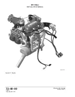
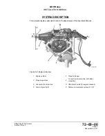
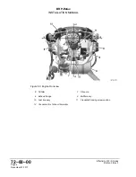
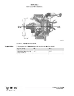
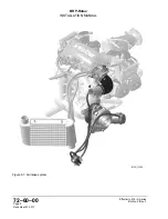
SYSTEM DESCRIPTION
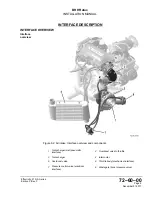
For a detailed System description refer to the latest issue of the Operators Manual.
SYSTEM LIMITATIONS
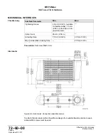
Air intake
Following requirements may be used:
System Limit
Min.
Max.
Flow rate
400 kg/h
Pressure loss (between ambi-
ent pressure and compressor
inlet at 16000 ft)
10 mbar
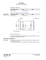
Icing in the area of the air intake needs to be avoided. The prevention of icing lies within
the aircraft manufacturer’s responsibility.
Airbox reference
pressure
The reference pressure of the fuel system is the airbox pressure.
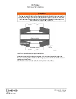
Air intake ducting
The air intake ducting must not be changed in any case (connection between Intercooler
and overboost valve, between Turbocharger and Intercooler, between Overboost valve
and throttle).
System Limit
Min.
Max.
Intake pressure loss (Engine
Speed: 5500 ±50 rpm;
Airflow: 360-366 kg/min)
85 mbar
Intake pressure loss (Engine
Speed: 5800 ±50 rpm;
Airflow: 384-396 kg/min)
90 mbar
PCV ducting
All pneumatic connections leading from and to the Pressure Control Valve (PCV) may not
be changed. Changes in length and diameter of the connections will have an significant ef-
fect on the wastegate control. Depending on the installation heat protection must be
foreseen.
System Limit
Min.
Max.
Bending radius on tube
centerline
60 mm
Valid installation
positions
The intercooler as well as the PCV must be installed vibration-decoupled from the engine.
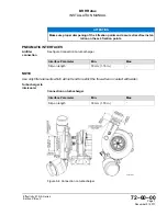
Compressor
housing
Compression housing must not be rotated. The wastegate functionality can be affected.
Throttle lever
Adjust Bowden cable such that throttle valve can be fully opened and closed. Use Bowden
cable with minimized friction so that the return spring on the throttle valve can open the
throttle valve completely.
Effectivity: 915 i A Series
Edition 0/Rev. 0
Page 3
December 01 2017
Summary of Contents for 915 iS 3 A
Page 165: ......