BRP-Rotax
INSTALLATION MANUAL
WARNING LAMPS
Warning Lamp A,
B (-H1, -H2)
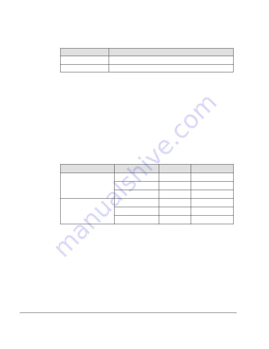
Interface Parameter
Value
Nominal voltage
12
Nominal current
max. 120 mA
Instead of common lamps also LED lamps (-H1 V2, -H2 V2) can be used. In this case a
appropriate pre-resistor must be conducted serial to the LED. An additional resistor paral-
lel to the LED avoids that the ECU detects an open circuit at this warning lamp.
CAN INTERFACES
Display CAN
Two independent Display CAN interfaces are provided for displaying or recording engine
data. When displaying engine data, it must be ensured that data of both CAN interfaces is
used, providing truly redundant data indication or data indication of suitable reliability, con-
sistent with the safety objective of the final application. The proof of consistency with the
safety objective of the final application is the responsibility of the installer.
Maintenance CAN
To be able to connect the Maintenance CAN A and B with the B.U.D.S Aircraft USB-to-
CAN converter the Maintenance CAN A and B should be connected with two separate
Sub-D DE9 (9-pin) sockets. It is highly recommended to conduct those connectors due to
the fact that the B.U.D.S. Aircraft is a central element when it comes to diagnosis and
maintenance of this engine.
CAN Type
Description
HIC Pin
Sub-D DE9 Pin
Maintenance CAN A
CAN_LOW_2_A
11 (HIC A)
2
CAN_GND_2_A
10 (HIC A)
3
CAN_HIGH_2_A
12 (HIC A)
7
Maintenance CAN B
CAN_LOW_2_B
15 (HIC B)
2
CAN_GND_2_B
14 (HIC B)
3
CAN_HIGH_2_B
16 (HIC B)
7
It is recommended not to connect maintenance and diagnostic interfaces LANE A and
LANE B together.
Page 10
December 01 2017
Effectivity: 915 i A Series
Edition 0/Rev. 0
Summary of Contents for 915 iS 3 A
Page 165: ......


