background image

88

12.  Electrical:

  Have a certified electrician run 

appropriate power supply to motor, Fig. 21 & 22. Size 

wire for 20 amp circuit.  See Motor Operating Data Table.

CAUTION

 Never operate the motor on line voltage less 

than 208V.  Motor damage may occur.

IMPORTANT:

  Use separate circuit for each power unit.  

Protect each circuit with time delay fuse or circuit breaker.  

For single phase 208-230V, use 20 amp fuse.  Three phase 

208-240V, use 20 amp fuse.  For three phase 400V and 

above, use 10 amp fuse.  For wiring see Fig. 21 & Fig. 22.  

All wiring must comply with NEC and all local electrical 

codes.

Note:

 60Hz. single phase motor 

CAN NOT

 be run on 

50Hz. line without a physical change in the motor.

13.  Overhead switch:

  Check overhead switch assembly 

to assure that switch bar is depressing switch plunger 

sufficiently to actuate the switch.  The overhead switch 

is wired normally open, see Fig. 15a, Fig. 16a, and Fig. 

16b.  Lift will not operate until weight of switch bar is 

depressing  switch plunger.  Verify that Power Unit stops 

working when switch bar is raised, and re-starts when the 

bar is released.

CAUTION

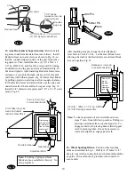
  When bleeding, hold a shop cloth over 

bleeder screw to buffer the air and fluid while bleeder 
valve is open.

14.  Oil Filling & Bleeding:

  Use Dexron III ATF, or 

Hydraulic Fluid that meets ISO 32 specifications.  Remove 

fill-breather cap, Fig. 15b.  Pour in (8) quarts of fluid.  

Start unit, raise lift about 2 ft.  Open cylinder bleeders 

approx. 2 turns, Fig. 9.  

Close bleeders when fluid streams.  Fully lower lift.  Add 

more fluid until it reaches fill line on the tank.  System 

capacity is (14) quarts.  Replace fill-breather cap.


CAUTION

  If fill-breather cap is lost or broken, order 

replacement.  Reservoir must be vented.

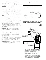
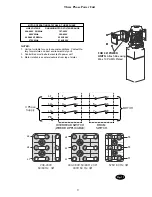
Single Phase Power Unit

MOTOR OPERATING DATA TABLE - SINGLE PHASE


LINE VOLTAGE 

RUNNING MOTOR VOLTAGE RANGE 


208-230V  50Hz. 

197-253V 


208-230V  60Hz. 

197-253V 

Note: 60Hz. Single phase motor CAN NOT be run on 

50Hz. line without a physical change in the motor.

Overhead Switch 
Max. Voltage: 277V
Max. Current: 25A

Connect supply to wires in box as 
per Fig. 22.  Attach ground wire to 
screws provided.

Fill Breather Cap

Attach ground wire here.

208-230V 60Hz 
Single Phase

Attach black wire
to black wire.

Attach white
wire to red wire.

Black

Green

White

M

230V

60Hz

1 Ø

Black

Green

White

Overhead

Limit Switch

Up

Switch

White

Black

Black

NOTE:

 Assure cord used for connection

between the overhead switch and power
unit is of the type specified in:

UL201, Sections 10.1.1.3 & 10.1.1.4 

(Example:  SO, G, STO) Size for 25 amp
circuit.  See UL 201, Section 15 for proper
wiring requirements for this connection. 

Fig. 15b

Summary of Contents for Sprinter SPO15

Page 1: ...ft All rights reserved IN20379 CO6363 1 Rev A 11 22 2005 I N S T A L L A T I O N I N S T R U C T I O N S SPO15 SPO18 Sprinter SPO15 3A0 Lifts Capacity 11 000 lbs Standard SPO15 300 Series Lifts Capaci...

Page 2: ...n using the standard supplied 3 4 x 5 1 2 lg anchors if the top of the anchor exceeds 2 1 4 above the oor grade you DO NOT have enough embedment Fig 1 Drill 18 3 4 dia holes in concrete oor using hole...

Page 3: ...IEW FROM APPROACH SIDE All Star Washers are to be mounted on the Right side column to ensure grounding of overhead limit switch Star Washers are not needed when mounting to Left Side column Notice the...

Page 4: ...power unit bracket using Push Nuts to hold in place Fig 8a Mount unit with motor up to column bracket and install 4 5 16 star washers and 5 16 Nuts Install and hand tighten Branch Tee to pump until O...

Page 5: ...easier to tie off lower studs rst A Run cable stud up through the lower tie off plate and or bracket s and or spacer s depending on the lift model Fig 11 B Push cable up until stud is above top of car...

Page 6: ...1 spacer provided For 15 height carriages use pattern four with 472 cable Has 1 spacer provided For 16 6 height with 472 long cable or for 14 6 height with 424 long cable both use pattern one 4 3 1 2...

Page 7: ...e Install air line from lowering valve to union tee then to the right column air cylinder K Install air line from union tee to left column air cylin der Fig 14 L Mount lowering valve and bracket to co...

Page 8: ...er valve is open 14 Oil Filling Bleeding Use Dexron III ATF or Hydraulic Fluid that meets ISO 32 speci cations Remove ll breather cap Fig 15b Pour in 8 quarts of uid Start unit raise lift about 2 ft O...

Page 9: ...TABLE THREE PHASE LINE VOLTAGE RUNNING MOTOR VOLTAGE RANGE 208 240V 50 60Hz 197 253V 400V 50Hz 360 440V 440 480V 50 60Hz 396V 528V 575V 60Hz 518V 632V FOR 3 POWER UNITS Attach Box using M5 x 10 PHMS...

Page 10: ...in Fig 18 so that the rounded edge top side of the gear teeth is fac ing upward Then install the three 3 3 8 16NC x 1 1 2 Lg HHCS 12 total for all 4 arms and 3 8 Spring Lockwashers into the gear and a...

Page 11: ...l if required Repeat air bleeding of cylinders 19 Final Adjustments Raise lift to check equalizer cable tension Below carriage grasp adjacent cables between thumb and fore nger with about 15 lbs effor...

Page 12: ...erved Unless otherwise indicated ROTARY DOVER and all other trademarks are property of Dover Corporation and its affiliates Rotary World Headquarters 2700 Lanier Drive Madison IN 47250 USA www rotaryl...

Reviews: