background image

Voyager Maintenance Guide (v02)

Hard Drive Maintenance • 4–1

Hard Drive Maintenance

Voyager utilizes a software-based RAID system in conjunction with an ICH10 chipset on the system motherboard. 
This setup relies on the Windows operating system and host processor to perform all of the RAID functionality.

MegaRAID Storage Manager

The MegaRAID Storage Manager is used to manage, maintain, and monitor the Voyager server RAID array.

Use the following procedure to open the MegaRAID Storage Manager.

To open the MegaRAID Storage Manager:

1.

Log in to the Voyager server using the following (no password):

Username

 — 

Voyager


Password

 — 

beyondinfinity


2.

In the Windows start menu, click 

MegaRAID Storage Manager

 > 

StartupUI

.

The 

MegaRAID Storage Manager


Server Details

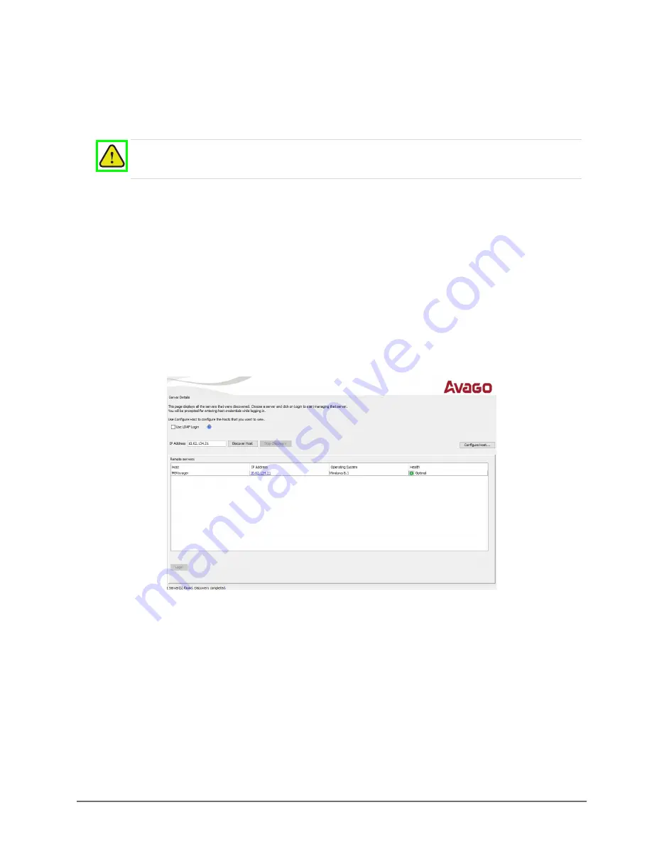
 window opens.

Figure 4.1  

Storage Manager - Server Details

Warning

 — Always use proper Windows shutdown procedure. NEVER HARD POWER OFF THE 

UNIT. Hard shutdown may cause failures in the RAID, taking one or more drives offline.

Summary of Contents for YOYAGER X1

Page 1: ...Voyager X1 Maintenance Guide Version 02 ...

Page 2: ...people that make things happen At Ross our employees are a special group Our employees truly care about doing a great job and delivering a high quality customer experience every day This code of ethics hangs on the wall of all Ross Video locations to guide our behavior 1 We will always act in our customers best interest 2 We will do our best to understand our customers requirements 3 We will not s...

Page 3: ...ritten permission of Ross Video While every precaution has been taken in the preparation of this document Ross Video assumes no responsibility for errors or omissions Neither is any liability assumed for damages resulting from the use of the information contained herein Patents Patent numbers US 7 034 886 US 7 508 455 US 7 602 446 US 7 802 802 B2 US 7 834 886 US 7 914 332 US 8 307 284 US 8 407 374...

Page 4: ...f damage or injury to persons or equipment Warning The symbol with the word Warning within the equipment manual indicates a potentially hazardous situation which if not avoided could result in death or serious injury Caution The symbol with the word Caution within the equipment manual indicates a potentially hazardous situation which if not avoided may result in minor or moderate injury It may als...

Page 5: ... in this product The power supply outputs are considered an Energy Hazard 240VA To avoid the risk of contact with the Energy Hazard and to completely de energize the apparatus remove all power supply cords from the product s AC appliance inlet s prior to servicing Warning 9 Indoor Use To reduce the risk of fire or electric shock do not expose this apparatus to rain or moisture Warning 10 This prod...

Page 6: ...oHS The Environmentally Friendly Use Period EFUP and Hazardous Substance Tables have been established for all products The Hazardous substances tables are available on our website at http www rossvideo com about ross company profile green practices china rohs html 电器电子产品中有害物质的使用 Ross Video Limited 按照以下的标准对所有组件和流程进行了审查 电器电子产品有害物质限制使用管理办法 也被称为中国 RoHS 所有产品都具有 环保使用期限 EFUP 和有害物质表 目前 我们正在更新我们所有的产品手册 有害物...

Page 7: ...expense CANADA This Class A digital apparatus complies with Canadian ICES 003 Cet appareil numerique de la classe A est conforme a la norme NMB 003 du Canada EUROPE This equipment is in compliance with the essential requirements and other relevant provisions of CE Directive 93 68 EEC AUSTRALIA This equipment has been tested to AS NZS CISPR32 2015 AMD1 2020 and found to comply with the limits for a...

Page 8: ... while defective items undergo repair Return packing shipping and special handling costs are the responsibility of the customer This warranty is void if products are subjected to misuse neglect accident improper installation or application or unauthorized modification In no event shall Ross Video Limited be liable for direct indirect special incidental or consequential damages including loss of pr...

Page 9: ...ural resources Ross Video encourages you to use the appropriate take back systems These systems will reuse or recycle most of the materials from your end of life equipment in an environmentally friendly and health conscious manner The crossed out wheeled bin symbol invites you to use these systems If you need more information on the collection reuse and recycling systems please contact your local ...

Page 10: ...ss Office Fax 1 613 652 4886 1 613 652 4425 Toll Free Technical Support 1 844 652 0645 North America 800 1005 0100 International Alternately you can contact Technical Support 1 613 652 4886 After Hours Emergency 1 613 349 0006 E mail for Technical Support techsupport rossvideo com E mail for General Information solutions rossvideo com Website http www rossvideo com ...

Page 11: ...3 9 Attaching the Cables 3 10 Powering Up the System 3 11 Powering Down the System 3 11 Hard Drive Maintenance 4 MegaRAID Storage Manager 4 1 RAID Array Consistency Check 4 3 RAID Array Drive Replacement 4 4 Hardware Maintenance 5 Replacing a System Drive 5 1 Removing a System Drive 5 1 Replacing a System Drive 5 3 Removing and Re Installing the Top Panel 5 6 Replacing Cooling Fans 5 9 Replacing t...

Page 12: ...aintenance Guide v02 Appendix B Matrox 12G I O Cables B Matrox 12G Video Input Output Cables B 1 DSX LE5 12G Model B 1 Appendix C AJA Corvid 88 I O Cables C Features C 1 BNC Connections C 1 BNC Connection Pinout C 2 ...

Page 13: ...ers listed in the section Contacting Technical Support Our technical staff are always available for consultation training or service Documentation Conventions Special text formats are used in this guide to identify parts of the user interface text that a user must type or a sequence of menus and submenus that must be followed to reach a particular command Bold text Bold text is used to identify a ...

Page 14: ...business hours eastern time technical support personnel are available by telephone any time After hours and on weekends a direct emergency technical support phone line is available If the technical support person who is on call does not answer this line immediately a voice message can be left and the call will be returned shortly This team of highly trained staff is available to react to any probl...

Page 15: ...iew of Voyager System 1 Power LED Area This area includes the Voyager system Power button and LEDs for system components Refer to the section Power LED Area on page 3 2 for further information 2 USB Ports These ports can be used to transfer media to and from USB drives 3 HDD USB Ports These ports are inactive 4 HDD Alarm LED Area This area includes the alarm LEDs for the HDD hardware Refer to the ...

Page 16: ...tem Descriptions of individual components are contained in the legend below the diagram Figure 3 2 Power LED Area 1 Power Button Press this button to begin the boot procedure Press and hold the button for five seconds to power down the system after a hardware or software failure 2 Reset Button Press this button to reset the system after a hardware or software failure Pressing this button also rebo...

Page 17: ...ger system Descriptions of individual components are contained in the legend below the diagram Figure 3 3 HDD Alarm LED Area 1 Alarm Mute Button The alarm mute button is not active 2 Temperature Alarm LED This LED activates when the temperature inside the HDD hardware rises above the recommended operating temperature This LED is accompanied by an audible alarm 3 Fan Failure Alarm LED This LED acti...

Page 18: ...sed DIV D or DVI I 2 HDMI Port One HDMI port b provides output for a computer monitor 3 USB C Port One USB C port c provides output for a computer monitor 4 nVidia Quadro Sync II Two Frame Lock connections for synchronizing multiple displays Connect using CAT 6 UTP Ethernet cables 5 Matrox Video Input Output Cables Provide SDI video input and output as well as an analog reference point Refer to Ap...

Page 19: ...Ports Three Display Ports provide output for computer monitors Ensure the correct display port to DVI adapters are used DIV D or DVI I 2 USB C Port One USB C port provides output for a computer monitor 3 nVidia Quadro Sync II Two Frame Lock connections for synchronizing multiple displays Connect using CAT 6 UTP Ethernet cables 4 SFP Cage 1 Two connections for a small form factor pluggable SFP for ...

Page 20: ... display port to DVI adapters are used DIV D or DVI I 2 HDMI Port One HDMI port provides output for a computer monitor 3 USB C Port One USB C port provides output for a computer monitor 4 nVidia Quadro Sync II Two Frame Lock connections for synchronizing multiple displays Connect using CAT 6 UTP Ethernet cables 5 SDI HD BNC Provides 12G SDI video output Tx Refer to Appendix B Matrox 12G I O Cables...

Page 21: ...be used to transfer media to and from USB drives The port supports a maximum of 5 Gbit s Use of USB 3 1 certified cable and devices are required for USB 3 1 super speed data rates 3 Ethernet Ports Use one of these ports to connect the Voyager system to an internal network These ports can be used for high speed file transfer between the Voyager system and other computers on the internal network 4 U...

Page 22: ...ule can be hot swapped at a time Each power supply module can be attached to a separate power circuit to provide redundancy in case of power failure The diagram Figure 3 8 displays the parts of the power supply modules for the Voyager system A description of the A C Power Cord Connection is contained in the legend below the diagram Figure 3 8 Voyager System Power Supply Unit 1 A C Power Cord Conne...

Page 23: ...protection and supply wiring Appropriate consideration of equipment nameplate rating should be used when addressing this concern Reliable Earthing Reliable earthing of rack and desktop tower mounted equipment should be maintained Particular attention should be given to supply connections other than direct connections to the branch circuit e g use of power strips Installing the System in an Equipme...

Page 24: ...ts Voyager systems can run standalone or accept a network connection if required to connect to a production network Voyager systems also use this TCP IP network connection to support the Smart GPI Feature 6 Connect the GenLock signal cable to the REF IN BNC connector This connection is required to lock the Voyager system to the video timing of the facility The Voyager system supports the following...

Page 25: ...s on page C 1 For the Voyager 12G system connect the HD BNC video I O cables to their required destination see the Voyager User Guide or Help file for information about configuring the Key and Fill for the HD BNC connectors For the Voyager IP system insert pluggable SFP connectors into the SFP cages and attach the networking cables to the connectors Voyager systems provide SD HD SDI outputs If you...

Page 26: ...n and monitor the Voyager server RAID array Use the following procedure to open the MegaRAID Storage Manager To open the MegaRAID Storage Manager 1 Log in to the Voyager server using the following no password Username Voyager Password beyondinfinity 2 In the Windows start menu click MegaRAID Storage Manager StartupUI The MegaRAID Storage Manager Server Details window opens Figure 4 1 Storage Manag...

Page 27: ... labelled Voyager The Enter User Name Password dialog box opens Figure 4 2 Storage Manager Login 4 Enter the following Username Voyager Password beyondinfinity 5 From the Login Mode list select Full Access 6 Click Login The MegaRAID Storage Manager opens Figure 4 3 Storage Manager Dashboard Tab ...

Page 28: ...when Voyager is not in use To run a consistency check on the Voyager RAID array 1 Open the MegaRAID Storage Manager 2 In the MegaRAID Storage Manager from the menu bar select Manage Check Consistency The Group Consistency Check dialog box opens Figure 4 4 Storage Manager Group Consistency Check 3 From the Select Virtual Disks section select the check boxes of the virtual drives to check for consis...

Page 29: ...igured drive is inserted to repair the failed virtual drive the new drive is highlighted by a red LED icon displayed to the right of the drive icon Rebuilding a drive consumes bandwidth on the Voyager server and is ideally done during off hours or when the server has a low workload To prevent accidental data loss back up all data before replacing a drive in the Voyager RAID array Depending on the ...

Page 30: ...the Logical tab The drives contained in the Voyager RAID array are listed in the Logical tab Figure 4 6 Storage Manager Logical Tab Unconfigured drives are highlighted by a red LED icon displayed to the right of the drive icon Figure 4 7 Storage Manager Drive Offline ...

Page 31: ...edia and System Drives For instructions on removing and replacing drives refer to the sections Removing a System Drive on page 5 1 and Replacing a System Drive on page 5 3 5 Once the new drive is in place in the Physical tab under Unconfigured Drives right click the new drive and select Change to Unconfigured Good 6 Right click the drive again and select Replace Missing Drive Figure 4 9 Storage Ma...

Page 32: ...rive again and select Make Drive Online A confirmation dialog opens Figure 4 11 Confirmation Dialog Putting Drive Online 9 Select the Confirm check box and then click Yes To view the build progress 1 Select Manage Show Progress to monitor the rebuild progess The Group Show Progress window opens Figure 4 12 Group Show Progress 2 Click Close when the process is complete ...

Page 33: ...of the Voyager system Caution Danger of Explosion if the system lithium battery is incorrectly replaced Replace only with the same or equivalent type of battery recommended by the manufacturer Dispose of used batteries according to the manufacturer s instructions by a qualified service person Protective Earth Static discharge can cause serious damage to sensitive devices Avoid handling any hard dr...

Page 34: ...e drive sled push the blue release button up to release the black handle The drive sled is released from the drive bay 3 Gently pull the drive sled out of the drive bay using the black handle As the drive sled is pulled from the drive bay place a hand underneath it for support ...

Page 35: ...drive placing it to one side on a flat surface The drive sled is now empty and ready for the installation of a new drive Replacing a System Drive To replace a system drive 1 Insert the new drive into the sled with the label facing downwards and the connectors at the open end of the sled 2 Turn the sled over and align the four screw holes on the drive with the screw holes on the sides of the sled ...

Page 36: ... below to locate the drive bay in the Voyager system that matches the drive number on the drive sled being returned to the Voyager system Slots 0 and 1 are system drives and Slots 4 5 and 6 are media drives 5 Align the drive sled so that the rear connector area is at the bottom of the drive sled and facing the correct drive bay for the drive sled 6 On the front of the drive sled push the blue rele...

Page 37: ...ush the drive sled firmly into place 9 Close the black handle flush to the drive sled face to lock the drive into the drive bay The blue LED beneath the drive sled should activate to indicate that the drive is connected to the system Refer to Hard Drive Maintenance on page 4 1 for further information ...

Page 38: ...utdown the Voyager system remove all cabling remove the system from the equipment rack and place the system on a flat non slip surface 2 Remove the two thumbscrews at the back of the Voyager system Set the two thumbscrews aside as they will be needed to replace the top panel 3 Gently pull the top panel back towards the rear of the unit creating a gap between the top panel of the unit and the front...

Page 39: ...assis To re install the top panel 1 Place the top panel onto the top of the Voyager system as follows Face the sides of the top panel down around the sides of the system Line up the four nubs on the inside of the sides of the top panel with the L shaped grooves on the sides of the system ...

Page 40: ...aintenance Guide v02 2 Gently slide the top panel into place until a clicking noise is heard and the top panel is flush to the front top of the Voyager system 3 Insert and tighten the two thumbscrews into the back of the Voyager system ...

Page 41: ...the section Power LED Area on page 3 2 for further information on Voyager system hardware alarms Replacing the Front Chassis Fan To remove the front chassis fan 1 Make sure the Voyager system is shut down 2 Remove the top panel from the Voyager system Refer to the section Removing and Re Installing the Top Panel on page 5 6 for instructions 3 Remove the retaining bar screw Protective Earth Static ...

Page 42: ...re Maintenance Voyager Maintenance Guide v02 4 Remove the retaining bar 5 Remove the screw securing the Geforce RTX 2080 TI card and then remove the card itself 6 Disconnect the front chassis fan power supply wire ...

Page 43: ...oyager Maintenance Guide v02 Hardware Maintenance 5 11 7 Open the front door of the Voyager system 8 Unscrew the two thumb screws on the front fan cage 9 Remove the front fan cage from the Voyager system ...

Page 44: ...ntenance Guide v02 10 Using a Phillips head screwdriver remove the screws from the from the fan cage There are four screws in total 11 Remove the fan from the fan cage To install the front chassis fan 1 Insert the new fan into the fan cage ...

Page 45: ...e 5 13 2 Insert and tighten the Phillips head screws in the screw holes There are four screws in total 3 Insert the front fan cage in the Voyager system with the fan wire inside the Voyager chassis 4 Tighten the two thumb screws on the front fan cage ...

Page 46: ...re Maintenance Voyager Maintenance Guide v02 5 Close the front door of the Voyager system 6 Connect the front chassis fan power supply wire 7 Replace the Geforce RTX 2080 TI card and secure the card with the screw ...

Page 47: ... v02 Hardware Maintenance 5 15 8 Put the retaining bar back in place 9 Secure the retaining bar with the screw 10 Replace the top panel Refer to the section Removing and Re Installing the Top Panel on page 5 6 for instructions ...

Page 48: ...ystem is shut down 2 Remove the top panel from the Voyager system Refer to the section Removing and Re Installing the Top Panel on page 5 6 for instructions 3 Disconnect the inside chassis fan power supply wire 4 Using a Phillips head screwdriver remove the screws from the fan cage There are four screws in total 5 Remove the fan from the fan cage ...

Page 49: ...he fan in the fan cage 2 Using a Phillips head screwdriver insert and tighten the screws in the fan cage There are four screws in total 3 Connect the middle chassis fan power supply wire 4 Replace the top panel Refer to the section Removing and Re Installing the Top Panel on page 5 6 for instructions ...

Page 50: ...is shut down 2 Remove the top panel from the Voyager system Refer to the section Removing and Re Installing the Top Panel on page 5 6 for instructions 3 Disconnect the rear chassis fan power supply wire 4 At the rear of the chassis use a Phillips head screwdriver to remove the screws from the fan cage There are four screws in total 5 Remove the fan ...

Page 51: ... 2 At the rear of the chassis use a Phillips head screwdriver to insert and tighten the screws in the fan cage There are four screws in total 3 Connect the rear chassis fan power supply wire 4 Replace the top panel Refer to the section Removing and Re Installing the Top Panel on page 5 6 for instructions ...

Page 52: ... 1 Make sure the Voyager system is shut down 2 Remove the top panel from the Voyager system Refer to the section Removing and Re Installing the Top Panel on page 5 6 for instructions 3 Disconnect the system drive fan power supply wire 4 Remove the fan by pulling the system drive fan casing from the system drive cage ...

Page 53: ...ystem drive fan into the system drive cage The fan casing will click when the fan is secured to the system drive cage 2 Connect the system drive fan power supply wire the system drive cage 3 Replace the top panel Refer to the section Removing and Re Installing the Top Panel on page 5 6 for instructions ...

Page 54: ...Removing and Re Installing the Top Panel on page 5 6 for instructions 2 Remove and replace the security dongle as instructed by Ross Video Technical Support The USB security dongle is located above the inside chassis fan behind the front chassis fan The security dongle connects to the Voyager system via a USB interface Use the additional USB interface to install an additional dongle if necessary 3...

Page 55: ... bottom right of the power supply module 3 Push up on the silver release lever Protective Earth Static discharge can cause serious damage to sensitive devices Touch the chassis to dissipate static charge before removing power supplies from the system and exercise proper grounding precautions when working around the Voyager system Warning Hazardous voltages capable of delivering electric shock rema...

Page 56: ...e is completely removed from the power supply bay Installing a Power Supply Module To install a new power supply module in the Voyager system 1 In front of the open power supply bay align the power supply module so that the silver release lever is positioned to the right hand side 2 Slide the power supply module into the open bay and push it firmly until it snaps into place 3 Tighten the thumbscre...

Page 57: ...nd output Figure A 1 Matrox SDI Input Output Connections DSX LE4 FH 8 Model Hardware bypass relays are present between 1 2 3 4 5 6 and 7 8 SD HD SDI Default 2 in 6 out UHD Mode 8 out 4 in 4 out 1 In 1 N A In 1 2 Out 1 Fill Fill 1 Out 1 Fill 3 In 2 N A In 2 4 Out 2 Fill Fill 2 Out 2 Fill 5 N A N A In 3 In 1 Key 6 Out 1 Key Key 1 Out 1 Key 7 N A N A In 4 In 2 Key 8 Out 2 Key Key 2 Out 2 Key 9 Out 3 ...

Page 58: ...A 2 Appendix A Matrox SDI I O Cables Voyager Maintenance Guide v02 Matrox Audio Cables Provide audio input output Figure A 2 Matrox Audio Input Output Cables ...

Page 59: ...or the Voyager base system Matrox 12G Video Input Output Cables Provides SDI video input and output Figure B 1 Matrox 12G Input Output Connections DSX LE5 12G Model Label Channel 0 in 4 out Channel 1 in 3 out Channel 2 in 2 out Channel 3 in 1 out Channel 4 in 0 out 4 OUT F OUT F OUT F OUT F IN F 3 OUT E OUT E OUT E IN E IN E 2 OUT B OUT B IN B IN B IN B 1 OUT A IN A IN A IN A IN A ...

Page 60: ...be set programmatically as either an input or output and each can support a different video format provided all formats use the same clock timing Features PCI Express Gen 2 0 8 lane Up to 8 independent channels 3G HD SD SDI I O All SD HD 2Kx1080 4K video formats 3G input output for High Frame Rate HFR support 8 10 bit YCbCr and RGB frame buffer formats 4 independent Mixer Keyer widgets 4 independe...

Page 61: ...dix C AJA Corvid 88 I O Cables C 2 Voyager Maintenance Guide v02 BNC Connection Pinout Figure C 2 BNC Connection Pinouts 1 to 4 3G SDI Video input 5 to 8 3G SDI Video output 9 House reference GenLock signal ...

Page 62: ...on Visit Us Visit our website for Company information and news Related products and full product lines Online catalog Testimonials Technical Support Telephone 1 844 652 0645 North America 800 1005 0100 International After Hours Emergency 1 613 349 0006 Email techsupport rossvideo com General Information Telephone 1 613 652 4886 Fax 1 613 652 4425 Email solutions rossvideo com Website http www ross...

Reviews: