Ross MB-650 User Manual Download Page 19

MB-650 User Manual (Iss. 01)

Installation • 2–5

Physical Installation

The MB-650 mounts in the rack frame by means of four rack screws fastened through the front 
mounting ears. This should normally be sufficient to carry the load, including the weight of 
accompanying cables.

Installation Requirements

Keep the following in mind when installing your MB-650:

• Install the MB-650 for maximum stability during operation and in such a way as to allow 

adequate ventilation.

• The MB-650 cannot be sealed in a closed container and must be installed in free air space 

where the ambient temperature is monitored and controlled to not exceed 40°C (104°F) at 
the frame front door airflow intake.

• Ensure that adequate space exists in front and behind the MB-650 and on both sides of 

the frame for airflow exhaust.

• The location of the MB-650 should be accessible, dry, and dust-free.

Note that the MB-650 installs in a standard 19” rack. 

Power Supplies

The MB-650 comes standard with one power supply and one A/C power cable. A redundant 
power supply is available as an option. The MB-650 power supply is a power factor corrected 
supply, capable of working with all world AC standards (100-240V).

This section includes information for connecting the power cables for the MB-650.            

To connect the power cables for the MB-650

1.

For each power cable, install the provided cable clamp (929-006R) and machine screw 
(850-005R) to help retain the power cable connectors to the rear of the MB-650 chassis. 
These clamps and screws are included in the shipping container with the MB-650.

2.

Connect the DC plug to the power jack located on the rear panel of the MB-650. Refer to 

Figure 2.2

 for power connection location.

3.

Connect the line cord to the power supply. 

4.

Connect the AC cord to an AC outlet.

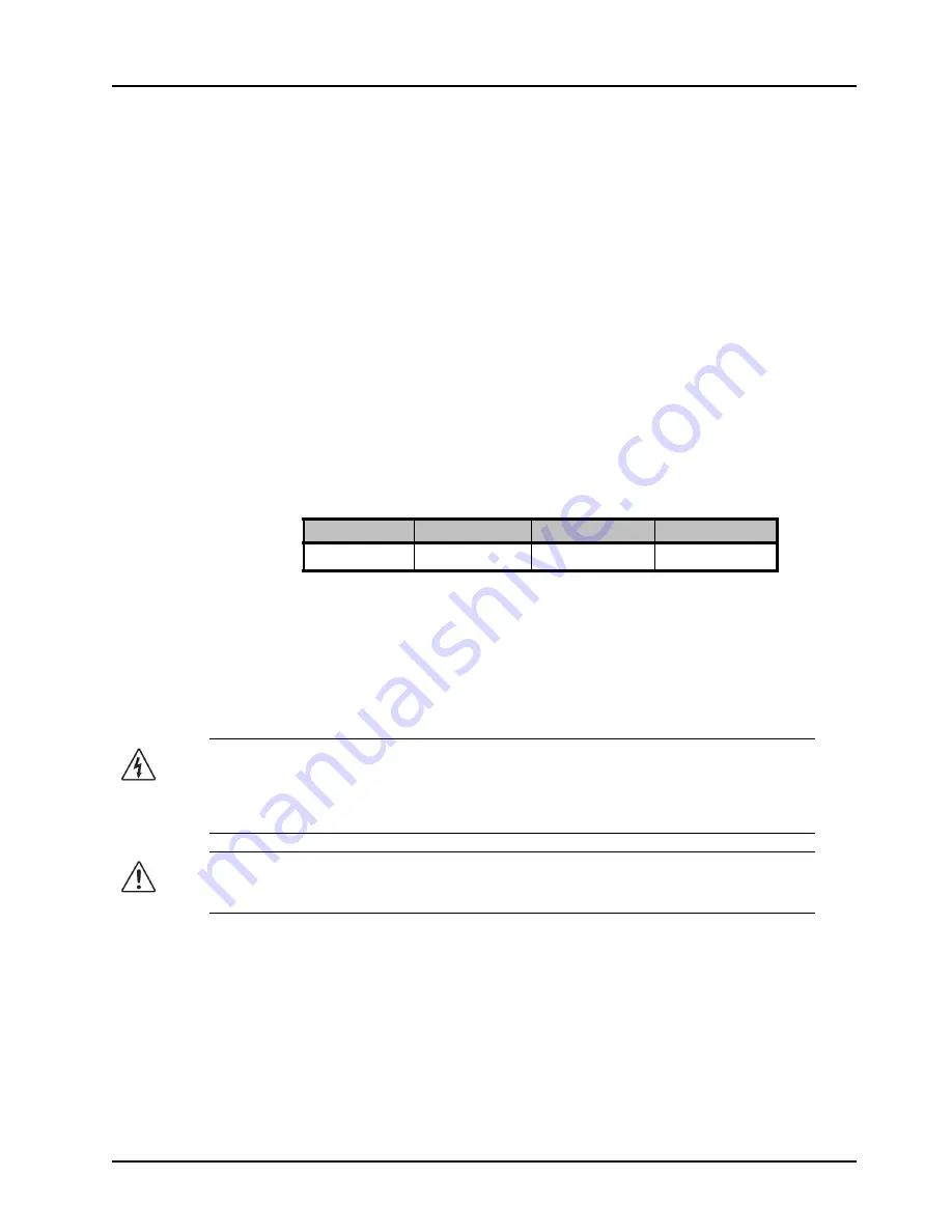
Table 2.1  Frame Dimensions

Rack Units

Height

Depth

Width

2 RU

3.5” (8.89cm)

8.5” (21.59cm)

19” (48.26cm)

Warning Hazardous Voltages

 — The safe operation of this product’s external 

power supply requires that a protective earth connection be provided. This protective 
earth is provided by the grounding conductor in the equipment's supply cord. To reduce 
the risk of electrical shock to operator and service personnel, this ground conductor must 
be connected to an earthed ground.

Warning 

— In some countries, it may be necessary to supply the correct mains supply 

cord. Use only an approved IEC 320 C-13 type A/C line cord rated for a minimum 10A at 
250V and certified for the country of use.

Summary of Contents for MB-650

Page 1: ...MB 650 Monitoring Bridge User Manual...

Page 2: ...eople that make things happen At Ross our employees are a special group Our employees truly care about doing a great job and delivering a high quality customer experience every day This code of ethics...

Page 3: ...retrieval system or transmitted in any form or by any means mechanical photocopying recording or otherwise without the prior written permission of Ross Video While every precaution has been taken in t...

Page 4: ...or electric shock do not expose this apparatus to rain or moisture Protective Earth This symbol identifies a Protective Earth PE terminal which is provided for connection of the supply system s prote...

Page 5: ...other relevant provisions of CE Directive 93 68 EEC AUSTRALIA This equipment has been tested to AS NZS CISPR 22 2009 and found to comply with the limits for a Class A Digital device INTERNATIONAL This...

Page 6: ...ral resources Ross Video encourages you to use the appropriate take back systems These systems will reuse or recycle most of the materials from your end of life equipment in an environmentally friendl...

Page 7: ...1K0 Ogdensburg New York Canada USA 13669 0880 General Business Office 1 613 652 4886 Fax 1 613 652 4425 Technical Support 1 613 652 4886 After Hours Emergency 1 613 349 0006 E mail Technical Support t...

Page 8: ......

Page 9: ...650 2 6 SDI Cabling 2 6 Configuration 3 Using the Front Panel Display 3 2 Using DashBoard 3 3 To launch DashBoard 3 3 To access the MB 650 interfaces 3 3 Network Configuration 3 4 Automatic Configura...

Page 10: ...Iss 01 MB 650 Interface 4 4 Status Tab 4 4 Product Tab 4 4 Settings Tab 4 5 Specifications 5 Technical Specifications 5 2 Service Information 6 Troubleshooting Checklist 6 2 Warranty and Repair Polic...

Page 11: ...deo products which are backed by over 25 years of engineering and design expertise You will be pleased at how easily your new Monitoring Bridge fits into your overall working environment Equally pleas...

Page 12: ...de intuitive channel source and mode selection Also located on the front panel is a push to mute rotary shaft encoder for volume control and a 1 4 long frame jack for headset monitoring High quality f...

Page 13: ...ction provides a functional block diagram for the MB 650 Figure 1 1 MB 650 Simplified Block Diagram SDI Video In SDI Video Out 16 Channel DMX VFD 16 VU Peak Meters LKFS Meter 16 CHANNELS SDI EQ and Re...

Page 14: ...adjusting the volume level for the speakers For More Information on configuring the MB 650 for network communication refer to the section Network Configuration on page 3 4 menus in DashBoard for the M...

Page 15: ...lation 2 1 Installation In This Chapter This chapter provides instructions for the physical installation of your MB 650 and basic cabling for the MB 650 Before You Begin Front Panel Overview Rear Pane...

Page 16: ...container and ensure that all items are included If any items are missing or damage contact your sales representative or Ross Video directly ESD Susceptibility Static discharge can cause serious dama...

Page 17: ...trol the volume Push the knob to mute the audio 3 Source Select Buttons This row of eight push buttons enable you to route the corresponding source to the speakers of the MB 650 Refer to the section C...

Page 18: ...el that is used for communication with DashBoard and software upgrades via DashBoard 6 Power Supply Connections These are the connectors for the primary PSU1 and optional redundant PSU2 supplies 7 Pow...

Page 19: ...le of working with all world AC standards 100 240V This section includes information for connecting the power cables for the MB 650 To connect the power cables for the MB 650 1 For each power cable in...

Page 20: ...our IT Department before connecting to your facility network to ensure that there are no conflicts They will provide you with an appropriate value for the IP Address Subnet Mask and Gateway for the MB...

Page 21: ...In This Chapter This chapter provides instructions to configure basic communications for your MB 650 The following topics are discussed Using the Front Panel Display Using the Front Panel Display Net...

Page 22: ...ITU 1770 LKFS numerical read out of the true peak PK 5 Signal Data Display This area includes the following fields SIG field Displays the type of SDI signal GRP field Indicates which groups of audio...

Page 23: ...Slot 1 node enables you to set up the audio features for the physical panel To launch DashBoard 1 Ensure that you are running DashBoard software version 6 0 0 or higher The software and DashBoard Use...

Page 24: ...the factory default values If all cables are connected and the LEDs do not indicate an error then automatic configuration is not possible Custom User Configuration via DashBoard Once communication has...

Page 25: ...B 650 To set a new Mater Password for the MB 650 1 From the Tree View right click the node for the MB 650 you want to access 2 Select Lock Unlock Access to display the Change Master Password dialog 3...

Page 26: ...ser to select the embedded audio pairs Mode Selection The four push buttons located to the right side of the source selection switches are for the mode selection Table 3 1 Mode Selection Mode Descript...

Page 27: ...log box This dialog box displays the selected upload file name type size and the file creation date 8 From the Confirmation dialog box select one of the following Cancel Select this option to cancel t...

Page 28: ...3 8 Configuration MB 650 User Manual Iss 01...

Page 29: ...le for the MB 650 Default values are indicated with an asterisk The DashBoard Control System enables you to setup an IP address for the MB 650 and monitor its status from a computer You can download t...

Page 30: ...Items Tab Title Item Parameters Description Current Settings Network Source DHCP set by user The Addressing Mode is set to DHCP in DashBoard The network automatically assigns the MB 650 ethernet sett...

Page 31: ...em Parameters Description Network NTP Server This is the IP Address of the NTP server used as a time source Addressing Mode Static User defines the Network settings of the card DHCP DashBoard obtains...

Page 32: ...eo Status Locked Green MB 650 is locked to the input signal Unlocked Red MB 650 is not locked to the input signal SDI Format Indicates the input video format LKFS dBFS Indicates ITU 1770 LKFS numerica...

Page 33: ...Settings Tab Items Tab Title Item Parameters Description Settings Input Source Specifies the audio channel to route to the speakers Mode Stereo Outputs the channel pair SUM Allows any of the channels...

Page 34: ...4 6 DashBoard Menus MB 650 User Manual Iss 01...

Page 35: ...ions 5 1 Specifications In This Appendix This appendix provides information on the specifications for your MB 650 Note that specifications are subject to change without notice The following topics are...

Page 36: ...Reclocked SMPTE 259M SMPTE 292M SMPTE 424M Connector Type 75ohm BNC Signal Level 800mV nominal Return Loss 10dB to 3G Analog Audio Monitor Output Number of Outputs 2 Connector Type 3 pin terminal blo...

Page 37: ...MB 650 User Manual Iss 01 Service Information 6 1 Service Information In This Chapter This chapter contains the following sections Troubleshooting Checklist Warranty and Repair Policy...

Page 38: ...Review Performing a quick visual check may reveal many problems such as connectors not properly seated or loose cables Check the MB 650 and any associated peripheral equipment for signs of trouble 2 P...

Page 39: ...This MB 650 User Manual provides all pertinent information for the safe installation and operation of your MB 650 Ross Video policy dictates that all repairs to the MB 650 are to be conducted only by...

Page 40: ...trade show information Visit Us Visit our website for Company information and news Related products and full product lines Online catalog Testimonials Technical Support Telephone 1 613 652 4886 After...

Reviews: