


but the power supplies in the control panel require the
panel to be powered off.
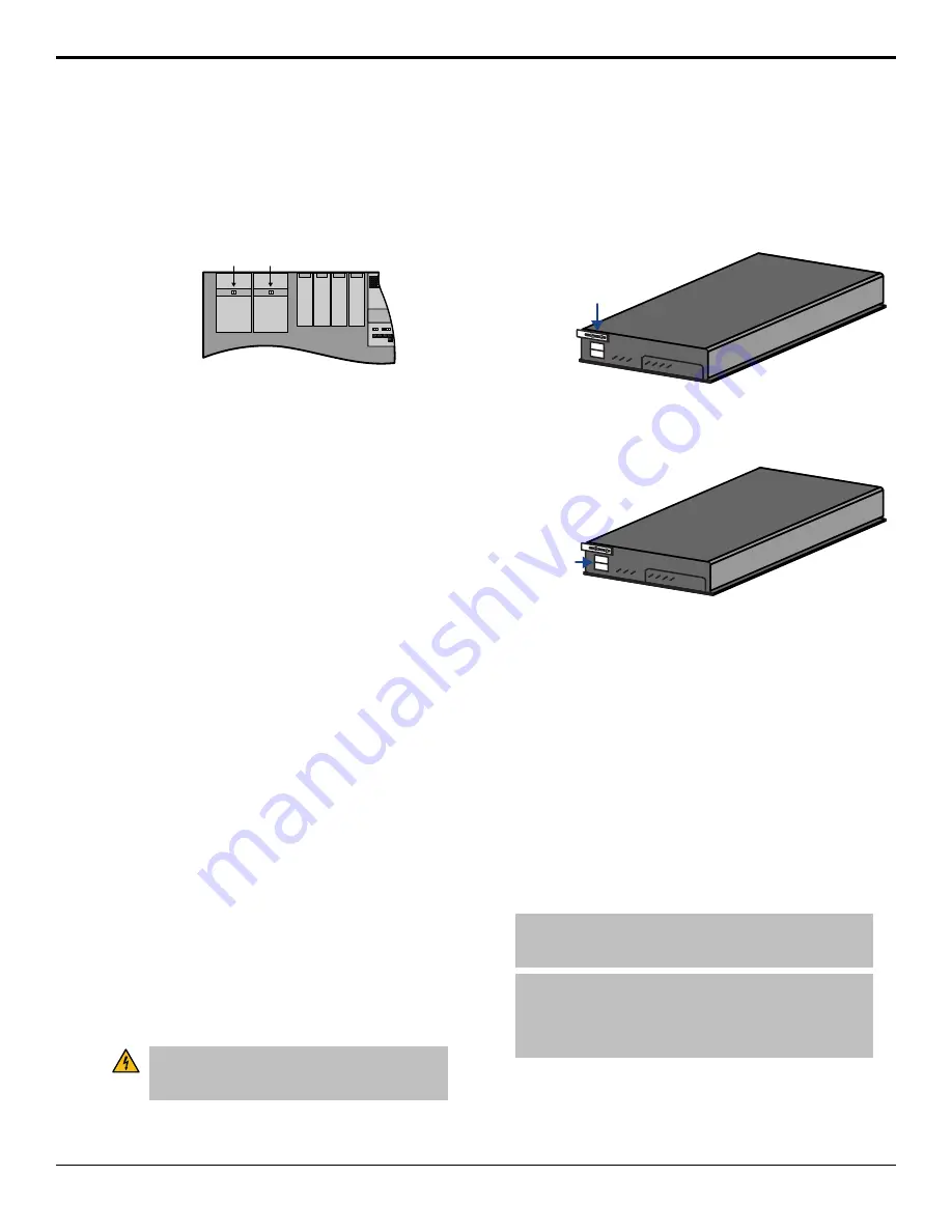
To Replace a Control Panel Power Supply
1.
Toggle the Primary and, if installed, Secondary AC
Power switches for the control panel to OFF.
Primary
Power
Supply
Module
Secondary
Power
Supply
Module
Power
Switch
Power
Switch
2.
Disconnect the AC power cords from the back of
the Power Supply module that contains the failed
power supply.
3.
Label and remove the Power Supply Status cables
and Power Supply cables for each power supply in
the Power Supply module before you remove them.
If there is only power supply in the module, you do
not need to label the cables.
4.
Disconnect the Power Supply Status cables and
Power Supply Power cables for the power supplies
in the Power Supply module that you want to
remove.
5.
Remove the 2 retaining screws along the front flange
of the Power Supply module.
6.
Slide the failed Power Supply module out of the
control panel tub and place on a clean, dry surface.
7.
Slide the new Power Supply module into the open
slot in the control panel tub that you just removed
the failed Power Supply module from.
8.
Replace the 2 retaining screws along the front flange
of the Power Supply module.
9.
Reconnect the Power Supply Status cables and
Power Supply Power cables for each power supply
in the Power Supply module.
10.
Reconnect the AC power cords to the back of the
Power Supply module.
To Replace a Frame Power Supply
The power supplies in the frame are hot-swappable only
if the Redundant Power option is installed. If you do not
have redundant power supplies, you must power down
the frame before attempting to remove a power supply.
Warning Hazardous Voltages:
Hazardous voltages
are present in this device as long as any of the power
supplies are connected to the AC power.
1.
Remove the front door of the frame.
2.
Locate the power supply to be replaced.
3.
Switch the power supply Off by toggling the power
switch down.
4.
Loosen the 2 screws holding the latch in place and
move the latch so that you can remove the power
supply.
Power Supp
ly
Latch
Screws
5.
Remove the failing power supply.
6.
Verify that all the power supplies are switched off
before installing them into the frame.
Power Supp
ly
Power
Switch
7.
Install the new power supply into the slot that you
removed the old power supply from.
8.
Secure each power supply into the frame by moving
the latch to the left until it hooks the slot edge and
tighten the screws.
9.
Switch the new power supply On.
The switcher will automatically detect the new
power supply and clear the fail message.
Replacing a Frame Board
Boards can be installed or replaced in the frame to
increase the available resources of your switcher, or
replace a failing component. With the exception of the
Frame CPU, all boards in the frame are hot-swappable.
Note:
Any resources provided by that board will be lost when
the board is removed. For example, if you remove the Crosspoint
board there will be no video routing in the frame.
Note:
If you are replacing a Video Input board with a
MultiProcessor Input board, ensure that all of the inputs are set
to the same format that the switcher is operating in. If an input
is not set to the same format that the switcher is operating, the
MultiProcessor Input board may become unresponsive.
Acuity Setup Manual (v9.2) — Switcher Maintenance •
107
Summary of Contents for Acuity 4410AR-020
Page 1: ...Acuity Setup Manual v9 2...


