Rosen Aviation
MIP
Document Number: 109970
Page 6 of 12
Revision A
Date: 04/24/18
2.5. Connections
2.5.1. MIP uses the following connections and inputs.
Figure 2: MIP view from Rear (MIP100-002 shown & MIP100-003 similar)
Pay close attention to the pinout descriptions on the MIP Outline and Installation
Drawings to assist in completing the wiring connections.
Note:
Do Not Hot plug this connector.
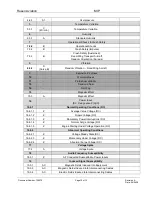
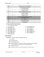
2.5.2. MIP I/O & Strapping Connector (J1) Pin-out Logic and Function
Table 1: I/O & Strapping Logic and Function
MIP P/N MIP100-002 & MIP100-003
PIN
FUNCTION
1
Return 28 VDC
2
28 VDC in
3
3G / HD Control in**
4
Chassis GND
5
HD Analog Audio Out Right
6
N/C
7
Signal GND
8
N/C
9
N/C
10
HD Analog Audio Out Left
11
USB VBUS
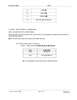
J1 MIP I/O & Strapping
Connector
J2 & J3.
HD BNC 3G SDI outputs
Note: Both outputs are identical


