background image

10-00328 REV C 

7.2  INSTALLATION 

The Q-LED II can be operated at any attitude.  The unit should be installed by securely 
mounting  the  light  housing  to  a  stable  surface.  The  threaded  ¼-  20  tapped  mounting 
holes are an integral feature of the Q-LED II; mounting clamps are not required.  Refer 
to  installation outline drawing (ROS P/N  10-00369) for specific installation dimensions.  
If  mounting  brackets  are  required  for  your  application,  QL  brackets  are  available  for 
purchase  (ROS  P/N  70-08251-01),  and  allow  the  light  to  easily  be  oriented  in  any 
direction. 


7.3  INTERCONNECTION 

Interconnection is made  via the underwater connector.  To mate the connector, 

TURN 

POWER OFF

, clean both halves of the connector, lubricate the mating connector lightly 

with food grade silicone spray, and push together. 
 
The other end of the cable attaches to the required power source 

8  MAINTENANCE  

The  Q-LED  II  is  designed  as  a  zero  maintenance  lamp.  Please  contact  ROS  or  an 
authorized sales rep. if you have any questions.   

APPENDIX 

 
10-00369 


Installation Outline Drawing, Q-LED III and II 

70-08251 


Bracket, LED, QL, Al 


Summary of Contents for Q-LED II

Page 1: ...OLID STATE UNDERWATER LED LAMP Q LED II 120VAC 160VDC OPERATING AND MAINTENANCE MANUAL SERIAL NUMBER __________ SALES ORDER __________ 5618 Copley Drive San Diego CA 92111 7902 TEL 858 565 8500 FAX 85...

Page 2: ...is warranty shall be governed by the laws of the State of California In the event the defect is determined to be within the terms of this warranty then ROS agrees to repair and or replace at ROS s dis...

Page 3: ...and are able to provide assistance during installation and or operation of these products If you have any questions or problems with this product that are not covered by this manual or instruction pl...

Page 4: ...ATION 3 3 1 POWER 3 3 2 TEMPERATURE PROTECTION 3 3 3 RECOMMENDED OPERATION 3 4 SPECIFICATIONS 3 4 1 ELECTRICAL 3 4 2 PERFORMANCE 4 4 3 MECHANICAL 6 4 4 ENVIRONMENTAL 6 5 VIDEO COMPATIBILITY 6 6 CONNEC...

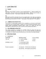
Page 5: ...e Q LED II Like a conventional lamp light dimming is achieved by decreasing or increasing the input source voltage Lights powered by AC voltage can be dimmed using an AC phase control dimmer If powere...

Page 6: ...a solid state LED light array The LED light engine is secured in the housing via a special assembly The forward end of the Q LED II is sealed with an o ring between the housing and a deepwater rated w...

Page 7: ...t off switch The light will run for approximately 4 minutes in air at an ambient temperature of 20 C 68 F before automatically powering down There is no reset the light will automatically re illuminat...

Page 8: ...original maximum output Dimming AC Powered Light is dimmed via input voltage or AC phase control DC Powered Light is dimmed via input voltage or PWM A modulation frequency of 1 kHz or higher is recom...

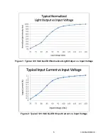
Page 9: ...10 00328 REV C 5 Figure 1 Typical 120 VAC Q LED II Normalized Light Output vs Input Voltage Figure 2 Typical 120 VAC Q LED II Input Current vs Input Voltage...

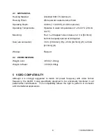
Page 10: ...olt circle equally spaced at 90 degrees Size w o connector 7 61in 193 4mm H x 2 50in 63 5mm W x 2 50in 63 5mm D Window Flat port 4 4 ENVIRONMENTAL Weight in Air 3 65 lb 1 66 kg Weight in Water 1 93 lb...

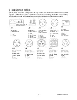
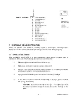
Page 11: ...1 Load 2 Neutral 3 Earth Ground 04 XSG 3BCL HP SS ROS 60 01122 4 1 Earth Ground 2 Load 3 Neutral 05 LPBH 3 MP ROS 60 01010 4 1 Load 2 Neutral 3 Earth Ground 06 BH 3 MP W LOCK SLEEVE ROS 60 04080 4 1...

Page 12: ...nt to the mating connector and carefully attach it to the bulkhead connector 4 Apply 120VAC 50 60Hz power and observe the lamp emit light 5 If you notice any issues with the functionality of the light...

Page 13: ...s are available for purchase ROS P N 70 08251 01 and allow the light to easily be oriented in any direction 7 3 INTERCONNECTION Interconnection is made via the underwater connector To mate the connect...

Reviews: