background image


2


USING THE UNIT SAFELY


001


Before using this unit, make sure to read the 
instructions below, and the Owner’s Manual.


................................................................................................


002a


Do not open or perform any internal modifications 
on the unit.


................................................................................................


003


Do not attempt to repair the unit, or replace parts 
within it (except when this manual provides 
specific instructions directing you to do so). Refer 
all servicing to your retailer, the nearest Roland 
Service Center, or an authorized Roland 
distributor, as listed on the “Information” page.


................................................................................................


004


Never use or store the unit in places that are:
• Subject to temperature extremes (e.g., direct 

sunlight in an enclosed vehicle, near a heating 
duct, on top of heat-generating equipment); or 
are

• Damp (e.g., baths, washrooms, on wet floors); or 

are

• Humid; or are
• Exposed to rain; or are
• Dusty; or are
• Subject to high levels of vibration.


................................................................................................


007


Make sure you always have the unit placed so it is 
level and sure to remain stable. Never place it on 
stands that could wobble, or on inclined surfaces.


................................................................................................


011


Do not allow any objects (e.g., flammable material, 
coins, pins); or liquids of any kind (water, soft 
drinks, etc.) to penetrate the unit.


................................................................................................


013


In households with small children, an adult should 
provide supervision until the child is capable of 
following all the rules essential for the safe 
operation of the unit.


................................................................................................


014


Protect the unit from strong impact.
(Do not drop it!)


................................................................................................


104


Try to prevent cords and cables from becoming 
entangled. Also, all cords and cables should be 
placed so they are out of the reach of children.


................................................................................................


106


Never climb on top of, nor place heavy objects on 
the unit.


................................................................................................


118a


Should you remove nuts, washers, screws, anchor 
bolts, etc., keep them in a safe place out of 
children’s reach, so there is no chance of them 
being swallowed accidentally.


................................................................................................

Used for instructions intended to alert 
the user to the risk of injury or material 
damage should the unit be used 
improperly. 

* Material damage refers to damage or 

other adverse effects caused with 
respect to the home and all its 
furnishings, as well to domestic 
animals or pets. 

Used for instructions intended to alert 
the user to the risk of death or severe 
injury should the unit be used 
improperly. 

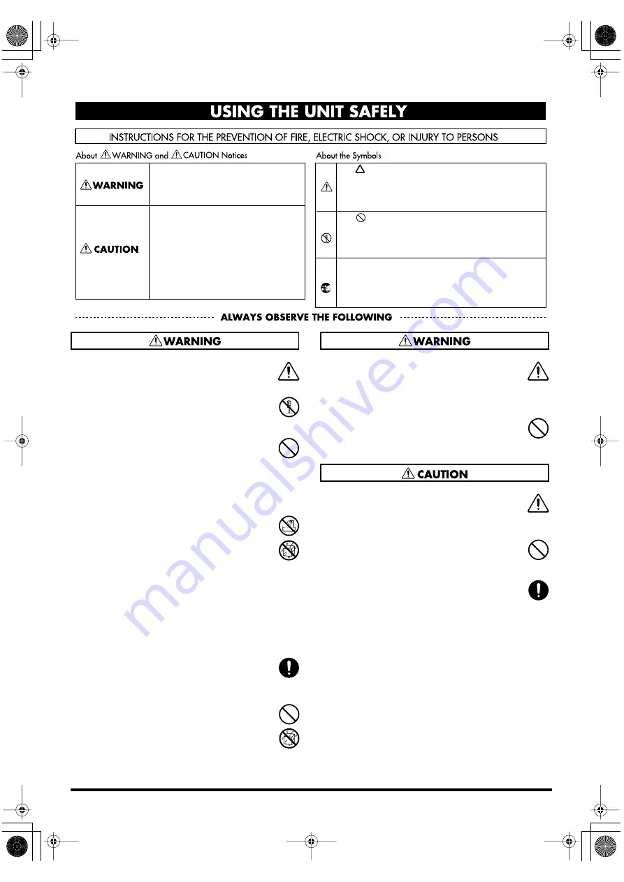
The 

  symbol alerts the user to things that must be 

carried out. The specific thing that must be done is 
indicated by the design contained within the circle. In 
the case of the symbol at left, it means that the power-
cord plug must be unplugged from the outlet. 

The      symbol alerts the user to important instructions 
or warnings.The specific meaning of the symbol is 
determined by the design contained within the 
triangle. In the case of the symbol at left, it is used for 
general cautions, warnings, or alerts to danger. 

The       symbol alerts the user to items that must never 
be carried out (are forbidden). The specific thing that 
must not be done is indicated by the design contained 
within the circle. In the case of the symbol at left, it 
means that the unit must never be disassembled. 

TD-3KV_e 2 ページ 2004年12月16日 木曜日 午後3時43分

Summary of Contents for V-Drums TD-3KV

Page 1: ...is unit carefully read the sections entitled USING THE UNIT SAFELY and IMPORTANT NOTES p 2 p 3 These sections provide important information concerning the proper operation of the unit Additionally in order to feel assured that you have gained a good grasp of every feature provided by your new unit Owner s manual should be read in its entirety The manual should be saved and kept on hand as a conven...

Page 2: ... becoming entangled Also all cords and cables should be placed so they are out of the reach of children 106 Never climb on top of nor place heavy objects on the unit 118a Should you remove nuts washers screws anchor bolts etc keep them in a safe place out of children s reach so there is no chance of them being swallowed accidentally Used for instructions intended to alert the user to the risk of i...

Page 3: ...e This way you will avoid causing shorts or damage to the cable s internal elements 558c Since sound vibrations can be transmitted through floors and walls to a greater degree than expected take care not to allow such sound to become a nuisance to neighbors especially at night and when using headphones Although the drum pads and pedals are designed so there is a minimal amount of extraneous sound ...

Page 4: ...e FD 8 package The TD 3 Owner s Manual is included in the TD 3 package This package does not include a kick pedal Use with a commercially available kick pedal 962a In the interest of product improvement the specifications and or appearance of this unit are subject to change without prior notice Assemble the Drum Stand About the Stand refer to the owner s manual for the stand Check the Contents of ...

Page 5: ... and use them Use of other screws may result in damage to the unit 928 When turning the unit upside down get a bunch of newspapers or magazines and place them under the four corners or at both ends to prevent damage to the buttons and controls Also you should try to orient the unit so no buttons or controls get damaged 929 When turning the unit upside down handle with care to avoid dropping it or ...

Page 6: ...page Use this as a reference when making the adjustment Tighten each tuning bolt one by one observing the numerical order shown in the diagram Do not firmly tighten a single tuning bolt by itself Doing so will make it impossible to tension the head evenly and will cause malfunctions such as failure to accurately detect the striking location fig PD 85 Head2 2 Fine tune the adjustment while continui...

Page 7: ...OFF On the other hand if you find it difficult to get rim shot sounds to play raise the Rim Sensitivity value For details refer to the TD 3 Owner s Manual p 59 Cross Stick fig PD 85 XS e_90 The cross stick sound is sometimes referred to as a closed rim shot When using the PD 85BK to play the cross stick be sure that you only strike the rim outer edge of the pad Placing your hand on the head center...

Page 8: ...on the frame 5 Place the hoop onto the head 6 Pass the tuning bolts through the washers then attach them to the hoop and frame 7 Next adjust the tension of the head p 6 About the Lock Bushings The PD 85BK is provided with lock bushings to prevent rotation and loosening of the tuning bolts caused by vibration transmitted from the hoop as the result of using rim shots or other performance techniques...

Page 9: ... Hat fig PD BE e Hitting the head is like playing the bow of the hi hat and hitting the rim is like playing the edge of the hi hat cymbals PD 8 Pad Pad Size 8 5 inches Triggers 2 Head Rim Dimensions 226 W x 280 D x 54 H mm 8 15 16 W x 11 1 16 W x 2 1 8 H inches Weight 1 2 kg 2 lbs 11 oz PD 8 Pad Attaching the Pad to a Stand Stand Fixing Screw Stand Fixing Screw Head Output Jack Tighten Loosen Rod ...

Page 10: ...It corresponds to the sound of the rim side of the connected trigger input To make use of edge shot you ll need to connect to a trigger input jack on the percussion sound module that accommodates rim shots fig CY Edge e Choking Choking pinching the cymbal s edge with the hand immediately after hitting the cymbal makes the sound stop To make use of choking play techniques you ll need to connect to ...

Page 11: ...Closed Hi Hat Strike the hi hat with the pedal pressed Foot Closed Completely press down the pedal The volume of the Foot Closed sound can be adjusted separately TD 3 Owner s Manual p 42 Connect the FD 8 to the TD 3 before turning on the power Do NOT press the pedal when turning on the power FD 8 Hi Hat Control Pedal Dimensions 130 W x 396 D x 103 H mm 5 1 8 W x 15 5 8 D x 4 1 16 H inches Weight 1...

Page 12: ...kes the center of the head then secure the kick pedal and KD 8 firmly in place fig KD Assy04 e Adjusting the Foot Plate Height Depending on your kick pedal it can be unstable when you attach it to the KD 8 Be sure to adjust the foot plate height so that the entire bottom surface of the pedal is attached to the floor fig KD Assy05 e KD 8 Kick Trigger Pad Making the Settings Anchor Bolt Head Foot Pl...

Page 13: ... pedal in place this will make it easier to use the kick pedal However when used on flooring the anchor bolts may damage the floor Adjust the anchor bolts correctly fig KD Anchor e The tips of the anchor bolts are sharp Handle with care When Using a Twin Pedal fig KD Pedal1 Position the two beaters equally apart from the center of the pad as shown in the figure at left If one of the beater is furt...

Page 14: ...fig Setting1 e fig Label 1 Insert the plugs of connecting cables into the TRIGGER INPUT jacks on the rear of the TD 3 2 Insert the other plugs opposite ends into the TRIGGER OUTPUT jacks of the pads When you connect the cables please refer to the labels that are attached to both ends of the cables Set the trigger type for trigger input SNARE to TD 3 Owner s Manual p 50 Assemble the TD 3KV HHC KIK ...

Page 15: ...TD 3KV_e 15 ページ 2004年12月16日 木曜日 午後3時43分 ...

Page 16: ...03898823 1PR TD 3KV_e 16 ページ 2004年12月16日 木曜日 午後3時43分 ...

Reviews: