background image

83

Menu List

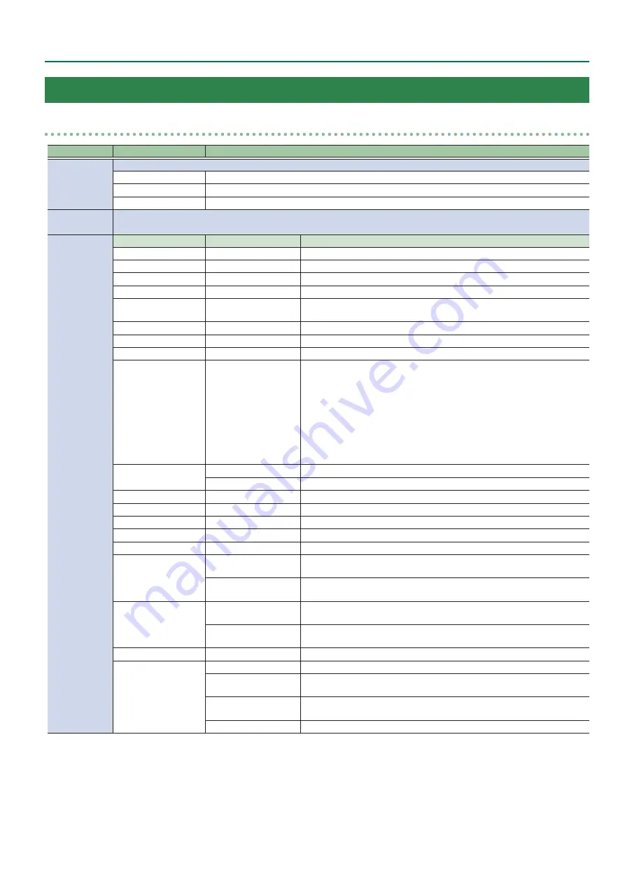
17: CTL/EXP

CTL/EXP 1, 2

Menu item

Value 

(Bold: default)

Explanation

CTL/EXP TYPE

Specifies the device (footswitch, expression pedal) that is connected to the CTL/EXP jack.

OFF

Disables the CTL/EXP jack.

CTL A & CTL B

Choose this if a footswitch is connected.

EXP

Choose this if an expression pedal is connected.

ASSIGN

Specifies the functions that are assigned to CTL A and CTL B of the footswitch.
* This is valid when “CTL/EXP TYPE” is set to “CTL A & CTL B.”

CTL A
CTL B

CATEGORY

VALUE

Explanation

N/A

---

No function is assigned.

A/PGM CH SELECT

INPUT 1–8

Switches the video sent to the A/PGM bus.

B/PST CH SELECT

INPUT 1–8

Switches the video sent to the B/PST bus.

AUX CH SELECT

INPUT 1–8

Switches the video sent to the AUX bus.

INPUT ASSIGN

INPUT 1–8

Each time you press the footswitch, the video source of the specified input 

channel switches.

STILL OUTPUT

STILL 1–8

Pauses the normal output, and preview/final outputs a cut of the still image.

PinP 1, 2 SOURCE

HDMI 1–8, STILL 1–8

Switches the video shown in the PinP 1 or PinP 2 inset screen.

DSK SOURCE

HDMI 1–8, STILL 1–8

Switches the DSK video source.

SW CONTROL

CUT SW, AUTO SW
TRANSITION SW
MODE SW
SPLIT/VFX A, B SW
PinP 1, 2 PVW SW
PinP 1, 2 ON SW
DSK PVW SW
DSK ON SW
USER 1, 2 SW

This works the same as when you press the button selected in “VALUE.”

TAKE

H

 AUTO TAKE 

I

Automatically switches the A/ PGM/ bus and B/PST bus videos.

H

 CUT 

I

Switches the video between PGM/A bus and PST/B bus as a cut.

AUDIO INPUT MUTE

HDMI IN 1–8, AUDIO IN Turns the mute function on/off for the input audio.

AUDIO OUTPUT MUTE MASTER OUTPUT, AUX

Turns the mute function on/off for the output audio.

AUDIO INPUT SOLO

HDMI IN 1–8, AUDIO IN Turns the solo function on/off for the input audio.

OUTPUT FADE

LEFT, RIGHT

The same function as turning the [OUTPUT FADE] knob to the left or right.

LOAD MEMORY

MEMORY 1–24

Recalls a preset memory.

INPUT SCAN

NORMAL

Each time you press the footswitch, the final output switches from INPUT 

1–8 in sequential order.

REVERSE

Each time you press the footswitch, the final output switches from INPUT 

1–8 in reverse order.

MEMORY SCAN

NORMAL

Each time you press the footswitch, preset memories 1–24 are recalled in 

sequential order.

REVERSE

Each time you press the footswitch, preset memories are recalled in reverse 

order from 24 through 1.

MACRO EXECUTE

MACRO 1–100

Executes a macro (a series of recorded operations).

SEQUENCER

MODE ON/OFF

Turns sequencer function on/off.

NEXT

When the sequencer function is on, the same operation as when you press 

the [AUTO] button.

PREVIOUS

When the sequencer function is on, the same operation as when you press 

the [CUT] button.

AUTO SEQUENCE

Turns the auto sequence function on/off.

Summary of Contents for V-8HD

Page 1: ...pecific Audio Mute 39 Checking a Specific Audio Input Solo 40 Other Features 41 Saving Recalling Settings Preset Memory 41 Recording Multiple Operations to Automatically Execute Macros 46 Combining Preset Memories and Macros for Operations Sequencer 53 Saving the Unit s Settings on a USB Flash Drive 59 Formatting USB Flash Drives 60 Using a Footswitch 61 Using an Expression Pedal 62 Assigning the ...

Page 2: ...ink Currently switching video Unlit DSK composition off Name Explanation 5 PinP 1 POSITION H knob During PinP 1 compositing this adjusts the horizontal display position of the inset screen POSITION V knob During PinP 1 compositing this adjusts the vertical display position of the inset screen PVW button When this is on lit it makes the PinP 1 compositing results the preview output ON button Switch...

Page 3: ... VFX B button If this is on lit the effect of split visual effect B is applied to the video selected by the Cross point B 1 8 buttons If the SPLIT VFX type is set to split it is not possible to turn both A and B on 10 A PGM B PST Cross point A 1 8 buttons Selects the video to input to bus A of the video mixer The selected button lights up When the SPLIT VFX A button is on the split visual effect A...

Page 4: ...ng equipment and external displays The V 8HD menu is shown on the display that s connected to the OUTPUT 3 connector HDMI input connector REMOTE port You can use a commercially available connection cable or adaptor cable Lightning USB camera adaptor to connect an iPad and remotely control the V 8HD CTL EXP 1 2 jacks Connect footswitches sold separately BOSS FS 6 etc or expression pedals sold separ...

Page 5: ... Stereo 1 4 phone type Stereo 1 4 phone type FS 7 Stereo 1 4 phone type Stereo 1 4 phone type CTL B CTL A TIP RING CTL EXP 1 CTL EXP 2 NOTE The BOSS FS 6 s A B and A B jacks also act as the power switch The power turns on when you insert a plug into the jack and turns off when you remove the plug To prevent the batteries from running down remove the plugs from the jacks when you re not using the B...

Page 6: ...isplays a audio level meter The indicators for the level meter are the same as for AUDIO OUT 2 Indicates the function selected by the MODE button Indicator Explanation Green AUX AUX bus selected Yellow PinP 1 SOURCE PinP 1 source screen selected Magenta PinP 2 SOURCE PinP 2 source screen selected 3 The REC indicator is shown If a camera that supports the HDMI REC TRIGGER function is connected this...

Page 7: ...you do not want the power to be turned off automatically disengage the Auto Off function Press the MENU button 0 SYSTEM 0set AUTO OFF to OFF Unsaved data is lost when the power turns off Before turning the power off save the data that you want to keep To restore power turn the power on again Using the Menus This explains how to display menus and make settings for video and for the V 8HD itself The...

Page 8: ...ssing is progressive Interlaced input video is automatically converted to a progressive signal The picture might appear jagged at this time or the picture in a PinP inset screen or on the multi view monitor might waver This is due to progressive conversion and is not a malfunction About frame rates To change the V 8HD s frame rate press the MENU button0 SYSTEM 0 FRAME RATE Setting the Input Format...

Page 9: ...e s how to adjust the character of the video that s input to INPUT 1 8 For INPUT 7 and 8 connectors you can also adjust the scaling 1 Press the MENU button0 VIDEO INPUT 0 select one of INPUT 1 to INPUT 8 SCALER and press the VALUE knob A menu for the selected input video appears 2 Select a menu item then turn the VALUE knob to adjust the input video and press the VALUE knob Menu item Explanation I...

Page 10: ...hing AUX Output p 16 About audio outputs assigned to video buses Changing an video bus assignment makes the output audio also change in tandem according to the assigned bus Video bus assignment Output audio PROGRAM PREVIEW MULTI VIEW Outputs the audio of the MASTER OUTPUT bus AUX Outputs the audio of the AUX bus You can also fix the output audio to the MASTER OUTPUT bus or AUX bus regardless of th...

Page 11: ...OPERATION and press the VALUE knob 2 Use the VALUE knob to select A B or PGM PST and press the VALUE knob 3 Press the MENU button to quit the menu Using Mix Wipe to SwitchVideo When A B mode The video at the end to which the video fader is flipped is always the final output 1 Flip the video fader all the way upward or downward Transition indicators 2 Press a Cross point 1 8 button at the end to wh...

Page 12: ...IX TYPE Specifies the transition pattern for mix WIPE TYPE Specifies the transition pattern for wipe WIPE DIRECTION Specifies the direction of wipe WIPE BORDER COLOR Specifies the color of the border added to the edge of the wipe area WIPE BORDER WIDTH Exchanges the colors 3 Use the VALUE knob to change the value and press the VALUE knob For details about these values refer to p 67 4 Press the MEN...

Page 13: ...When the video of the B PST bus is selected switches to the video of the A PGM bus H CUT When the video of the B PST bus is selected switches to the video of the A PGM bus as a cut H TRANSFORM Switches to the video of the A PGM bus as a cut only while you hold down the button Function Explanation AUTO SW ASSIGN AUTO TAKE I When the video of the A PGM bus is selected switches to the video of the B ...

Page 14: ...atically switches the video at specified BPM intervals This lets you create video transitions that are synchronized with the music for example when live streaming a DJ performance or a musical performance Turning the auto switching function on off 1 Press the AUTO SWITCHING button to turn the auto switching function on lit Indicator Explanation Green Input scan Blue Preset memory scan Red BPM sync...

Page 15: ...own 4 Use the VALUE knob to change the value and press the VALUE knob 5 Press the MENU button to quit the menu BPM sync 1 Press the MENU button0 AUTO SWITCHING 0 select TYPE and press the VALUE knob 2 Use the VALUE knob to select BPM SYNC and press the VALUE knob 3 Use the VALUE knob to select a menu item and press the VALUE knob Menu item Explanation BPM Specifies the BPM MODE Specifies how the p...

Page 16: ... Unlit No video is input Sending the same video as the PGM output to the AUX output By using the AUX link function you can send the same video as the PGM bus the final output video to the AUX bus 1 Press the MENU button0 SYSTEM 0select AUX LINKED PGM and press the VALUE knob 2 Use the VALUE knob to select AUTO LINK or MANUAL LINK and press the VALUE knob If you re not using the AUX link function t...

Page 17: ...e displayed position of the video and change the color or width of the border For details refer to p 68 of Menu list Compositing Using Split 1 Press a Cross point A 1 8 button to select the video you want to display above or on the left 2 Press a Cross point B 1 8 button to select the video you want to display below or on the right 3 Press the SPLIT VFX A or B button to turn on SPLIT lighted The v...

Page 18: ... controlling the brightness 4 Press the MENU button to quit the menu ApplyingVisual Effects 1 Press a Cross point A or B 1 8 button to output the video to which you want to apply the effect 2 Press the SPLIT VFX A or B button to turn on the visual effect making the button light up The visual effect is applied to the output video 3 Use the SPLIT VFX A or B knob to adjust the degree of effect applie...

Page 19: ...ing lit The PinP 1 ON button lights up in red and the inset screen is composited onto the background video and the result is sent to final output 7 To turn off PinP compositing press the PinP 1 ON button once again MEMO 5 5 By long pressing the PinP 1 2 PVW button you can access the mode for selecting the inset screen without having to press the MODE button and then select PinP 1 SOURCE or PinP 2 ...

Page 20: ...change the value and press the VALUE knob 4 Press the MENU button to quit the menu Using Key Compositing to Remove the PinP BackgroundVideo By changing the PinP type you can composite the video by applying luminance key p 23 or chroma key p 25 to the PinP If you apply the luminance key function the black or white portion of the inset screen becomes transparent extracting the text or image and comp...

Page 21: ...e PinP 1 and PinP 2 Settings You can exchange the settings of PinP 1 and PinP 2 By using this function when for example the PinP 1 inset screen is in the foreground and the PinP 2 inset screen is behind you can exchange the settings so that the PinP 1 screen moves behind and the PinP 2 inset screen moves to the foreground 1 Press the MENU button0 PinP 0select PinP 1 or PinP 2 and press the VALUE k...

Page 22: ...e alpha channels areas which contain transparency data to cut out still images and place them against different background video as a composite Alpha channel Background video DSK video source External key p 28 Sets the key signal the shape to be cut out and the fill video the video to be composited separately This uses the key signal to cut out the fill video and superimpose it on the background v...

Page 23: ...the PVW section of the monitor At this stage the final output has not yet been changed 3 Use the DSK LEVEL and GAIN knob to adjust the degree of effect applied Knob Explanation LEVEL Adjusts the degree of extraction transparency for the key GAIN Adjusts the degree of edge blur semi transmissive region for the key 4 Press the DSK ON button to turn on luminance key composition lit The DSK ON button ...

Page 24: ...to select the menu items shown below and press the VALUE knob Menu item Explanation FILL TYPE If this is set to MATTE the superimposed text or image is filled in with the specified color The fill in color is specified by MATTE COLOR MATTE COLOR EDGE TYPE Specifies the type of edge EDGE COLOR Specifies the color of the edge EDGE WIDTH Specifies the width of the edge 3 Use the VALUE knob to change t...

Page 25: ...preview of the composition results is displayed in the PVW section of the monitor At this stage the final output has not yet been changed 3 Use the DSK LEVEL and GAIN knob to adjust the degree of effect applied Knob Explanation LEVEL Adjusts the degree of extraction transparency for the key GAIN Adjusts the degree of edge blur semi transmissive region for the key 4 Press the DSK ON button to turn ...

Page 26: ...OLOR Specifies the color of the edge EDGE WIDTH Specifies the width of the edge 3 Use the VALUE knob to change the value and press the VALUE knob 4 Press the MENU button to quit the menu Tospecifyadesiredcolorasthekeycolor samplingmarker You can specify the key color to be made transparent simply by sampling detecting a color from the video This is called the sampling marker function You can also ...

Page 27: ...ot yet been changed 3 Press the DSK ON button to turn on DSK compositing lit The DSK ON button lights up in red and the composition results is sent to final output 4 To turn off DSK compositing press the DSK ON button once again MEMO 5 5 The fade time over which the still image appears or disappears when you press the DSK ON button is specified by the setting of the TRANSITION TIME menu item DSK T...

Page 28: ...ts is displayed in the PVW section of the monitor At this stage the final output has not yet been changed 3 Press the DSK ON button to turn on DSK compositing lit The DSK ON button lights up in red and the composition results is sent to final output 4 To turn off DSK compositing press the DSK ON button once again MEMO 5 5 The fade time over which the DSK video appears or disappears when you press ...

Page 29: ...lit The monitor shows a list of still images STILL 1 8 The Cross point A 1 8 buttons blink yellow 2 Press a Cross point A 1 8 button to select a save destination STILL 1 8 for the captured still image If you decide to cancel press the EXIT button 5 5 When you select the save destination for the still image the list of still images changes to a list of video inputs HDMI 1 8 5 5 The Cross point A bu...

Page 30: ...he EXIT button 6 Use the VALUE knob to select YES and press the VALUE knob The still image is imported into the unit 7 Press the MENU button to quit the menu Assigning Still Images to Channel 1 8 Here s how a still image saved in this unit STILL 1 8 can be assigned to channels 1 8 1 Press the MENU button0 VIDEO INPUT 0 select INPUT 1 INPUT 8 SCALER and press the VALUE knob 2 Use the VALUE knob to ...

Page 31: ...ile HDCP is ON cannot be saved Saving a new still image file 1 Connect the USB flash drive to the USB MEMORY port 2 Select the MENU button 0 STILL IMAGE 0 SAVETO USB MEMORY and press the VALUE knob A symbol is displayed for memory where a still image is already saved 3 Use the VALUE knob to select the memory STILL 1 8 for the still image that you want to save and press the VALUE knob The SAVE STIL...

Page 32: ...ou decide to cancel press the EXIT button If you long press the VALUE knob the edit screen opens with the file name and file format preserved 5 Press the VALUE knob The file V08 is newly saved on the USB flash drive 6 Press the MENU button to quit the menu Freezing InputVideo Freeze This temporarily pauses the incoming video You can apply transition effects and visual effects during a video freeze...

Page 33: ... indicator stops flashing and lights up steadily and output starts Specifying the function of the OUTPUT FADE knob You can assign the following functions to the OUTPUT FADE knob 5 5 Fade the output video 5 5 Adjusts the volume of the output audio 5 5 Output a specified still image 1 Press the MENU button0 SYSTEM 0select OUTPUT FADE ASSIGN TURN LEFT or TURN RIGHT and then press the VALUE knob 2 Use...

Page 34: ...It indicates a too low volume level If the volume level of speaker output is unsuitable even when the volume level on the V 8HD has been adjusted so that level meter light up in yellow adjust the volume for the speakers and amplifiers Using OUTPUT LEVEL to make adjustments can sometimes result in distortion or poorer sound quality MEMO 5 5 If the OUTPUT FADE ASSIGN p 33 setting is BLACK AUDIO or W...

Page 35: ...ss the VALUE knob Value Explanation DEFAULT For line input default setting MEETING For meetings INTERVIEW For interviews AMBIENT MIC For capturing ambient sound WINDY FIELD For capturing ambient sound in a windy area DE ESS POPS SOFT For reducing sibilants DE ESS POPS HARD For reducing plosives A confirmation message appears If you decide to cancel press the EXIT button 4 Use the VALUE knob to sel...

Page 36: ...Hi GAIN Boosts or attenuates the high band Hi FREQUENCY Specifies the center frequency when changing the tone quality in the high band Mid GAIN Boosts or attenuates the middle band Mid FREQUENCY Specifies the center frequency when changing the tone quality in the middle band Mid Q Adjusts the width of the frequency band when boosting or attenuating the middle band Lo GAIN Boosts or attenuates the ...

Page 37: ...ch the video On video channels where Audio Follow is on audio is automatically muted when video on other channels is output Applying audio follow to the audio from AUDIO IN 1 Press the MENU button0 AUDIO FOLLOW 0 select AUDIO IN and press the VALUE knob 2 Use the VALUE knob to select the video channel you want to use with Audio Follow and press the VALUE knob Value Explanation INPUT 1 8 Specify th...

Page 38: ... to quit the menu Sending Audio to the AUX Bus 1 Pressthe MENU button0 AUDIOOUTPUT 0 AUX 0select AUX SEND and press the VALUE knob The AUX SEND menu appears 2 Use the VALUE knob to select the input audio and press the VALUE knob You can select HDMI IN 1 8 by setting AUX SEND VIDEO to MANUAL When this is set to AUTO the audio is automatically sent to the AUX bus in tandem with the AUX bus video sel...

Page 39: ...nob 3 Use the VALUE knob to select ON and press the VALUE knob 4 Press the MENU button to quit the menu Muting output audio 1 Press the MENU button0 AUDIO OUTPUT 0 MASTER OUTPUT 0select OUTPUT MUTE and press the VALUE knob 2 Use the VALUE knob to select ON and press the VALUE knob 3 Press the MENU button to quit the menu Muting AUX bus Audio 1 Press the MENU button0 AUDIO OUTPUT 0 AUX 0select AUX ...

Page 40: ...olo function applies to the headphone output It does not affect output other than the headphones 1 Press the MENU button0 AUDIO INPUT 0select HDMI IN 1 HDMI IN 8 or AUDIO IN and press the VALUE knob 2 Use the VALUE knob to select SOLO and press the VALUE knob 3 Use the VALUE knob to select ON and press the VALUE knob 4 Press the MENU button to quit the menu ...

Page 41: ... Light blue Currently selected memory Blue Memories in which data is saved Unlit Memories with no data empty 2 Press the MEMORY button for the number whose setting you want to recall The settings are recalled Preset memory 9 24 1 Press the MENU button and select the memory number from PRESET MEMORY 0 LOAD and press the VALUE knob MEMO When recalling a preset memory you can specify the individual m...

Page 42: ...name of up to 8 characters to each memory 1 Press the MENU button0 PRESET MEMORY 0 select NAME EDIT and press the VALUE knob 2 Use the VALUE knob to select the preset memory MEMORY 1 24 that you want to rename and then press the VALUE knob The PRESET MEMORY NAME screen appears 3 Use the VALUE knob to select the item that you want to execute and then press the VALUE knob Item Explanation CLOSE Save...

Page 43: ...0 select FADE TIME 2 Use the VALUE knob to select the item that you want to set and then press the VALUE knob Menu item Explanation FADE TIME Specifies the time of the transition when loading a preset memory MIX WIPE Turns the switching effect on off PinP 1 PinP 2 DSK 3 Use the VALUE knob to change the setting and then press the VALUE knob 4 Press the MENU button to quit the menu ...

Page 44: ... at the cursor location 2 Press the VALUE knob to highlight the character at the cursor location 3 Use the VALUE knob to change the character and then press the VALUE knob 5 When you finish entering the name use the VALUE knob to select SAVE and press the VALUE knob A confirmation message appears If you decide to cancel press the EXIT button 6 Use the VALUE knob to select YES and press the VALUE k...

Page 45: ...he VALUE knob The preset files on the USB flash drive are shown as a list 2 Use the VALUE knob to select the macro settings file that you want to load and press the VALUE knob A confirmation message appears If you decide to cancel press the EXIT button 3 Use the VALUE knob to select YES and press the VALUE knob The preset memory is recalled When the operation is finished the message COMPLETE appea...

Page 46: ...to select ADD NEW FUNCTION and press the VALUE knob The FUNCTION EDIT menu appears 4 Use the VALUE knob to select FUNCTION and press the VALUE knob 5 Select the operation to record to the macro using the VALUE knob and then press the VALUE knob For details on the operations you can record see FUNCTION in FUNCTION EDIT p 80 6 Use the VALUE knob to set the related menu item The related menu is shown...

Page 47: ...el press the EXIT button 3 Use the VALUE knob to select YES and press the VALUE knob The function is moved and the message COMPLETE appears Copying a function Copying is disabled if the number of recorded functions have reached the limit 10 1 Use the VALUE knob to select COPY THIS FUNCTION and press the VALUE knob The COPY FUNCTION screen appears 2 Use the VALUE knob to select where you want to co...

Page 48: ...message appears If you decide to cancel press the EXIT button 3 Use the VALUE knob to select YES and press the VALUE knob The macro is executed 4 Press the MENU button to close the menu MEMO Using the cross point buttons to select macros When MODE is macro the MODE button is lit orange the cross point buttons function as macro selection buttons Use the MENU button0 MACRO 0and set NUMBER OF MACRO S...

Page 49: ...are copied When the operation is finished the message COMPLETE appears 6 Press the MENU button to close the menu Swapping the Macro Settings Here s how to swap settings between macros 1 Press the MENU button0 MACRO 0select LIST EDIT and press the VALUE knob 2 Use the VALUE knob to select the swap source macro 1 100 and press the VALUE knob The list of operations recorded in the macro is shown 3 Us...

Page 50: ... is restored to its factory default settings Renaming a Macro Here s how to rename a macro 1 Press the MENU button0 MACRO 0select NAME EDIT and press the VALUE knob 2 Use the VALUE knob to select the macro 1 100 that you want to rename and then press the VALUE knob The MACRO NAME EDIT screen appears 3 Input the macro name You can input up to 8 characters INIT Initializes the name 1 Use the VALUE k...

Page 51: ...sor location 2 Press the VALUE knob to highlight the character at the cursor location 3 Use the VALUE knob to change the character and then press the VALUE knob 5 When you finish entering the name use the VALUE knob to select SAVE and press the VALUE knob A confirmation message appears If you decide to cancel press the EXIT button 6 Use the VALUE knob to select YES and press the VALUE knob The mac...

Page 52: ... the VALUE knob The macro setting files in the USB flash drive are listed 2 Use the VALUE knob to select the macro settings file that you want to load and press the VALUE knob A confirmation message appears If you decide to cancel press the EXIT button 3 Use the VALUE knob to select YES and press the VALUE knob The macro settings are loaded When the operation is finished the message COMPLETE appea...

Page 53: ...he demo data in this unit that s available by factory default includes a list of recorded functions You can completely erase the contents of this list by initializing it p 58 1 Press the MENU button0 SEQUENCER 0select LIST EDIT and press the VALUE knob The list of operations recorded in the sequencer is shown 2 Use the VALUE knob to select ADD NEW FUNCTION and press the VALUE knob The FUNCTION EDI...

Page 54: ...onfirmation message appears If you decide to cancel press the EXIT button 3 Use the VALUE knob to select YES and press the VALUE knob The function is moved and the message COMPLETE appears Copying a function 1 Use the VALUE knob to select COPY THIS FUNCTION and press the VALUE knob The COPY FUNCTION screen appears 2 Use the VALUE knob to select where you want to copy the function to and then press...

Page 55: ...leted 6 Repeat step 5 7 To turn the sequencer function off use the MENU button0 SEQUENCER 0and set SEQUENCER to OFF 8 Press the MENU button to close the menu MEMO Repeatedly executing a function in the list You can repeatedly execute functions that are in a list Once the last function is finished press the AUTO button to execute the function at the beginning of the list Use the MENU button0 SEQUEN...

Page 56: ...uto sequence 1 Use the MENU button0 SEQUENCER 0and set SEQUENCER to ON The sequencer function turns on 2 Use the VALUE knob to select AUTO SEQUENCE and set it to ON The auto sequence turns on and the functions in the list are executed starting at the beginning The AUTO button blinks while a function is executing When the last function is finished the sequence stops automatically When a function is...

Page 57: ...confirmation message appears If you decide to cancel press the EXIT button 6 Use the VALUE knob to select YES and press the VALUE knob The sequence file RSQ is saved to the USB flash drive When the operation is finished the message COMPLETE appears 7 Press the MENU button to close the menu Overwrite saving 1 Connect the USB flash drive to the USB MEMORY port 2 Press the MENU button0 SEQUENCER 0sel...

Page 58: ...LUE knob The sequencer settings are loaded When the operation is finished the message COMPLETE appears 4 Press the MENU button to close the menu Initializing the Sequencer Here s how to initialize the sequencer and erase all the settings 1 Press the MENU button0 SEQUENCER 0select INITIALIZE and press the VALUE knob A confirmation message appears If you decide to cancel press the EXIT button 2 Use ...

Page 59: ...knob to select SAVE and press the VALUE knob A confirmation message appears If you decide to cancel press the EXIT button 5 Press the VALUE knob The file V08 is newly saved on the USB flash drive 6 Press the MENU button to quit the menu Overwrite saving a settings file 1 Press the MENU button0 USB MEMORY 0 select BACKUP ALL SETTINGS and press the VALUE knob 2 Use the VALUE knob select the file to ...

Page 60: ...me be sure to format it on the V 8HD NOTE 5 5 You may not be able to normally use USB flash drives on the V 8HD that are formatted on a different device Be sure to format the media on the V 8HD in FAT32 format If an error message like USB memory not ready is shown format the media on the V 8HD so that you can use it 5 5 Performing formatting causes all data already saved on the USB flash drive to ...

Page 61: ...ess the button selected in VALUE TAKE Switches the video between A PGM bus and B PST bus AUDIO INPUT MUTE Turns the mute function on off for the input audio AUDIOOUTPUTMUTE Turns the mute function on off for the output audio AUDIO INPUT SOLO Turns the solo function on off for the input audio OUTPUT FADE The same function as turning the OUTPUT FADE knob Value Explanation LOAD MEMORY Recalls a prese...

Page 62: ...knob left in the zero position If you change the position of the minimum volume knob you must execute pedal calibration Assigning a function to the pedal A variety of functions can be assigned to the expression pedal 1 Press the MENU button0 CTL EXP 0 CTL EXP 1 or CTL EXP 2 0select CTL EXP TYPE and press the VALUE knob 2 Use the VALUE knob to select EXP and press the VALUE knob 3 Use the VALUE kno...

Page 63: ...O button PREVIOUS When the sequencer function is on the same operation as when you press the CUT button AUTO SEQUENCE Turns the auto sequence function on off VALUE Configures the detailed settings related to CATEGORY 3 Press the MENU button to quit the menu Preventing Unintended Operation Panel Lock Here s how you can lock the V 8HD s buttons and knobs to prevent unintended operation The MENU butt...

Page 64: ...n if while the USER 1 or 2 button is lit red the external recorder stops recording because of an operation performed on it or because of the state of its storage the USER 1 or 2 button does not go dark at that time 5 5 If you want to disable control of the recorder that supports the HDMI REC TRIGGER function turn the VIDEO OUTPUT menu0OUTPUT 1 3 REC CONTROL setting OFF Returning to the Factory Set...

Page 65: ...the contrast SATURATION 32 0 31 Adjusts the saturation INPUT 7 8 SCALER Menu item Value Bold default Explanation INPUT STATUS ENTER Displays information about the incoming video format size etc INPUT ASSIGN HDMI STILL 1 8 Selects the input source FLICKER FILTER OFF ON If this is ON flickering is reduced FLIP H OFF ON If this is ON the video is input with left and right flipped FLIP V OFF ON If thi...

Page 66: ... 64 0 63 Adjusts the green level BLUE 64 0 63 Adjusts the blue level 1 The valid range of setting values depends on conditions such as the input output format 2 This is valid when SCALING TYPE is set to MANUAL 2 VIDEO OUTPUT OUTPUT 1 3 Menu item Value Bold default Explanation OUTPUT STATUS Displays information about the output connector When there s no connection NOT CONNECTED is displayed OUTPUT ...

Page 67: ...or mix MIX The two pictures are blended together as the video is switched FAM Video transitions are made with the luminance levels of the two video streams maintained unchanged This is an abbreviation of full additive mix NAM The two video streams are compared and transitions are made with display during transition starting with levels of high luminance This is an abbreviation of non additive mix ...

Page 68: ...it horizontally at their centers Menu item Value Bold default Explanation A CENTER 25 0 0 0 25 0 Adjusts the vertical position of the video shown above A PGM side You can adjust this by turning the SPLIT VFX A knob B CENTER 25 0 0 0 25 0 Adjusts the vertical position of the video shown above B PST side You can adjust this by turning the SPLIT VFX B knob CENTER POSITION 50 0 0 0 50 0 Adjusts the po...

Page 69: ...eo with the visual effect applied 9 9 SPLIT VFX TYPE WAVE Makes the video wavy Menu item Value Bold default Explanation GAIN 0 127 255 Adjust the height of the waves TYPE 1 4 7 Specifies the number of waves MIX LEVEL 0 255 Adjusts the intensity output level of the video with the visual effect applied 9 9 SPLIT VFX TYPE RGB REPLACE Exchanges the colors Menu item Value Bold default Explanation TYPE ...

Page 70: ...f the background MIX LEVEL 0 255 Adjusts the intensity output level of the video with the visual effect applied 9 9 SPLIT VFX TYPE MONOCOLOR Turns the video monochrome Menu item Value Bold default Explanation Pb COLOR 0 63 Specifies the color of the edge Pr COLOR 0 63 Specifies the color of the background MIX LEVEL 0 255 Adjusts the intensity output level of the video with the visual effect applie...

Page 71: ...he width of the border for the inset screen VIEW Adjusts the video that is shown in the inset screen POSITION H 50 0 0 0 50 0 Adjusts the horizontal position at which the inset screen is shown POSITION V 50 0 0 0 50 0 Adjusts the vertical position at which the inset screen is shown ZOOM 100 400 Adjusts the zoom of the inset screen 9 9 PinP TYPE LUMINANCE WHITE KEY Composites the video by applying ...

Page 72: ...reen s display position vertically SIZE 10 0 35 0 100 0 Adjusts the size zoom of the inset screen CROPPING H 0 0 100 0 Adjusts the horizontal size of the inset screen CROPPING V 0 0 100 0 Adjusts the vertical size of the inset screen VIEW Adjusts the video that is shown in the inset screen POSITION H 50 0 0 0 50 0 Adjusts the horizontal position at which the inset screen is shown POSITION V 50 0 0...

Page 73: ...blue to turn transparent use SAMPLING MARKER to specify the key color HUE WIDTH 30 0 30 Adjusts the hue width for the key color HUE FINE 0 240 360 Adjusts the center position of the hue for the key color SATURATION WIDTH 30 0 30 Adjusts the saturation width for the key color SATURATION FINE 0 255 Adjusts the center position of saturation for the key color SAMPLING MARKER OFF ON If this is ON a sam...

Page 74: ...or chroma key This can be set if DSK TYPE is CHROMA COLOR GREEN BLUE Sets green or blue as the key color the color to be removed If you want a color other than green or blue to turn transparent use SAMPLING MARKER to specify the key color HUE WIDTH 30 0 30 Adjusts the hue width for the key color HUE FINE 0 240 360 Adjusts the center position of the hue for the key color SATURATION WIDTH 30 0 30 Ad...

Page 75: ...eeds a specified level THRESHOLD 80 0 50 0 0 0dB Specifies the level used as the threshold at which the compressor is applied Compression is applied to audio that exceeds the threshold RATIO 1 00 1 1 12 1 1 25 1 1 40 1 1 60 1 1 80 1 2 00 1 2 50 1 3 20 1 4 00 1 5 60 1 8 00 1 16 0 1 INF 1 Specifies the degree of compression applied to the audio The state in which no compression is applied is defined...

Page 76: ...ENCY 20 0 500Hz 20 0kHz Specifies the center frequency when changing the tone in the middle band Mid Q 0 5 1 0 16 0 Adjusts the width of the frequency band when boosting or attenuating the middle band Lo GAIN 15 0 0 0 15 0dB Boosts or attenuates the low band Lo FREQUENCY 20 0 500Hz 20 0kHz Specifies the center frequency when changing the tone in the low band MULTI BAND COMPRESSOR OFF ON Turns the ...

Page 77: ...n configure HDMI 1 8 when AUX SEND VIDEO is set to MANUAL AUDIO IN INF 0dB AUX EFFECT ENTER Displays the following AUX EFFECT menu Menu item Value Bold default Explanation HDMI IN 1 8 AUDIO IN Sets whether to send audio from each input to the AUX bus with effects applied or not DRY Sends the source audio with no effects applied PRE FADER Sends the effect applied audio The send volume is constant r...

Page 78: ...es LOAD FROM USB MEMORY ENTER Shows a list of the preset files V08preset that are on the USB flash drive You can select a preset file and load the preset memory 1 24 into the unit SAVE TO USB MEMORY ENTER Shows a list of the preset files V08preset that are on the USB flash drive You can select the preset file used to overwrite the preset memory 1 24 If you selected NEW FILE a new preset file is sa...

Page 79: ...ALUE knob to swap the macro NAME EDIT 1 DEMO 1 100 MACRO100 6 Selects the macro to be renamed Press the VALUE knob to access the screen for editing the name LOAD FROM USB MEMORY ENTER Shows a list of the macro setting files RMF that are on the USB flash drive You can select a macro setting file and load the macro 1 100 into the unit SAVE TO USB MEMORY ENTER Shows a list of the macro setting files ...

Page 80: ...erations recorded in the sequencer Select an operation or ADD NEW FUNCTION and press the VALUE knob to show the following FUNCTION EDIT menu where you can edit the operation Menu item Value Explanation FUNCTION Sets the operation to record to the sequencer The related menu is shown according to the operation you set PGM TAKE Switches the final output video PRESET MEMORY Recalls a preset memory MAC...

Page 81: ...An image captured while HDCP is ON cannot be saved SAVE TO INTERNAL STORAGE Use this to set whether to save still images you ve captured or loaded to this unit s internal memory DISABLE Temporarily saves still images to internal memory This lets you capture images while the audio is still playing When you turn off the power the still image is deleted ENABLE Saves still images to internal memory Al...

Page 82: ...u want to make the inset screen of the PinP 1 or PinP 2 INPUT 1 8 TIME OFF 1 5 120sec Specifies the time that the video is shown If this is OFF video switching does not affect the input 9 9 TYPE PRESET MEMORY SCAN This automatically switches between preset memories 1 8 The video and audio are switched according to the settings that are saved in each preset memory Menu item Value Bold default Expla...

Page 83: ...his works the same as when you press the button selected in VALUE TAKE H AUTO TAKE I Automatically switches the A PGM bus and B PST bus videos H CUT I Switches the video between PGM A bus and PST B bus as a cut AUDIO INPUT MUTE HDMI IN 1 8 AUDIO IN Turns the mute function on off for the input audio AUDIO OUTPUT MUTE MASTER OUTPUT AUX Turns the mute function on off for the output audio AUDIO INPUT ...

Page 84: ...n pedal be sure to execute calibration so that the pedal will operate optimally In some cases the expression pedal might no longer be operating optimally because of the passage of time or the conditions of use In such cases you should also execute expression pedal calibration This is valid when CTL EXP TYPE is set to EXP 18 USB MEMORY Menu item Value Bold default Explanation RESTORE ALL SETTINGS E...

Page 85: ...e video between A PGM bus and B PST as a cut TRANSFORM I Switches to the video of the B PST bus as a cut only while you re holding down the button PANEL OPERATION A B PGM PST Specifies the operation mode for video transitions EFFECTS TRANSITION SYNC OFF ON Sets whether the PinP DSK composites are switched on and off in tandem with the video transitions When this is ON the PinP DSK composition turn...

Page 86: ...s BPM SYNC you can set the BPM according to the tempo at which you press the button INPUT ASSIGN INPUT 1 8 Each time you press a button the video source of the specified input channel switches STILL OUTPUT STILL 1 8 Pauses the normal output and preview final outputs a cut of the still image AUDIO INPUT MUTE HDMI 1 8 AUDIO IN Turns the mute function on off for the input audio AUDIO OUTPUT MUTE MAST...

Page 87: ... not shown OFF TALLY FRAME OFF ON Specifies whether the tally frame is visible ON or hidden OFF in the multi view monitor This is valid when OUTPUT ASSIGN is set to MULTI VIEW LABEL LEVEL METER MARK OFF ON Specifies whether the label audio level meter AUX indicator and REC indicator of the multi view monitor are shown ON or not shown OFF This is valid when OUTPUT ASSIGN is set to MULTI VIEW AUTO I...

Page 88: ...ressing the SPLIT VFX A knob VFX SPLIT TYPE SPLIT V SPLIT H SPLIT VFX B SPLIT VFX TYPE Hold down the SPLIT VFX B button and turn the SPLIT VFX A knob AREA SIZE Hold down a Cross point B 1 8 button and turn the SPLIT VFX B knob VFX SPLIT TYPE PART MOSAIC BACKGROUND MOSAIC BLOCK SIZE Hold down a Cross point B 1 8 button and turn the SPLIT VFX B knob while pressing CENTER POSITION Turn while pressing...

Page 89: ...ring about improvement for the problem The edge of the video is cut off on the connected display Are the display settings compatible In the case of HDMI signals automatic overscan occurs on some displays Change the display s settings Compositing a logo or video cannot be accomplished Has the correct key type extraction color been selected for DSK Go to the DSK menu and use KEY TYPE to select the k...

Page 90: ...29 97 Hz 30 Hz 2 FRAME RATE 50 Hz or 25 Hz Still Image Bitmap File bmp Maximum 1920 x 1080 pixels 24 bit color uncompressed PNG File png Maximum 1920 x 1080 pixels 24 bit color JPEG File jpg jpeg Maximum 1920 x 1080 pixels 24 bit color It can be stored up to 24 files in the internal memory It can be exported in the USB flash drive PNG alpha channel supported Exclusive with alpha bus or AUX bus Out...

Page 91: ...USB MEMORY USB A type for USB flash drive REMOTE USB B Type for remote control from iPad CTL EXP 1 4 inch TRS phone type Other Functions Preset Memory 24 types Macro Control 100 types Sequencer Control Panel lock function EDID Emulator Auto Switching Auto Input Detect Rec Control Display 4 3 inches TFT Color LCD 480 x 272 dots Power Supply AC Adaptor Current Draw 3 3 A Power Consumption 39 6 W Ope...

Page 92: ...92 Appendix Dimensions 317 63 52 38 7 7 187 Unit mm ...

Page 93: ...POSITION H Status 2nd Byte 3rd Byte BnH 11H vvH vv 0AH 64H 50 50 6 6 General Purpose Controllers 3 Controller Number 18 This control the value of PinP 1 POSITION V Status 2nd Byte 3rd Byte BnH 12H vvH vv 0AH 64H 50 50 6 6 General Purpose Controllers 4 Controller Number 19 This control the value of PinP 1 SIZE Status 2nd Byte 3rd Byte BnH 13H vvH vv 0AH 64H 10 100 6 6 Undefined Controller Number 20...

Page 94: ...spondenceTable p 95 6 6 Channel volume Controller Number 39 This control the value of AUDIO INPUT LEVEL INPUT 4 Status 2nd Byte 3rd Byte BnH 27H vvH vv 00H 7FH refer to ControlValue Input Output Level CorrespondenceTable p 95 6 6 Balance Controller Number 40 This control the value of AUDIO INPUT LEVEL INPUT 5 Status 2nd Byte 3rd Byte BnH 28H vvH vv 00H 7FH refer to ControlValue Input Output Level ...

Page 95: ... of AUDIO INPUT MUTE AUDIO IN Status 2nd Byte 3rd Byte BnH 40H vvH vv 00H 09H OFF ON 6 6 Portamento Switch Controller Number 65 This control the value of AUDIO OUTPUT MUTE Status 2nd Byte 3rd Byte BnH 41H vvH vv 00H 10H OFF ON 9 9 Control Value Input Output Level Correspondence Table unit dB 0 Inf 32 33 1 64 11 3 96 0 3 1 80 0 33 32 3 65 10 7 97 0 0 2 76 7 34 31 5 66 10 3 98 0 3 3 73 3 35 30 8 67 ...

Page 96: ...wer byte sum Checksum F7H EOX end of exclusive Depending on the data type the amount of single time transmission is specified It is necessary to execute data request according to the specified first address and size Refer to the 2 Parameter Address Map p 97 for address and size See Example of an Exclusive Message and Calculating a Checksum p 107 for checksum 7 7Data Set 1 DT1 This is the message o...

Page 97: ...alue 00H xxH 00H INPUT ASSIGN 00H 08H HDMI STILL 1 8 00H xxH 01H FLIP H 00H 01H OFF ON 00H xxH 02H FLIP V 00H 01H OFF ON 00H xxH 03H BRIGHTNESS 60H 00H 1FH 32 0 31 00H xxH 04H CONTRAST 60H 00H 1FH 32 0 31 00H xxH 05H SATURATION 60H 00H 1FH 32 0 31 6 6 Vodeo Input SCALER xxH corresponds to the respective channels as indicated below xxH 06H 05H CH7 CH8 Address Parameter Name Sys Ex Value Meaning of ...

Page 98: ...ORMAL REVERSE ROUND TRIP 00H 0CH 04H WIPE BORDER COLOR 00H 08H WHITE YELLOW CYAN GREEN MAGENTA RED BLUE BLACK SOFT EDGE 00H 0CH 05H WIPE BORDER WIDTH 00H 0EH 0 14 6 6 PinP xxH corresponds to the respective channels as indicated below xxH 0DH 0EH PinP 1 2 Address Parameter Name Sys Ex Value Meaning of Value 00H xxH 00H PGM SW 00H 01H OFF ON 00H xxH 01H PVW SW 00H 01H OFF ON 00H xxH 02H SOURCE 00H 0...

Page 99: ... CYAN GREEN MAGENTA RED BLUE BLACK 00H 0FH 14H EDGE TYPE 00H 04H OFF BORDER DROP SHADOW OUTLINE 00H 0FH 15H EDGE COLOR 00H 07H WHITE YELLOW CYAN GREEN MAGENTA RED BLUE BLACK 00H 0FH 16H EDGE WIDTH 00H 0EH 0 14 00H 0FH 17H DSK MODE 00H 02H SELF KEY ALPHA KEY EXTERNAL KEY 00H 0FH 18H KEY SOURCE 00H 0FH HDMI 1 8 STILL 1 8 00H 0FH 19H reserved 6 6 SPLIT VFX xxH corresponds to the respective channels a...

Page 100: ...E 00H 7FH 1 128 00H xxH 25H EMBOSS CONTRAST 00H 0FH 0 15 00H xxH 26H FIND EDGES FG COLOR 00H 0FH 0 15 00H xxH 27H FIND EDGES BG COLOR 00H 0FH 0 15 00H xxH 28H MONOCOLOR Pb COLOR 00H 3FH 0 63 00H xxH 29H MONOCOLOR Pr COLOR 00H 3FH 0 63 00H xxH 2AH 2BH HUE OFFSET VALUE 00H 00H 02H 67H 0 359 00H xxH 2CH 2DH SATURATION OFFSET VALUE 7EH 00H 00H 00H 01H 7FH 256 0 255 00H xxH 2EH 2FH VALUE OFFSET VALUE 7...

Page 101: ...UALIZER SW 00H 01H OFF ON 01H xxH 17H 18H EQUALIZER Hi GAIN 7EH 6AH 00H 00H 01H 16H 15 0 0 0 15 0dB 01H xxH 19H EQUALIZER Hi FREQUENCY 44H 78H 1 00 20 0kHz 01H xxH 1AH 1BH EQUALIZER Mid GAIN 7EH 6AH 00H 00H 01H 16H 15 0 0 0 15 0dB 01H xxH 1CH EQUALIZER Mid FREQUENCY 00H 78H 20Hz 20 0kHz 01H xxH 1DH EQUALIZER Mid Q 00H 05H 0 5 16 0 01H xxH 1EH 1FH EQUALIZER Lo GAIN 7EH 6AH 00H 00H 01H 16H 15 0 0 0 ...

Page 102: ...IDEO 00H 01H AUTO MANUAL 01H 12H 08H AUX SEND AUDIO IN 00H 01H OFF ON 01H 12H 09H AUX EFFECT HDMI IN 1 00H 01H DRY WET 01H 12H 0AH AUX EFFECT HDMI IN 2 00H 01H DRY WET 01H 12H 0BH AUX EFFECT HDMI IN 3 00H 01H DRY WET 01H 12H 0CH AUX EFFECT HDMI IN 4 00H 01H DRY WET 01H 12H 0DH AUX EFFECT HDMI IN 5 00H 01H DRY WET 01H 12H 0EH AUX EFFECT HDMI IN 6 00H 01H DRY WET 01H 12H 0FH AUX EFFECT HDMI IN 7 00H...

Page 103: ...CAN N MEMORY SCAN R REC START STOP SEQUENCER MODE ON OFF SEQUENCER NEXT SEQUENCER PREVIOUS SEQUENCER AUTO SEQUENCE 02H 01H 0BH LED DIMMER 01H 08H 1 8 02H 01H 0CH LCD DIMMER 01H 08H 1 8 02H 01H 0DH ON SCREEN MENU 00H 03H UPPER LEFT UPPER RIGHT LOWER LEFT LOWER RIGHT 02H 01H 0EH TALLY FRAME 00H 01H OFF ON 02H 01H 0FH AUX PinP MARK 00H 01H OFF ON 02H 01H 10H REC MARK 00H 02H OFF ON 02H 01H 11H AUDIO ...

Page 104: ... 03H LOAD PARAMETER VIDEO INPUT 00H 01H OFF ON 02H 03H 04H LOAD PARAMETER VIDEO OUTPUT 00H 01H OFF ON 02H 03H 05H LOAD PARAMETER TRANSITION TIME 00H 01H OFF ON 02H 03H 06H LOAD PARAMETER MIX WIPE 00H 01H OFF ON 02H 03H 07H LOAD PARAMETER PinP 00H 01H OFF ON 02H 03H 08H LOAD PARAMETER DSK 00H 01H OFF ON 02H 03H 09H LOAD PARAMETER VFX SPLIT 00H 01H OFF ON 02H 03H 0AH LOAD PARAMETER AUDIO INPUT 00H 0...

Page 105: ...9H MEMORY SCAN TIME MEMORY 1 00H 78H 0 120s 02H 05H 30H MEMORY SCAN TIME MEMORY 24 00H 78H 0 120s 6 6 CTL EXP xxH corresponds to the respective channels as indicated below xxH 06H 07H CTL EXP 1 2 Address Parameter Name Sys Ex Value Meaning of Value 02H xxH 00H CTL EXP TYPE 00H 02H OFF CTL A CTL B EXP 02H xxH 01H 02H CTL A ASSIGN 00H 00H 02H 02H refer to p 83 02H xxH 03H 04H CTL B ASSIGN 00H 00H 02...

Page 106: ...ameter Memory 3 Load rewrite video parameter stored in Memory 3 15H 00H 00H Audio Parameter Memory 3 Load rewrite audio parameter stored in Memory 3 16H 00H 00H Video Parameter Memory 4 Load rewrite video parameter stored in Memory 4 17H 00H 00H Audio Parameter Memory 4 Load rewrite audio parameter stored in Memory 4 18H 00H 00H Video Parameter Memory 5 Load rewrite video parameter stored in Memor...

Page 107: ...x 128 52 2356 Example 3 What is the decimal expression of the nibbled value 0A 03 09 0D From the preceding table since 0AH 10 03H 3 09H 9 0DH 13 10 x 16 3 x 16 9 x 16 13 41885 Example 4 What is the nibbled expression of the decimal value 1258 16 1258 16 78 10 16 4 14 0 4 Since from the preceding table 0 00H 4 04H 14 0EH 10 0AH the answer is 00 04 0E 0AH 7 7MIDI Message Examples Example 1 92H 3EH 5...

Page 108: ...O Controls various parameters Program Change True Number O 1 8 System Exclusive O O System Common Song Position Song Select Tune Request System Real Time Clock Commands Aux Messages All Sound Off Reset All Controllers Local On Off All Notes Off Active Sensing System Reset Notes Mode 1 OMNI ON POLY Mode 2 OMNI ON MONO Mode 3 OMNI OFF POLY Mode 4 OMNI OFF MONO O Yes X No MIDI Implementation Chart HD...

Page 109: ...109 Appendix VIDEO Block Diagram SYSTEM FORMAT 1080p 1080i 720p CAPTURE CAPTURE Assign for USER SW CTL A B or OUTPUT FADE volume STILL IMAGE OUTPUT OUTPUT ASSIGN OUTPUT ASSIGN OUTPUT ASSIGN ...

Page 110: ... Embedded CH1 Embedded CH2 Embedded Same as video output bus AUX MUTE AUX LEVEL LIMITER MASTER OUTPUT L R L R AUX OUTPUT BUS L R SOLO L R INPUT BUS L R MAIN L R AUX L R SOLO OUTPUT 1 OUTPUT 2 L R CH1 Embedded CH2 Embedded OUTPUT 3 SOLO CH1 De embedded CH2 De embedded SOLO L R ...

Reviews: