background image

21

Connecting External Equipment

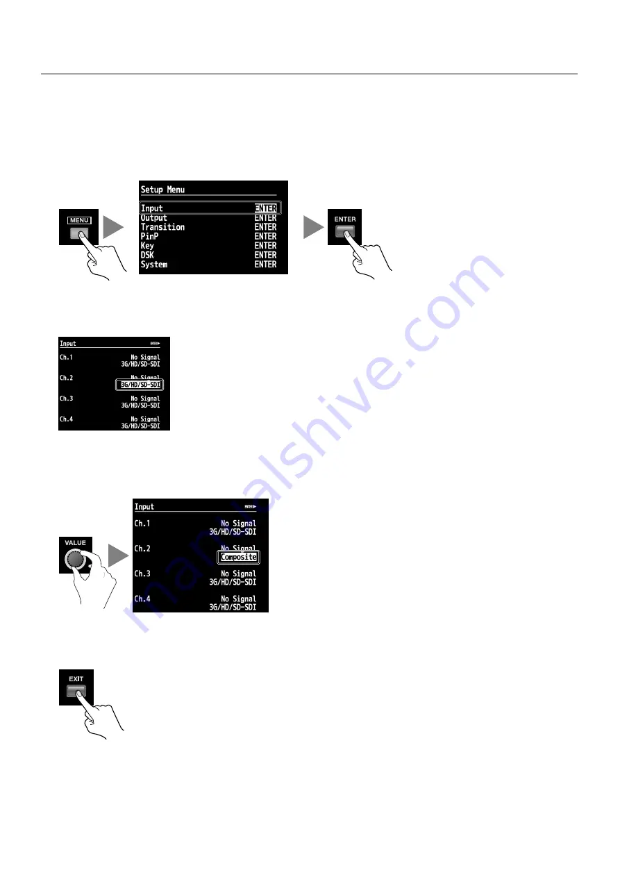
Connecting source equipment to a COMPOSITE IN connector requires changing the setting on the V-800HD. Use the procedure 
described below to change the source from SDI to composite.

1.

Display the Input menu.

Press the [MENU] button to display the menu. Use the [CURSOR] buttons to select [Input], then press the [ENTER] button to 
display the Input menu.

fig.open-input-menu.eps

2.

Select the channel.

Use the [CURSOR] buttons to select which input format you wish to use at this input channel.

fig.select-channel.eps

3.

Change the assignment.

Turn the [VALUE] dial to change the setting to [Composite] or [3G/HD/SD-SDI], depending on which source type is plugged into 
that input.

fig.change-assign.eps

4.

Exit the menu.

Press the [EXIT] button several times to quit the menu.

fig.close-menu.eps

スクリーンショット 

Summary of Contents for V-800HD MKII

Page 1: ...e provided by your new unit owner s manual should be read in its entirety The manual should be saved and kept on hand as a convenient reference Copyright 2012 ROLAND CORPORATION All rights reserved No part of this publication may be reproduced in any form without the written permission of ROLAND CORPORATION Roland is either registered trademark or trademark of Roland Corporation in the United Stat...

Page 2: ...ovided plug does not fit into your outlet consult an electrician for replacement of the obsolete outlet WARNING IMPORTANT As the colours of the wires in the mains lead of this apparatus may not correspond with the coloured markings identifying the terminals in your plug proceed as follows The wire which is coloured GREEN AND YELLOW must be connected to the terminal in the plug which is marked by t...

Page 3: ...the unit and keep it from wobbling 008e Use only the included power cord Use only the attached power supply cord Also the supplied power cord must not be used with any other device 008f Connect the power cord to an outlet of the correct voltage The unit should be connected to a power supply only of the type described in the operating instructions or as marked on the side panel of unit 009 Do not b...

Page 4: ...ower plug from the power outlet whenever the unit is to remain unused for an extended period of time Any accumu lation of dust between the power plug and the power outlet can result in poor insulation and lead to fire 104 Manage cables for safety Try to prevent cords and cables from becoming entangled Also all cords and cables should be placed so they are out of the reach of children 106 Avoid cli...

Page 5: ...kind to avoid the possibility of discoloration and or deformation Additional Precautions poke mon This unit allows you to switch images or turn video effects on off at high speed For some people viewing such images can cause headache nausea or other discomfort Do not use this unit to create video that might cause these types of health problems Roland Corpo ration will accept no responsibility for ...

Page 6: ...nnecting Output Equipment 25 Connecting a Projector 25 Connecting Recording Equipment 25 Tally Output 25 Selecting the Output Format 26 Inputting HDCP Signals 29 Basic Operations 31 Using Buttons to Switch the Video 31 Using the Fader to Switch the Video 33 Applying Fade to Final Output 34 Compositing the Video 35 Compositing Using Picture in Picture 35 Compositing Using Luminance Chroma Key 37 Co...

Page 7: ...ions 51 Appendices 52 Main Specifications 52 Name Plate 52 About Remote Control 53 About Rack Mounting 53 About the Input Template 53 Troubleshooting 54 Dimensions 55 V 800HD Version 1 50 Added Functions 56 Index 60 ...

Page 8: ...ations that depict what should typically be shown by the display Note however that your unit may incorporate a newer enhanced version of the system so what you actually see in the display may not always match what appears in the manual MMP Moore Microprocessor Portfolio refers to a patent portfolio concerned with microprocessor architecture which was developed by Technology Properties Limited TPL ...

Page 9: ...like fig RGB out eps Once you select the setup is kept and valid from the next booting While booting 1 or 2 of the MEMORY will light up in red and enables you to check your setup Pressing the MENU button on the top panel displays the menu To make the menu disappear press the EXIT or MENU button on the top panel fig menu display eps For information on using the menus refer to Menu Operations p 51 F...

Page 10: ...is sent to the final output PGM A green border is displayed around channel that is on standby PVW The input source images are displayed here directly without any parameter changes Settings such as color adjustment or scaling are not applied Changing the channel assignments at the cross point p 49 also changes the order of displayed sources Still images imported from USB memory are not displayed on...

Page 11: ...ectrical charge which is absolutely harmless However if you are concerned about this connect the ground terminal see figure with an external ground When the unit is grounded a slight hum may occur depending on the particulars of your installation If you are unsure of the connection method contact the nearest Roland Service Center or an authorized Roland distributor as listed on the Information she...

Page 12: ...ent power loss due to the plug being pulled out if the power cord is accidentally yanked 1 Connect the power cord to the AC IN connector fig connect AC eps 2 Secure the power cord in place with the cord hook Clamp the cord hook onto the power cord to secure it in place fig hook cord eps About the Cord Hook ...

Page 13: ...er to the V 800HD fig power on eps 3 Turn on the power to the source devices Turn on the power to the source devices like video cameras connected to the V 800HD 4 Turn on the power to the output devices Turn on the power to the output devices like projectors connected to the V 800HD Turning the Power Off 1 Turn off the power to the output devices Turn off the power to the output devices connected ...

Page 14: ...ts They light up when valid signals are input 6 Cross Points 10 buttons each on the PGM and PST EFFECT sides Use these to select the output video and standby video PGM The button for the channel currently being output lights up in red and the channel is displayed in PGM section of the multi view monitor PST EFFECT These select the video you want to output put into standby next and the source for c...

Page 15: ...e http www rolandsystemsgroup net By default the video fades to black You can use the menus to change it It is possible to fade to an imported still image p 46 or to the still image freeze frame made from the video currently being output p 48 10 TRANSITION Dial and Indicator Use this dial to set the transition time p 31 You can use the menus to change time unit to be displayed here By default the ...

Page 16: ...put use the menus to change the source Refer to Making a Composite Connection p 20 6 DVI I HDMI IN Connectors Connect a computer or other source equipment capable of DVI output DVI input is assigned to channels 5 through 8 Use the switches to select DVI A or DVI D as required to match the type of output signal from the source equipment Refer to Making a DVI HDMI Connection p 22 7 RGB COMPONENT IN ...

Page 17: ...tor Connect a multi view monitor here p 9 14 DVI D HDMI OUT Connectors Connect a projector or other output equipment capable of DVI D input By using a conversion cable from DVI D to HDMI you can also connect equipment capable of HDMI input 15 SDI OUT Connectors Connect a TV monitor a video deck or other equipment capable of SDI input When the setting for HDCP signal input has been made nothing is ...

Page 18: ...ackground Fade to Still Image Output Freeze SD OUT Scaler Selector SDI OUT 1 DVI D HDMI OUT 1 Mixer Input Mixer Output DSK Source DSK Output Video Mixer PinP Key Composite SDI DVI I HDMI RGB Component Composite SDI HDMI OUT Back ground Frame Sync Scaler Color Correct Color Correct Cross Point 1 Ext Key 2 4 1 2 3 4 Output Capture PVW PGM AUX Color Correct Color Correct Color Correct Color Correct S...

Page 19: ...9 94p 1080 50i 1080 59 94i 1080 50p 1080 59 94p Component 480 59 94i 576 50i 480 59 94p 576 50p 720 59 94p 720 50p 1080 59 94i 1080 50i 1080 59 94p 1080 50p RGB 640x480 60 Hz 800x600 60 Hz 1024x768 60 Hz 1280x768 60 Hz 1280x1024 60 Hz 1366x768 60 Hz 1400x1050 60 Hz 1600x1200 60 Hz 1920x1200 60 Hz Reduced Blanking DVI HDMI 640x480 60 Hz 800x600 60 Hz 1024x768 60 Hz 1280x768 60 Hz 1280x1024 60 Hz 13...

Page 20: ...e equipment to the SDI IN connectors If a signal is input that has an aspect ratio different form the V 800HD s output format the image fills the screen at the output default setting You can also use the menus p 51 to select Letterbox Crop or Squeeze Making Composite Connections Connect equipment capable of composite output such as video cameras or DVD players to the COMPOSITE IN connectors When c...

Page 21: ... to select Input then press the ENTER button to display the Input menu fig open input menu eps 2 Select the channel Use the CURSOR buttons to select which input format you wish to use at this input channel fig select channel eps 3 Change the assignment Turn the VALUE dial to change the setting to Composite or 3G HD SD SDI depending on which source type is plugged into that input fig change assign ...

Page 22: ...signal from the computer If this switch is set incorrectly you will not have any input signal When DVI A has been selected analog RGB can also be connected In such cases use a conversion cable from mini D Sub 15 pins to DVI fig DVI selection eps Making an RGB Component Connection Connect computers capable of analog RGB output to the RGB COMPONENT IN connectors By using a conversion cable from comp...

Page 23: ...ut then press the ENTER button to display the Input menu fig open input menu eps 2 Select the channel Use the CURSOR buttons to select which input format you wish to use at this input channel If the target channel is not displayed press the left or right CURSOR button to change the page fig select channel RGB eps 3 Change the assignment Turn the VALUE dial to change the setting to RGB Component fi...

Page 24: ...ut eps You can connect a source device for synchronizing You can send thru out the synchronizing signal from the THRU connector fig connect clock source eps The V 800HD supports the external clocks shown below To synchronize with an external clock select Reference in System menu and set the value to External Black burst frame synchronization Bi level synchronization tri level synchronization The c...

Page 25: ...necting a video monitor capable of tally input to these makes it possible to illuminate the tally lamps on the monitor The lamp is switched on and off according to the channel selection enabling you to see which channel is currently in use on the monitor The specifications of TALLY connectors are as below D sub 15 pin type max input 12 V 200 mA Open collector type The channels shown below are assi...

Page 26: ...be output from digital and analog connectors fig output flow eps The OUTPUT FORMAT indicator for the format selected for the main output lights up The corresponding output formats of the SD HD and RGB indicators are as follows SD 480i 576i HD 480p 576p 720p 1080i 1080p RGB VGA 640x480 through WUXGA 1920x1200 By default HD is selected and the unit is set to output 1080i fig format indicator eps For...

Page 27: ...put menu Press the MENU button to display the menu Use the CURSOR buttons to select Output then press the ENTER button to display the Output menu fig open output menu eps 2 Select the main output Use the CURSOR buttons to go to Format and select the Main format display area then use the VALUE dial to change the format fig change format eps 3 Exit the menu Press the EXIT button several times to qui...

Page 28: ... SDI OUT Connectors 480 59 94i 576 50i 720 50p 720 59 94p 1080 50i 1080 59 94i 1080 50p 1080 59 94p RGB COMPONENT OUT Connectors 640x480 800x600 1024x768 1280x768 1280x1024 1366x768 1400x1050 1600x1200 1920x1200 480 59 94p 576 50p 720 59 94p 720 50p 1080 59 94p 1080 50p For switching of 59 94p and 50p go to the System menu and use Frame Rate to select 59 94Hz or 50Hz DVI D HDMI OUT Connectors 640x...

Page 29: ... display the System menu fig open system menu eps 2 Change the setting Use the CURSOR buttons to select HDCP Turn the VALUE dial to change the setting from OFF to ON A confirmation screen appears Press the ENTER button fig HDCP setting eps 3 Exit the menu Press the EXIT button several times to quit the menu fig close menu eps When the setting change just described has been made output from the SD ...

Page 30: ... or when the connected device is not compatible with HDCP It goes dark when HDCP is set to OFF About Verification of HDCP compatible Equipment You can examine the HDCP compatibility of source equipment and output equipment From the Input menu or Output menu selecting HDCP displays a screen like the one shown below If the target channel is not displayed press the left or right CURSOR button to chan...

Page 31: ...n time is set at 1 second When the unit is started for the first time the indicator displays 1 0 You can also use the menus p 51 to select the unit of time display You can select from seconds frames or seconds frames as the display mode fig time dial eps 3 Select the transition effect Use the buttons in the WIPE PATTERN section to choose a transition effect fig wipe pattern eps MIX The transition ...

Page 32: ...video and press the AUTO button when you want to make the transition The picture changes and the PGM button for the selected channel lights up in red On the multi view monitor a red border is displayed around the channel being output The output video is also displayed in the PGM section The channel selected before transition on the PGM side becomes the selected one on the PST EFFECT side The butto...

Page 33: ... the multi view monitor the selected channel is displayed with a green border around it The video on the selected channel is also displayed in the PVW section 4 Switch the video Move the video fader in the opposite direction of step 1 The button of the channel on PGM side lights up in red On the multi view monitor a red border is displayed around the channel being output The output video is also d...

Page 34: ...seconds Fade color The default setting is black Fades to Other Images Fades to plain color like black are possible Using menus you can change settings Fade to Still Image You can apply a fade to a still image imported into the V 800HD s internal memory from a USB memory device p 44 From the System menu select Output Fade then for the Mode setting select Fade to Still Image If the still image is as...

Page 35: ... three layer compositing You can switch or composite the background video while continuing to display the logo or text unchanged Use the LEVEL dial to adjust the amount of keying By default video input on channel 8 is assigned as the source for the DSK You can select a different channel using the menus p 51 Even if you switch video while compositing is carried out no glitch occurs to the output vi...

Page 36: ...djust the size and positioning You can use the menus to save the size and position as well as settings for border color width and other parameters to individual PinP position buttons You can also zoom the picture in the inset screen fig adjust size position eps 5 Output the composited result Use the AUTO or CUT button or the video fader to output the result of compositing The color of the PinP pos...

Page 37: ...s 2 Select the channel to overlay Use buttons 1 through 8 on the PST EFFECT side to select the channel to overlay fig select foreground eps 3 Preview the results of compositing At the KEY section press the ON button to make it light up green When the ON button lights up a preview of the compositing result is displayed in PVW section of the multi view monitor At this stage the final output has not ...

Page 38: ...also makes the overlaid picture disappear Combining Picture in Picture and luminance chroma key lets you use the SIZE dial to enlarge or reduce the size of the overlaid picture You can also use the POSITION joystick to move the display position When combining press any of the PinP buttons to make it light up fig key PinP sample eps About External Key At the Key menu selecting Mode and changing the...

Page 39: ...At the DSK section press the PVW button to make it light up The video overlaid with the logo or text from source channel by default channel 8 is displayed in PVW section of the multi view monitor At this stage the final output has not yet been changed fig DSK PVW eps 3 Adjust the amount of keying and the degree of edge blur While viewing the preview use the LEVEL dial in the DSK section to adjust ...

Page 40: ...background picture while continuing to display a logo or text unchanged Use the buttons on the PST EFFECT side to select the standby video then use the AUTO or CUT button or the video fader to change the background picture When you are using external key DSK cannot be used When using DSK be sure to set Key Mode to Self Key The settings of a compositing operation for a DSK source will be remembered...

Page 41: ...g scale PVW eps 3 Output the enlarged or reduced picture Use the AUTO or CUT button or the video fader to output the picture on standby You can also enlarge or reduce the picture and adjust its display position by changing the values of Zoom and Position in the Input menu In the Input menu you can also change cropping parameters and the aspect ratio for the picture Enlarging Reducing the Currently...

Page 42: ... CH 8 use the CURSOR buttons to select the channel whose text string you want to change Pressing the ENTER button switches the display to the screen for changing the text string You can also hide the labels by going to the Multi View Label list and setting Indicate to OFF fig select label channel eps 3 Change the text string Use the CURSOR buttons to move the cursor left or right and turn the VALU...

Page 43: ...selected bank lights up Choose a bank from 1 to 8 to select the destination for saving fig press bank eps 4 Select the number to save to Press a button from 1 to 8 to select the destination for saving Settings are saved at the selected number in the selected bank fig select button eps Recalling Saved Settings When the V 800HD starts memory 1 in bank 1 is loaded You can call up the settings saved a...

Page 44: ...pe of the USB memory device correct operation may not be possible Follow the procedure below to format the connected USB memory device You must format your USB memory device in the V 800HD or it will not be recognized by the unit 1 Display the System menu Press the MENU button to display the menu Use the CURSOR buttons to select System then press the ENTER button to display the System menu fig ope...

Page 45: ...ge the text string The extension of the file name is V08 If you have edited the file name on your computer small letters are displayed after conversion to capitals fig file name edit eps 5 Save to the USB memory device Press the ENTER button to finalize the file name Pressing it displays the message Push ENTER to execute To save press the ENTER button 6 Exit the menu Press the EXIT button several ...

Page 46: ...e must be as below Data in other formats or sizes cannot be imported into the V 800HD Format Bitmap bmp 24 bits pixel uncompressed Maximum resolution 1920 x 1200 Assigning Still Images to Channels 9 10 Still images saved on a USB memory device can be assigned to channel 9 or channel 10 on the V 800HD 1 Save still image data on a USB memory device Save the still image data in the root directory of ...

Page 47: ...e more copies the selected still image file from the USB memory device to the V 800HD s internal memory 7 Select the channel for assignment Return temporarily to the initial menu screen and select the Input menu Press the CURSOR buttons to select CH 9 or CH 10 If the target channel is not displayed press the left or right CURSOR button to change the page 8 Choose the still image to assign to the s...

Page 48: ...u can select from among PGM PVW or AUX Selecting a source makes the video appear at PGM section of the multi view monitor 4 Select the memory of the destination for saving Under Destination select saving destination memory number 1 through 16 in Still Image Memory No fig destination memory eps 5 Execute creation and saving of the still image Use the CURSOR buttons to highlight Execute then press t...

Page 49: ... the System menu 2 Display the cross point setting screen Select Cross point Assign then press the ENTER button The channel assignments for the respective cross points are displayed 3 Change the assignments Use the CURSOR buttons to select a cross point 1 to 10 then turn the VALUE dial to change the channel assignment fig cross point menu eps 4 Exit the menu Press the EXIT button several times to ...

Page 50: ...t 1 Display the System menu Press the MENU button to display the menu Use the CURSOR buttons to select System then press the ENTER button to display the System menu 2 Select the Factory Reset menu Use the CURSOR buttons to select Factory Reset then press the ENTER button The message Push ENTER to execute appears If the target menu is not displayed press the left or right CURSOR button to change th...

Page 51: ...hange the page shown Also when ENTER is displayed at the top of the screen you can move down one level by pressing the ENTER button fig select item eps 4 Change the setting value If the displayed setting value is highlighted you can change the value by turning the VALUE dial You can change a setting value up or down by 10 units at one time by holding down the ENTER button and turning the VALUE dia...

Page 52: ...00 60 Hz Reduced Blanking Conforms to VESA DMT Version 1 0 Revision 10 Windows R Bitmap File bmp Maximum 1920 x 1200 pixels 24 bit per pixel uncompressed Still Image Input Output Level and Impedance Analog HD RGB 1 0 Vp p 75 ohms 0 7 Vp p 75 ohms H V 5 VTTL Composite Analog Video Composite BNC type x 4 Select Composite or SDI using menu per channel Component HD DB 15 type x 4 Combined use with Ana...

Page 53: ...ause malfunction When installing the rack mount angles turn off the power to the V 800HD and detach the power cord and all connection cables Also be sure to install using the original screws Mounting in a 19 inch Rack When mounting the unit in a rack observe the following precautions The video fader protrudes beyond the mounting surface of the rack Take care not to damage it when mounting the unit...

Page 54: ...ll image assigned to channel 10 A still image cannot be assigned to channel 10 and output fade at the same time When assigning a still image to an output fade change the channel 10 assignment to a color background Compositing with DSK is not possible Is External Key p 38 on When using DSK set this to off Select M ode in Key menu and turn it to Self key A USB memory device cannot be used Has the US...

Page 55: ...55 Appendices fig dimensions eps Dimensions 465 482 436 445 1 76 2 57 1 57 1 37 5 274 6 5 26 5 4 115 9 Unit mm ...

Page 56: ...ble A B Mode Switching You can select A B mode for video switching PGM PST is the default mode Regardless to the PGM section or PST EFFECT section of cross points PGM is determined by the video fader position The indicator of the PGM output channel lights in red The indicator of the PST output channel lights in green While you are compositing images the indicator of background channel lights in re...

Page 57: ...d Expanded Color Correction Range The range of color correction is expanded Fine Adjustment of Chroma Key HUE The extraction color was fixed to blue or green in previous version Now it s possible to fine adjust the color Width is same as Hue adjustment of previous version Menu Items Setting Value Output AUX Source Mixer Input Mixer Output DSK Source DSK Output Input CH 1 Input CH 10 Menu Items Set...

Page 58: ...oduct However of HDCP of the V 800HD is turned on the multi view screen is filled with plain blue It can display the menu screen only Version Number Display You can check the version number in System menu of the V 800HD The memory saved settings is not compatible with the previous version At the first booting after update factory reset is executed automatically ...

Page 59: ...59 ...

Page 60: ...H HDCP 29 HDMI 19 22 I INPUT STATUS 14 L Labels 42 luminance key 37 M Main Output 27 MEMORY 15 43 Menu 51 menu 10 MIDI 16 Multi view Monitor 9 O OUTPUT FADE 15 34 P PGM Section 9 Picture in Picture 35 PVW Section 9 R REFERENCE 17 RGB 22 RS 232C 16 S Scaling 14 SDI 19 20 Setup 14 Sharing 24 Source Monitors 9 Still image 46 T TALLY 16 Tally 25 TRANSITION 15 Transition Effects 31 U USB 14 44 V Video ...

Page 61: ...ed and used in accordance with the instruction manual may cause harmful interference to radio communications Operation of this equipment in a residential area is likely to cause harmful interference in which case the user will be required to correct the interference at his own expense This device complies with Part 15 of the FCC Rules Operation is subject to the following two conditions 1 this dev...

Page 62: ...etic environments E1 residential E2 commercial and light industrial E3 urban outdoors E4 controlled EMC environment ex recording studio broadcasting studio which are specified in EN55103 1 and EN55103 2 GR SK CZ SI LV LT EE PL HU FI SE NO DK NL PT ES IT DE FR UK For EU Countries ...

Page 63: ......

Page 64: ... 5 1 0 0 0 2 9 1 0 1 0 3 ...

Reviews: