background image

41

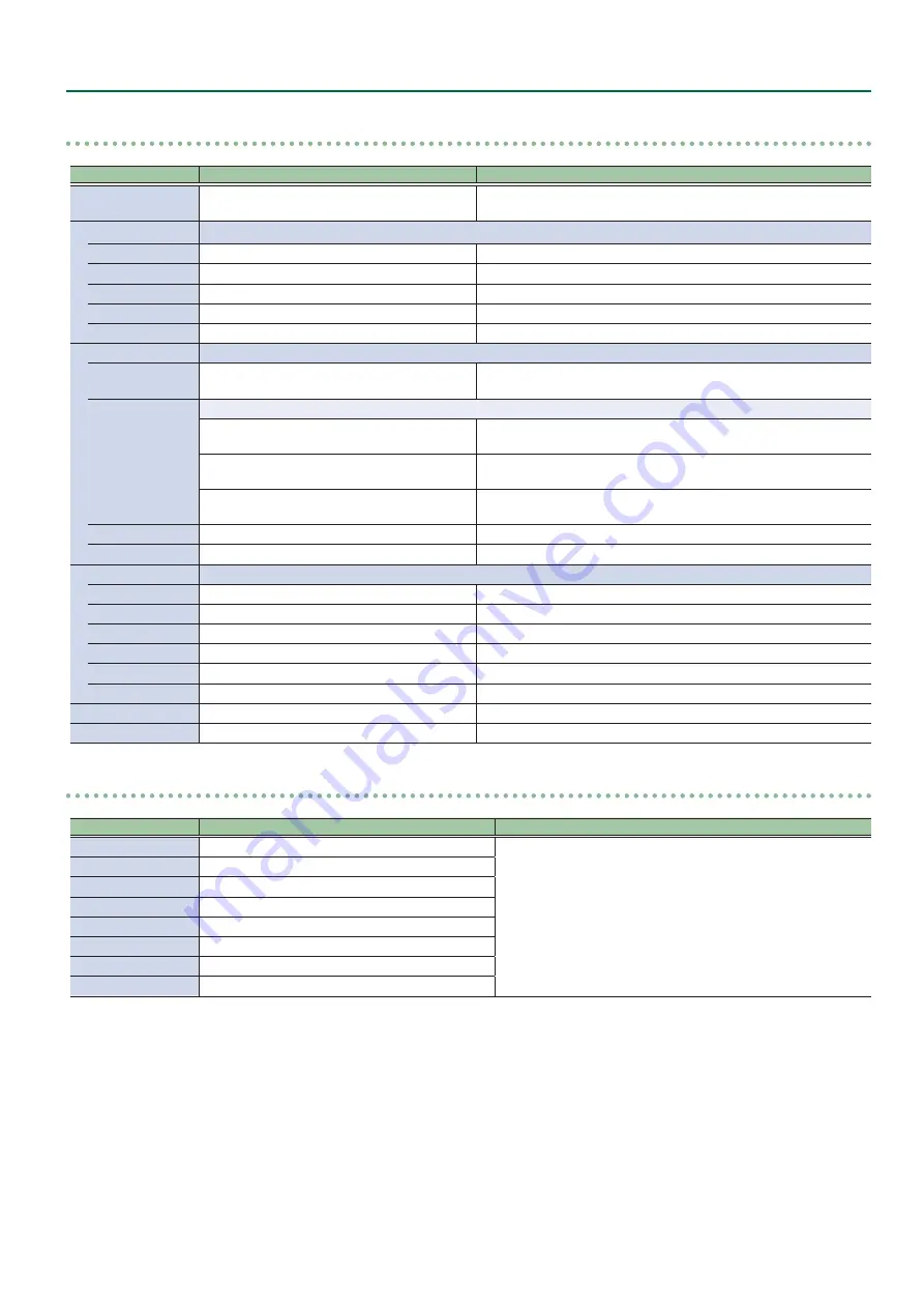
Menu List

Processing

0

[VALUE]

Menu item

Value 

(Bold: default)

Explanation

Format

1080p, 

2160p(UHD)

, 2160p(DCI), 1920x1080, 

3840x2160, 4096x2160

This part select V-600UHD’s output (system) format.

Scaling

You use the following items to make settings for scaling.

Zoom

10–

100

–1000%

This adjusts the zoom ratio.

Correction H

-4000–

0

–+4000

This adjusts the horizontal zoom size.

 V

-4000–

0

–+4000

This adjusts the vertical zoom size.

Position H

-4096–

0

–+4096

This adjusts the display position in the horizontal direction.

 V

-2160–

0

–+2160

This adjusts the display position in the vertical direction.

Cropping

You use the following items to make settings for cropping.

Orientation

Upper Left

, Upper Right, Lower Left, Lower 

Right, Center

This sets the orientation of cropping.

Type

This sets the orientation of cropping.

Full

When the “Zoom” value is “100%,” the entirety of the image is shown 

on the output screen.

4:3, 5:4, 16:9

 The image will be cropped according to the selected aspect ratio. If 

the Zoom value is 100%, the image will be letterboxed.

Manual

The image will be cropped according to the “Manual Width” and 

“Manual Height” settings.

Manual Width

0–

512

–4096

This adjusts the horizontal size.

Manual Height

0–

512

–2160

This adjusts the vertical size.

Color Correction

You use the following items to perform color correction.

Brightness

-64–

0

–+63

This adjusts the brightness.

Contrast

-64–

0

–+63

This adjusts the contrast.

Saturation

-64–

0

–+63

This adjusts the color saturation.

Red

-64–

0

–+63

This adjusts the red level.

Green

-64–

0

–+63

This adjusts the green level.

Blue

-64–

0

–+63

This adjusts the blue level.

Color Gamut

Rec.709

, Rec.2020

This part select output (system) color gamut.

Dynamic Range

SDR

, HDR PQ, HDR HLG

This part select output (system) dynamic range.

Cross-point Assign

0

[VALUE]

Menu item

Value 

(Bold: default)

Explanation

XPT1

Ch.1

–8, None

This sets the input channel to be assigned to Cross-point [1]–[8] 

buttons.

XPT2

Ch.1–

2

–8, None

XPT3

Ch.1–

3

–8, None

XPT4

Ch.1–

4

–8, None

XPT5

Ch.1–

5

–8, None

XPT6

Ch.1–

6

–8, None

XPT7

Ch.1–

7

–8, None

XPT8

Ch.1–

8

, None

Summary of Contents for V-600UHD

Page 1: ... Using Imported Still Images 15 Applying a Fade to the Final Output Video Output Fade 16 Video Composition Operations 17 Compositing Using Picture in Picture PinP 17 Compositing Using Luminance Key Chroma Key 18 Audio Operations 20 Adjusting the Input Output Volume 20 Muting the Input Output Audio 20 Matching the Timing of the Input Output Audio with the Video 20 Interlinking Audio Output to Video...

Page 2: ...off unlit Recalls settings that are saved in memory BANK button When this is turned on lit the 1 8 buttons function as bank selection buttons for memories STORE button When this is turned on lit you can save settings in memories Name Explanation 6 PinP ROI SCALING POSITION stick Adjusts the display position of the input video or PinP inset screen SIZE knob Enlarges or reduces the size of the input...

Page 3: ...own you can hold down the MENU button and press a PST cross point 1 8 button to successively switch the input source setting Name Explanation 12 MODE AUX COMPOSITION button DSK button 2 Selects the destination of the video The video selected by the AUX COMPOSITION DSK cross point 1 8 button is sent AUX COMPOSITION button Lit red AUX Lit yellow COMPOSITION DSK button Lit blue DSK 13 WIPE PATTERN 1 ...

Page 4: ... the RGB IN 1 connector or the HDMI IN 1 connector AUDIO OUT L R connector Output the results of audio mixing Connect an audio recorder amplifier speakers or other such equipment Analog RGB output connector HDMI output connector SDI output connector HDMI OUT 1 3 connectors SDI OUT connector Outputs the video audio signals Connect projectors recording equipment and external displays HDMI input conn...

Page 5: ...y Front panel RS 232 connector LAN connector Cord hook Clamps the power cord to secure it in place POWER switch Turns the power on off Ground terminal Connect this to an external earth or ground if necessary TALLY GPI connector Connect devices provided with a tally light feature or with control signal output functionality to this connector For details on the specifications of the TALLY GPI connect...

Page 6: ... video to be output next 2 PGM program section This displays the final output video 3 CH 1 8 section This monitors the video input via channels 1 8 A red border is displayed around the final video output A green border is displayed around the preset video the video to be output next Settings for scaling p 11 is not applied Changing the channel assignments at the cross point p 24 also changes the o...

Page 7: ... not be saved properly 5 5 If you need to turn off the power completely first turn off the V 600UHD then unplug the power cord from the power outlet Using the Menus This explains how to display menus and make settings for video and for the V 600UHD itself Menus are shown only on the multi view monitor connected to the MULTI VIEW connector p 6 1 Press the MENU button to display the menu The MENU bu...

Page 8: ...EA 861 F 1920 x 1080 60 Hz FHD SDI IN Video SMPTE ST274 1080 59 94i 1080 50i 1080 59 94p 1080 50p SMPTE ST2036 2160 59 94p UHD 4K 2160 50p UHD 4K SMPTE ST2048 2160 59 94p DCI 4K 2160 50p DCI 4K Output Formats Output connector Supported formats Output format Flame rate Video When set at 59 94 Hz Video When set at 50 Hz When set at PC format HDMI OUT CEA 861 F 1080 59 94p 1080 50p 1920 x 1080 60 Hz ...

Page 9: ...ALUE knob to specify the video source to assign to the channel HDMI RGB IN1 Value Explanation HDMI IN1 This inputs video via an HDMI IN1 connector RGB IN1 This inputs video via an RGB IN1 connector PG STILL2 Value Explanation PG This assigns a pattern generator STILL2 This assigns a still2 image 3 Press the MENU button to quit the menu Sharing aVideo Source You can share separate video sources amo...

Page 10: ... to select PGM PVW or AUX and set the assigned bus Menu item Signal Bus setting HDMI OUT 1 PGM PVW AUX HDMI OUT 2 PGM PVW AUX HDMI OUT 3 PGM PVW AUX SDI OUT PGM fixed MULTI VIEW No bus selection 3 Press the MENU button to quit the menu Adjusting Final OutputVideo You adjust the final video output to match the equipment receiving output from the V 600UHD 1 Select the MENU button System Processing a...

Page 11: ...ess PST cross point buttons 1 8 to select the video that you want to control 3 Use the POSITION stick to adjust the display position of the video Also use the SIZE knob to enlarge or reduce the video The operation results are applied in the PVW section of the multi view monitor The video in the CH 1 8 section of the multi view monitor is not updated In the section that is specified as Shared Input...

Page 12: ...e Explanation On Copyright protected HDCP video can be input HDCP is also added to the video that is output Off Copyright protected HDCP video cannot be input 3 Press the MENU button to quit the menu Checking HDCP compatible equipment When HDCP is set to On you can use the MENU button Signal Status Input Ch 1 8 HDCP the Input menu to check the status of HDCP compatibility of source equipment Outpu...

Page 13: ...ference clock SDI IN5 A signal input via an SDI IN5 connector is used as the reference clock When set to SD IN5 adjust the following System menu items as needed Value Explanation Clock Adjust This adjusts the phase horizontally Adjust this when output is horizontally out of sync with the operation of other devices using the same clock Line Adjust This adjusts the phase vertically Adjust this when ...

Page 14: ...view monitor 4 Move the video fader in the direction opposite to the direction in step 1 The output video is switched When the video has been switched completely the lighted buttons for the PGM position and PST position change places MEMO Directly selecting the video channel at the PGM position of the video currently being output switches the video with a cut regardless of any selection of a trans...

Page 15: ...t the still image file you want to import 5 Select Load and press the ENTER button The message Are you sure appears If you want to cancel the operation select NO and press the VALUE knob 6 Select YES and press the VALUE knob The still image is imported into the unit 7 Press the MENU button to quit the menu Assigning a Still Image to Channel 7 or 8 This takes a still image imported from a USB flash...

Page 16: ...o output 1 Select the MENU button System Output Fade and press the VALUE knob 2 Select a menu item then use the VALUE knob to make the detailed settings Details on menu items see p 40 3 Press the MENU button to quit the menu MakingtheFinalVideoOutputFadeOut FadeIn During the fade the OUTPUT FADE button flashes 1 Press the OUTPUT FADE button to perform a fade out When the fade out is complete the O...

Page 17: ...nal output has not yet been changed 5 Press the PinP ROI SCALING PinP1 or PinP2 button to select the object of control 6 Use the POSITION stick and the SIZE knob to adjust the position and size of the inset screen 7 If the object of control is PinP1 press the COMPOSITION button if PinP2 press the DSK button At this time the PinP 1 or 2 button light up in red Pressing the COMPOSITION or DSK button ...

Page 18: ... Green This uses a color threshold to make green transparent Chroma Manual This uses a color threshold to make manual color transparent 3 Press the MENU button to quit the menu Compositing using key 1 Press a cross point 1 8 button in the PGM section to select the video you want to make the inset screen 2 Press the MODE AUX COMPOSITION button or DSK button to select the send destination for the vi...

Page 19: ...O or CUT button a second time makes the overlaid video disappear MEMO 5 5 When you combine PinP p 17 with the compositing results from luminance or chroma key the superimposed video becomes the inset screen You can also use the POSITION stick and the SIZE knob to adjust the display position and size of the overlaid video Making advanced settings for chroma key When the key type is Chroma Manual yo...

Page 20: ...on to quit the menu Interlinking Audio Output toVideo Switching Audio Follow You can associate audio with a video switch so that when the video is switched the specified audio alone is output automatically and other audio is automatically muted 1 Use MENU button Audio Input to select the object for audio follow and press the VALUE knob 2 Select Follow and use the VALUE knob to turn the setting On ...

Page 21: ...t HDMI IN 1 4 or AUDIO IN and press the VALUE knob 2 Select Aux Send and use the VALUE knob to specify the volume that is sent to the aux bus 3 Press the MENU button to quit the menu Selecting the audio source that is output For each output connector you can select either a specified channel of the MAIN bus or the AUX bus as the source that will be output For SDI OUT audio you can select either th...

Page 22: ...t settings are saved current memory has not been edited Unlit Memory in which no settings are saved The STORE button blinks the current settings are saved and then the STORE button goes dark MEMO If you don t want to change the save destination bank steps 2 3 are not required Recalling a memory 1 Press the BANK button button lit then press the MEMORY button for the bank number whose settings you w...

Page 23: ...m select the USB Memory Parameter Load and press the VALUE knob 2 Select the file that you want to recall select Load and press the VALUE knob The message Are you sure appears If you want to cancel the operation select NO and press the VALUE knob 3 Select YES and press the VALUE knob The settings are recalled and the values in the unit s memories are overwritten 4 Press the MENU button to quit the...

Page 24: ...LUE knob Formatting of the USB flash drive is carried out 3 Press the MENU button to quit the menu Changing Cross point Assignments You can change the channels assigned to the cross point 1 8 buttons You can also disable operation of a cross point button by assigning no channel to the button 1 Select the MENU button System Cross point Assign and press the VALUE knob 2 Select cross point cross poin...

Page 25: ...tion setup Composition This is for Picture in Picture setup luminance and chroma key setup DSK This is for Picture in Picture setup luminance and chroma key setup Audio This is for audio setup USER This is for setup of user function System This is for system setup of the V 600UHD MEMO 5 5 When a setting value has menu items that let you make more detailed settings ENTER is displayed at the top of ...

Page 26: ...UE knob displays the detailed information RESOLUTION Video Format 1080pRATE 2160p UHD RATE 2160p DCI RATE PC Format WxH RATE RATE is displayed only in integer part example 59 94 0 59 Input Ch 1 Ch 80 VALUE Menu item Displayed value Explanation Source Input Ch 1 HDMI IN1 RGB IN1 Shared Ch 1 8 This part displays the video source to assign to the channel Input Ch 2 4 HDMI IN2 4 Shared Ch 1 8 Input Ch...

Page 27: ...HD 2160p DCI 50 59 94 60 HDCP Off On Color Gamut Rec 709 Rec 2020 RGB Full RGB Limited Dynamic Range SDR HDR PQ HDR HLG 9 9 HDMI1 This part displays output bus settings and down convert settings BUS PGM PVW AUX Down Convert Disabled Enabled 9 9 HDMI2 BUS PGM PVW AUX Down Convert Disabled Enabled 9 9 HDMI3 BUS PGM PVW AUX Down Convert Disabled Enabled 9 9 SDI BUS PGM Down Convert Disabled Enabled ...

Page 28: ...m 10 100 1000 This adjusts the zoom ratio Center Position H 4096 0 4096 This adjusts the display position in the horizontal direction V 2160 0 2160 This adjusts the display position in the vertical direction Type This sets the scaling type Full The input image will be displayed fully on output screen The aspect ratio will be changed Letterbox The entirety of the input image will be displayed on ou...

Page 29: ... Ch 1 6 RGB Full RGB Limited This part select color gamut or color spaces of Input Ch 7 8 Dynamic Range Type SDR HDR PQ HDR HLG Auto This part select dynamic range of Input Ch 1 6 Input Ch 7 Ch 8 are fixed at SDR Correction 64 0 63 This adjust dynamic range Sampling You use the following items for make settings for sampling Available when Source is set to RGB IN1 Auto Sampling Execute This execute...

Page 30: ...ase of video resolution and fixed at Disabled in the case of PC resolution Down Convert Disabled Enabled This specifies whether down convert from 4K to FHD is enabled or disabled Available when Output Format is set to 2160p UHD 3G SDI Mapping Level A This displays the mapping structure for 3G SDI output MULTI VIEW0 VALUE Menu item Value Bold default Explanation Layout Upper Left Upper Right Lower ...

Page 31: ...ve for video transition Position H 2 100 0 0 100 0 This sets the horizontal position of start video transition V 3 100 0 0 100 0 This sets the vertical position of start video transition Aspect ratio 4 1 1 4 3 3 2 16 9 This sets aspect ratio of video transition Correction H 2 100 0 0 100 0 This adjusts the horizontal position of start video transition V 3 100 0 0 100 0 This adjusts the vertical po...

Page 32: ...160 0 2159 This adjusts the display position in the vertical direction Window Use the following items to make the settings for the inset screen Size 10 0 30 0 100 0 This adjusts the zoom ratio Aspect ratio 1 1 4 3 16 9 System This sets the aspect ratio of the inset screen Corrction H 100 0 0 100 0 This adjust the horizontal size of the inset screen V 100 0 0 100 0 This adjust the vertical size of ...

Page 33: ...s uses a color threshold to make manual color transparent Level 0 32 255 This adjusts the amount of extraction Gain 0 255 This adjusts the amount of edge blur Chroma Manual Available when Type is set to Chroma Manual Hue Center 0 120 359deg This adjusts the center position for hue of key color Width 0 10 359deg This adjusts the hue width range of key color Saturation Center 0 90 100 This adjusts t...

Page 34: ... 2159 This adjusts the display position in the vertical direction Window Use the following items to make the settings for the inset screen Size 10 0 30 0 100 0 This adjusts the zoom ratio Aspect ratio 1 1 4 3 16 9 System This sets the aspect ratio of the inset screen Corrction H 100 0 0 100 0 This adjust the horizontal size of the inset screen V 100 0 0 100 0 This adjust the vertical size of the i...

Page 35: ...s uses a color threshold to make manual color transparent Level 0 32 255 This adjusts the amount of extraction Gain 0 255 This adjusts the amount of edge blur Chroma Manual Available when Type is set to Chroma Manual Hue Center 0 120 359deg This adjusts the center position for hue of key color Width 0 10 359deg This adjusts the hue width range of key color Saturation Center 0 90 100 This adjusts t...

Page 36: ...his switches the Audio Follow feature on or off Video channels for which this is set to On are automatically muted when video on another channel is output Level INF 0 10dB This adjusts the sned level to MAIN bus Aux Send INF 0 10dB This adjusts the sned level to AUX bus Mix Ch 1 16 Off On This switches the sending input audio to Mix Ch 1 16 on or off Input AUDIO IN0 VALUE Menu item Value Bold defa...

Page 37: ...10 on or off Mix Ch 11 12 Off On This switches the sending test tone to Mix Ch 11 12 on or off Mix Ch 13 14 Off On This switches the sending test tone to Mix Ch 13 14 on or off Mix Ch 15 16 Off On This switches the sending test tone to Mix Ch 15 16 on or off Output Level Delay0 VALUE Menu item Value Bold default Explanation Main Delay 0 500ms This adjusts the delay time for MAIN bus Level INF 0 10...

Page 38: ...h 5 6 Ch 7 8 Ch 9 10 Ch 11 12 Ch 13 14 Ch 15 16 AUX This part select embedded audio bus via HDMI out2 HDMI OUT3 Ch 1 2 Ch 3 4 Ch 5 6 Ch 7 8 Ch 9 10 Ch 11 12 Ch 13 14 Ch 15 16 AUX This part select embedded audio bus via HDMI out3 MULTI VIEW Ch 1 2 Ch 3 4 Ch 5 6 Ch 7 8 Ch 9 10 Ch 11 12 Ch 13 14 Ch 15 16 AUX This part select embedded audio bus via Multi viw port AUDIO OUT PHONES Ch 1 2 Ch 3 4 Ch 5 6 ...

Page 39: ... displays detailed setup menu of mute group 9 9 USER2 Assign This sets the functions assigned to the USER 2 button None No function is assigned Follow SW This switches the Audio Follow feature on or off Mute Group This switches the Mute feature on or off globally for all audio assigned to a group LED Color Red Green Blue Cyan Magenta Yellow This part set LED color of USER 2 button Mute Group Setup...

Page 40: ...es are protected and settings cannot be saved to them Auto Memory Off On Setting this to On enables last memory feature USB Memory You use the following items to work with a USB flash drive Parameter Load ENTER This displays the screen to select a file to load Save ENTER This displays the screen to select a file to save Save As ENTER This displays the screen to edit the file name Delete ENTER This...

Page 41: ...ge will be cropped according to the selected aspect ratio If the Zoom value is 100 the image will be letterboxed Manual The image will be cropped according to the Manual Width and Manual Height settings Manual Width 0 512 4096 This adjusts the horizontal size Manual Height 0 512 2160 This adjusts the vertical size Color Correction You use the following items to perform color correction Brightness ...

Page 42: ... 8 This loads a memory Bank 1 only DSK SRC Sel1 8 During DSK compositing this switches the channel of the overlaid logo or image When a control signal is input from an external source the assigned function is executed LAN Control0 VALUE Menu item Value Bold default Explanation Configure Selects how settings are made for the IP address subnet mask and default gateway Changed settings are applied at...

Page 43: ...he IP address Subnet Mask 2 255 255 255 0 This displays the subnet mask MAC Address This displays the MAC address Remote Control URL http 192 168 2 254 8080 Shows the URL for starting the WebRCS web application in your web browser The URL is not shown if a network connection is not established 1 This can be specified manually if Configure is set to Manually ...

Page 44: ...ng diagram Use an RS 232 crossover cable to connect the V 600UHD and the controller an RS 232 compatible computer or other device V 600UHD Controller N C 1 1 RXD 2 2 RXD TXD 3 3 TXD DTR 4 4 GND 5 5 GND DSR 6 6 RTS 7 7 CTS 8 8 N C 9 9 Crossover connection The connections between 4 and 6 and between 7 and 8 are inside the V 600UHD Command Format Commands are formatted using the configuration shown b...

Page 45: ...P ACK Press the DSK button stxDSK ACK Set output fade on off stxFDE a ACK a 0 OFF 1 ON Set output fade time stxFDT a ACK a 0 0 0 sec 100 10 0 sec Audio related operations Item Sent command Response command Parameter Adjust volume level of input audio stxIAL a b ACK a 0 CH1 7 TEST TONE b 801 INF dB 800 80 0 dB 0 0 0 dB 100 10 0 dB Adjust volume level for master out stxOAL a ACK a 801 INF dB 800 80 ...

Page 46: ...ransition effects Pin layout 5 4 3 2 1 15 16 17 18 19 20 21 22 23 24 25 14 10 11 12 13 9 8 7 6 DB 25 type female Tally output Trigger method Open collector Maximum input 12 V 200 mA Control input Trigger method No voltage contact make contact triggering Contact capacity DC 24 V 0 1 A or higher Input method Photocoupler Pin assignments Pin No Function Pin No Function 1 TALLY 1 PGM 14 TALLY 7 PST 2 ...

Page 47: ...menu item Aux Composition be set to Aux If the System menu item Aux Composition is set to Aux you can t use COMPOSITION If you want to use COMPOSITION set Aux Composition to Composition p 40 Still image cannot be imported Are you importing a still image whose format and resolution are supported by the V 600UHD Still images of unsupported formats or resolutions are not recognized Prepare a still im...

Page 48: ...36 2160 59 94p UHD 4K 2160 50p UHD 4K Video SMPTE ST2048 2160 59 94p DCI 4K 2160 50p DCI 4K Video Effects Transition Mix Cut Wipe 9 patterns Composition PinP Key 2 PinP Key 2 DSK PinP Key 2 PinP Key 2 Others Output Fade Audio Processing 24 bits 48 kHz Audio formats SDI IN OUT Linear PCM 24 bits 48 kHz 16 ch Conforms to SMPTE 299M HDMI IN OUT Linear PCM 24 bits 48 kHz 2 ch Audio Effects Matrix mixe...

Page 49: ...UT L R 600 Ω PHONES 10 Ω 9 9 Others Power Consumption 80 W Dimensions 482 W x 300 D x 109 H mm 19 W x 11 13 16 D x 4 5 16 H inches When rack mount angles are fitted Weight 5 3 kg 11 lbs 11 oz Including rack mount angles Operation Temperature 5 to 40 degrees Celsius 41 to 104 degrees Fahrenheit Accessories Owner s Manual Power cord Rack mount angle x 2 0 dBu 0 775 Vrms This product is a Class A dig...

Page 50: ...50 Appendix Dimensions 83 4 6 5 56 7 108 6 437 283 6 15 6 Unit mm ...

Page 51: ... PROCESS HDMI 2 0 Output Fade HDMI 2 0 HDMI IN1 SDI OUTPUT HDMI OUTPUT 1 HDMI OUTPUT 2 HDMI OUTPUT 3 HDMI IN2 HDMI 2 0 RGB HDMI 2 0 HDMI 2 0 XPT PGM PGM AUX PST DSK Source SELECTOR MULTI VIEW HDR SDR conv MULTI VIEW HDMI 1 4 CSC Scaler 12G 3G SDI MENU OSD 4K HD Down Conv Composition Source Composition PinP1 KEY1 PVW PGM AUX PVW VIDEO MIXER DSK PinP2 KEY2 Shared Input Shared Input HDMI IN3 HDMI 2 0...

Page 52: ...l 16 Level AUDIO OUT PHONES 2 Off L 1 kHz R 2 kHz Max 500 ms Delay Delay Delay Delay Delay Delay Delay MAIN AUX Delay Level 2 Max 500 ms MAIN AUX MULTI VIEW HDMI 1 4 2 2 2 2 16 2 Source Select 2 2 Nominal Output Level 4 dBu Non Clip Max Output Level 24 dBu Nominal Input Level 4 dBu Non Clip Max Input Level 24 dBu INPUT Digital Gain LEVEL METER 48 dB 24 dB SIG PEAK Level INF 10 dB INF 10 dB INF 10 ...

Reviews: