background image

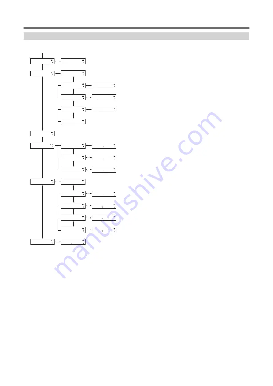
Function Menu

Press [FUNCTION].

UP-SPEED
20 cm/s 20 cm/s

OFFSET
0.250mm 0.250mm

SPEED
30 cm/s 30 cm/s

FORCE
50gf    50gf

DRYER

0

ࠑ%ࠑ%

PRINT

0

ࠑ%ࠑ%

POWER

101((

POWERFULL CL.
   AB

MEDIUM CL.
   AB

NORMAL CL.
   AB

PRINT LIGHT
 AUTO    OFF

%76%10(+)

UP-SPEED

%76%10(+)
1((5'6

%76%10(+)

SPEED

%76%10(+)
(14%'

%76%10(+)
6'56%76

*'#6'4%10(+)
&4;'4ࠑ%

*'#6'4%10(+)
24+06ࠑ%

*'#6'4%10(+)
219'410

CLEANING
MANUAL CL.

CLEANING
POWERFUL CL.

CLEANING
MEDIUM CL.

CLEANING
NORMAL CL.

CLEANING

6'5624+06

$#5'21+06
#.+)021+06

FUNCTION
PRINT LIGHT

FUNCTION

%76%10(+)

FUNCTION

*'#6'4%10(+)

FUNCTION

5*''6%76

FUNCTION
PRINT LIGHT

FUNCTION

$#5'21+06

(*1)

(*1)

(*2)

(*1) This is displayed when the width of the media is displayed after the media has been loaded.
(*2) This is not displayed when the base point is not set.

Menu List

1. Basic Information

23

Summary of Contents for TrueVIS VG2-540

Page 1: ...this operation manual are subject to change without notice This manual and the product have been prepared and tested as much as possible If you find any misprints or errors please inform Roland DG Corporation Roland DG Corporation assumes no responsibility for any direct or indirect loss or damage that may occur through use of this product regardless of any failure to perform on the part of this p...

Page 2: ...tion 48 Checking before Output 50 LAN Network Settings 50 Preventing Sedimentation in Inks 51 Pausing and Canceling Output 52 Pausing and Resuming Output 52 Canceling Output 53 Ink Pouch TR2 Cleaning Liquid Pouch Replacement 54 Out of ink Warnings 54 Out of TR2 cleaning liquid Warnings 55 Ink Pouch Replacement 56 TR2 Cleaning Liquid Pouch Replacement 58 Chapter 2 Output Method 60 1 Printing Method...

Page 3: ...othly 148 Using Sticky Media 149 Preventing Ink Discharge Issues 150 Preventing Soiling of the Media Dot Drop out and Dot Displacement 150 Preventing Misaligned Media 151 Use Middle Pinch Rollers When Pulling Back or Feeding Media 151 Adjusting the Ink drying Method 152 What Is the Media Heating System 152 Setting the Print Heater Temperature 153 Setting the Dryer Temperature 154 Hints and Tips fo...

Page 4: ...ortant Notes on Using the Operation Application 200 Other Useful Functions 202 Using the Print Light Interior Light 202 Performing Printing Tests Arranged Horizontally 203 Using Media Flanges for Paper Tubes Cores with an Internal Diameter of 2 Inches 204 3 Optimizing Operation Management 205 Managing the Operations Appropriately and Efficiently 206 Setting the Current Date Time and Using It for M...

Page 5: ... 262 Replacing the Blade 262 Replacing the Separating Knife 269 Chapter 5 Troubleshooting Methods 271 1 Output Quality Problems 272 Printed Results Are Coarse or Contain Horizontal Stripes 273 Do the print heads cause dot drop out 273 Is the print head height appropriate 273 Have you carried out feed correction 273 Have you carried out correction of the ink landing position MEDIA GAP ADJ 273 Is th...

Page 6: ...tached 284 Was the media loaded while the print heater was hot 284 Are the media heating system temperatures too high 284 Is the temperature of the room too low 284 Is the humidity of the room too high 284 Is the media sagging 284 Media Feeding Is Not Straight 285 Is the media loaded and set up straight and securely 285 Media Feeding Is Not Smooth 286 Is some other object coming into contact with ...

Page 7: ...tion Panel 297 Messages 298 1 2 3 4 5 6 7 8 298 CLOSE COVER FRONT COVER COVER L COVER R 298 SHEET NOT LOADED PRESS SETUP KEY 298 CLOSE SLOT COVER 298 END OF THE SHEET 298 EMPTY DRAIN BOTTLE 298 INSTALL DRAIN BOTTLE 298 NOW HEATING NOW PROCESSING 298 TIME FOR MAINTENANCE 298 TIME FOR WIPER REPLACE 299 SET CL LIQUID FOR WIPER 299 CHANGE CL LIQUID FOR WIPER 299 TIME FOR TRAY CLEANING 299 HEAD PROTECT...

Page 8: ...y Cleaning Liquid 309 Step 4 Securing the Print Heads in Place Using the Retainer 311 Step 5 Reinstalling the Machine 312 2 Main Specifications 313 Printing Cutting Area 314 Maximum Area 314 Maximum Printing Area When Using Crop Marks 315 Media Separation Location during Continuous Printing 316 About the Blade 317 3 MEMO 318 Contents 7 ...

Page 9: ...Chapter 1 Basic Handling Methods 8 ...

Page 10: ...and Functions 10 Printer Unit 10 Operation Panel 15 Display Screen 16 About the Media Used 17 Types of Media 17 Conditions for Usable Media 18 Menu List 19 Main Menu 19 Function Menu 23 Language and Unit Menu 24 1 Basic Information 9 ...

Page 11: ...loading media In all other situations keep the front cover closed Small article storage This is a useful space in which you can place small articles Loading lever front Operate this when you load media Operation Panel The panel containing the buttons used to operate the machine P 15 Operation Panel Left cover Open this when you perform maintenance Right cover Open this when you perform maintenance...

Page 12: ...ff Power cord connector Use this to connect the power cable Loading lever rear Operate this when you load media Media holders Use these when you load media Shafts Media stays Drain bottle Discharged fluid is stored in this bottle Part Names and Functions 1 Basic Information 11 ...

Page 13: ...Function overview Cleaning liquid slot Insert the pouch tray with the TR2 cleaning liquid pouch into this slot Ethernet connector Use this to connect an Ethernet cable Part Names and Functions 12 1 Basic Information ...

Page 14: ...nch roller left pinch roller right pinch roller and middle pinch roller These clamp the media when the loading lever is lowered These rollers are called the left pinch roller the right pinch roller and the middle pinch roller according to their positions Media clamp This clamps the edge of the media to keep it from coming loose It also prevents fuzz on the cut edge of the media from touching the p...

Page 15: ...error is not ad dressed the print heads may be damaged TEMPERATURE IS TOO LOW C The ambient temperature in the printer s installation location has fall en below the temperature in which operation is possible If this error is not addressed the printer may malfunction TEMPERATURE IS TOO HIGH C The ambient temperature in the printer s installation location has ris en above the temperature in which op...

Page 16: ...ng the setting menu for cleaning of the print heads printing tests and so on FUNCTION PAUSE PAUSE key This pauses the printing opera tion It lights when operation is paused PAUSE Cursor keys Use these to select settings for menu items to move the media and for other such operations BUSY BUSY light This lamp lights up during print ing and other such operations BUSY SETUP SETUP light This lights whe...

Page 17: ...mark You can select settings and switch screens by pressing the cursor keys indicating directions ENTER mark Press ENTER to set the selected setting or execute the processing Present value The present value before change is displayed Setting value Select the setting you want to set after change Part Names and Functions 16 1 Basic Information ...

Page 18: ...s machine Roll media Media wound onto a paper tube Sheet media Media not wound onto a paper tube such as standard size media Various paper types of roll media and sheet media are selectable according to your purpose For detailed informa tion about each media contact your media supplier About the Media Used 1 Basic Information 17 ...

Page 19: ...ies to both roll and sheet media 2 To use 2 inch media the optional media flanges are required For information about optional items contact your author ized Roland DG Corporation dealer or visit our website http www rolanddg com Maximum Roll Weight 64 inch model 40 kg 88 lb 54 inch model 30 kg 66 lb If using the take up unit this specification depends on the conditions of the take up unit Other Co...

Page 20: ...66 0 5 66 0 01 6 5 66 0 6 56 24 06 SAVE NAME8 SAVE NAME1 LOAD NAME8 LOAD NAME1 PRESET 2 6 56 24 06 CALIBRATION SETTING SUB MENU PERIODIC CL 57 07 7 9 6 5 57 07 8 77 219 4 57 07 5 0 06 48 57 07 6 6 10 6 19 2 6 5 66 0 2 5 2 5 66 0 PRESET SAVE PRESET LOAD PRESET NAME1 CALIBRATION 6 56 24 06 MENU SUB MENU MENU 6 MENU CALIBRATION MENU MEDIA GAP ADJ MENU PRESET MENU 5 66 0 Menu List 1 Basic Information ...

Page 21: ... 0 MAINTENANCE 4 2 0 MAINTENANCE 4 2 9 2 4 0 10614 4 7 6 0 0 10614 2 4 0 10614 572 4 SLEEP INTERVAL CLOCK 6 CLOCK 6 2 0 0 5 761 2 0 0 5 4 5 5 0 PERIODIC CL 06 48 6 PERIODIC CL 06 48 1 PERIODIC CL PAGE 5 56 0 1 5 4 01 5 56 0 1 1 57 07 6 56 24 06 215 SUB MENU MAINTENANCE 57 07 0 10641 SUB MENU SLEEP SUB MENU CLOCK 57 07 614 7 6 57 07 2 0 57 07 761 2 0 57 07 4 5 MENU 5 56 0 1 Menu List 20 1 Basic Inf...

Page 22: ...5 0 5 6 0 6 O O DRYING TIME P C DRYING TIME PRINT 19 4 0 5 5 126 10 4 4 5 0 PREHEATING ࠑ 07 14 4 P C 14 4 24 06 BLUETOOTH DISABLE NETWORK MAC ADDRESS NETWORK 6 9 4 NETWORK SUBNET MASK NETWORK IP ADDRESS FIRMWARE Ver X XX INK XXXX XXXX XXXX 766 0 07 24 06 76 5 6 4 0 761 52 5 6 4 0 5 6 0 6 5 6 4 0 24 06 1 1 2 3 4 5 6 7 8 6 4 07 4 0 6 6 4 07 19 4 0 6 4 07 126 10 4 4 6 4 07 24 6 0 6 4 07 14 4 5 56 0 1...

Page 23: ...06 76 10 6 56 24 06 24 06 10 766 0 24 14 1 0 07 18 4 76 5 5 PREFEED 5 0 CALIBRATION SCAN SETTING CALIBRATION FEED SETTING 4125 05 5 05 4125 05 5 05 8 4125 05 5 05 412 76 6 56 24 06 412 76 SETTING 412 76 6 56 24 06 766 0 07 766 0 24 14 766 0 07 18 4 76 766 0 07 24 766 0 07 CALIBRATION 766 0 07 4125 05 766 0 07 412 76 Menu List 22 1 Basic Information ...

Page 24: ... 10 6 56 76 6 4 10 4 4 ࠑ 6 4 10 24 06 ࠑ 6 4 10 219 4 10 CLEANING MANUAL CL CLEANING POWERFUL CL CLEANING MEDIUM CL CLEANING NORMAL CL CLEANING 6 56 24 06 5 21 06 0 21 06 FUNCTION PRINT LIGHT FUNCTION 76 10 FUNCTION 6 4 10 FUNCTION 5 6 76 FUNCTION PRINT LIGHT FUNCTION 5 21 06 1 1 2 1 This is displayed when the width of the media is displayed after the media has been loaded 2 This is not displayed w...

Page 25: ...Language and Unit Menu Hold down MENU and switch on the sub power 6 2 70 6 ޕ ޕ 0 6 70 6 OO 0 MENU LANGUAGE JAPANESE Menu List 24 1 Basic Information ...

Page 26: ...to Do First after Installation 48 Accurately Adjusting the Misalignment of the Ink Landing Position 48 Checking before Output 50 LAN Network Settings 50 Preventing Sedimentation in Inks 51 Pausing and Canceling Output 52 Pausing and Resuming Output 52 Canceling Output 53 Ink Pouch TR2 Cleaning Liquid Pouch Replacement 54 Out of ink Warnings 54 Out of TR2 cleaning liquid Warnings 55 Ink Pouch Repla...

Page 27: ...witch off the sub power The continued application of heat at a single location may cause the release of toxic gases from the me dia or pose a fire hazard Procedure 1 Close the front cover 2 Turn on the main power switch 3 Press the sub power button Power Supply Operations 26 2 Basic Operations ...

Page 28: ...n may cause the release of toxic gases from the me dia or pose a fire hazard Procedure 1 Switch off the sub power whenever printing is finished Hold down the sub power switch for one second or longer 2 Raise the loading lever and remove the media When not using the machine raise the loading lever even if the sub power is on Power Supply Operations 2 Basic Operations 27 ...

Page 29: ...e breakdown of this machine such as the breakdown of the print heads Never switch off the main power or unplug the power cord suddenly while operation is in progress Switching off the main power or unplugging the power cord suddenly while operation is in progress may damage the print heads Be sure to first switch off the sub power If the main power is accidentally switched off immediately turn the...

Page 30: ...de the sub power switch flashes slowly Using the oper ation panel or performing operations such as sending print data from the computer restores the machine to its normal mode This sleep mode setting can be changed However we recommend setting the activation time for sleep mode to 30 minutes or less to reduce power consumption and prevent problems such as overheating RELATED LINKS P 211 Setting th...

Page 31: ...ernatively the media may fall out of the machine 1 Install the media on the media holders The media holder of this machine is designed to be used exclusively with media that has a paper tube core with an inner diameter of 3 inches To use 2 inch media the optional media flanges are required For information about optional items contact your authorized Roland DG Corporation dealer or visit our websit...

Page 32: ...ng period of time Doing so may lead to the media becoming deformed Exercise caution 5 Fit the paper tube core of the media onto the end cap of the left media holder 6 Move the right media holder to fit its end cap onto the paper tube core of the media Fit the paper tube onto the media holders securely to prevent the media from moving easily Setup of Media 2 Basic Operations 31 ...

Page 33: ...n place Do not secure them in place just yet IMPORTANT Do not touch the media holder adjuster The media holder adjuster is an important part that adjusts the position of the media When this machine is installed a suitably qualified worker performs an optimal adjustment that matches the installation environment Changing the adjusted position of the media holder adjuster may lead to the media feedin...

Page 34: ...o not hold places other than those instructed Do not move the media by holding it directly Otherwise the media may fall off the media holder and cause injury IMPORTANT Firmly decide the left and right side positions of the media at this point After this procedure is completed if the left and right side positions do not fit the proper positions when securing the media with pinch rollers you will ha...

Page 35: ... in place At this time the message PRESS ENTER KEY TO SETUP is displayed on the screen but do not press the ENTER yet and proceed to the next step 5 Move to the front of the printer Gently hold down the media and raise the loading lever front The media is released 6 Pull out the media over the apron Setup of Media 34 2 Basic Operations ...

Page 36: ...Setup of Media 2 Basic Operations 35 ...

Page 37: ...he force with which the media is pinched varies between the middle pinch rollers and the left and right pinch rollers Using the middle pinch rollers to pinch the media will lead to unstable media feeding If you want to readjust the media position before securing it in place redo the procedure from step 2 1 If you just hold the media to readjust its position forcibly the media will be skewed during...

Page 38: ...inting or will come loose which will have an effect on the printing quality MEMO The middle pinch roller will not lower onto the three grit rollers from the right end Place the middle pinch roller on a grit roller other than these three There may be extra middle pinch rollers depending on the width of the media being used Move the extra middle pinch rollers to positions where no grit patterns are ...

Page 39: ...ure to keep it straight and all areas of the media to be taut 5 Lower the loading lever front The media is held in place 6 Line up the edges of the media with the centers of the holes of the media clamps left and right Setup of Media 38 2 Basic Operations ...

Page 40: ...n is called initialization When initialization ends SETUP on the operation panel lights and the printable width is displayed on the screen This completes the setup of the media IMPORTANT Remove when not using roll media Do not leave roll media loaded on the machine for a long period of time Be sure to remove and store the media when not in use Leaving the roll media loaded on the machine for a lon...

Page 41: ...the media sheet media Procedure 1 Open the front cover 2 Move the media clamps to the outside of the grit rollers on the left and right edges respectively 3 Loosen the retaining screws of the media holders and then draw them to the left and right ends respectively 4 Pass the leading edge of the media between the pinch rollers and the grit rollers Setup of Media 40 2 Basic Operations ...

Page 42: ...ETUP is displayed on the screen but do not press the ENTER yet and proceed to the next step 6 Open the front cover 7 Move to the front of the printer Gently hold down the media and raise the loading lever front The media is released 8 Pull out the media over the apron Setup of Media 2 Basic Operations 41 ...

Page 43: ...Setup of Media 42 2 Basic Operations ...

Page 44: ...e of the media Point Be sure to use the left and right pinch rollers The force with which the media is pinched varies between the middle pinch rollers and the left and right pinch rollers Using the middle pinch rollers to pinch the media will lead to unstable media feeding To move the pinch rollers push down close to the rail 3 Move the middle pinch rollers over all the remaining grit rollers cove...

Page 45: ...dle pinch rollers the media will be skewed during printing or will come loose which will have an effect on the printing quality MEMO The middle pinch roller will not lower onto the three grit rollers from the right end Place the middle pinch roller on a grit roller other than these three Setup of Media 44 2 Basic Operations ...

Page 46: ...Where no grit patterns are present the middle pinch rollers will not come down 4 Straighten the media Align the media with the line indicated with the arrow in the following figure 5 Lower the loading lever front The media is held in place 6 Line up the edges of the media with the centers of the holes of the media clamps left and right Setup of Media 2 Basic Operations 45 ...

Page 47: ...ESS ENTER TO PERFORM SETUP message is displayed on the screen 8 Press ENTER When you press ENTER the cutting carriage moves and detects the width of the media This operation is called initialization When initialization ends SETUP on the operation panel lights and the printable width is displayed on the screen This completes the setup of the media Setup of Media 46 2 Basic Operations ...

Page 48: ...a separation after output has finished For information on how to configure the settings refer to the documentation for the software RIP you are using IMPORTANT Separation Operations When performing separation do not use to pull the media back If the distance from the end of the media to the separation location is short separation may not be performed smoothly Give Attention to the Media Compositio...

Page 49: ...n to display the screen shown below MEDIA GAP ADJ DETAIL SETTING 4 Press to display the screen shown below MEDIA GAP ADJ TEST PRINT 5 Press ENTER Printing of the test pattern starts 6 When printing is finished press then to display the screen shown below H1 H2 H3 0 0 0 7 View the printed test pattern and then determine the correction values from MEDIA GAP ADJ NO 1 H1 to MEDIA GAP ADJ NO 1 H4 Selec...

Page 50: ...NO 2 H4 in the same manner as step 11 Press to display the screen shown below MEDIA GAP ADJ TEST PRINT 12 Press ENTER Printing of the test pattern starts 13 Check the test pattern to see whether the correction was successful For all the correction values check that the misalignment is minimized for the two vertical lines indicated by that is the current correction value If the misalignment is smal...

Page 51: ...D on the LAN connector located on the side of the printer is lit in green Activity LED This flashes yellow while data is being received from the network Status LED This indicates the status of the communication function When it lights in green communication is possible Checking before Output 50 2 Basic Operations ...

Page 52: ...ng the day s operations be sure to carry out the above steps Allowing the ink to stand without carrying out these steps can cause the settled material to harden resulting in malfunction or other problems IMPORTANT Do not remove the ink pouches Shake the entire pouch tray Removing the ink pouches may lead to the ink leaking Before shaking wipe off any ink from around the mouth of the ink pouch If y...

Page 53: ...not recommend resuming printing because horizontal stripes are produced at the place where printing was paused Procedure 1 Press PAUSE before printing finishes This pauses the printing operation 2 Press PAUSE again The printing operation resumes Pausing and Canceling Output 52 2 Basic Operations ...

Page 54: ...pauses the printing operation 2 When the screen shown below appears hold down PAUSE for 1 second or longer TO CANCEL HOLD DOWN PAUSE KEY This cancels the printing operation 3 Stop sending the output data from the computer Pausing and Canceling Output 2 Basic Operations 53 ...

Page 55: ... If both inks of the same color run out the numbers of the color that has run out flash Lit Indicates that ink still remains Flashing Indicates that ink has run out Off Indicates an ink pouch that is currently not in use IMPORTANT Never reuse an ink pouch when the machine shows a sign indicating no ink Occasionally the machine will show a sign indicating no ink even if there is a small amount of i...

Page 56: ...ing liquid slot light flashes After some time a message requesting that you replace the TR2 cleaning liquid will be displayed on the screen CHANGE SOLCL LIQUID CL LIQUID FOR WIPER indicates the TR2 cleaning liquid Ink Pouch TR2 Cleaning Liquid Pouch Replacement 2 Basic Operations 55 ...

Page 57: ... to replace each pouch with an item of identical type and color Never use an ink pouch that has already been used in another machine even if it is an identical type Never mix different types of items Never leave the machine with a pouch tray removed The print heads may become clogged Do not insert or remove pouch trays unless necessary Ink may leak Take care not to drop ink pouches Procedure 1 Ope...

Page 58: ... do not use it Such an ink pouch is in a state where drawing ink from it is impossible Using it in such a state may force air into the ink path and cause printer malfunctions 6 Set the pouch tray in the ink slot Insert the ink tray as far as it will go IMPORTANT Do not insert empty pouch trays Doing so may force air into the ink path and cause printer malfunctions Check the color names indicated o...

Page 59: ...ach of children Such locations present the risk of fire occur ring Accidental ingestion by children may pose a health hazard Procedure 1 Remove the pouch tray from the cleaning liquid slot 2 Remove the TR2 cleaning liquid pouch from the pouch tray 3 Set the new TR2 cleaning liquid pouch in the pouch tray Check that the hook has caught on the edge 4 Set the pouch tray in the cleaning liquid slot In...

Page 60: ...Ink Pouch TR2 Cleaning Liquid Pouch Replacement 2 Basic Operations 59 ...

Page 61: ...Chapter 2 Output Method 60 ...

Page 62: ...1 Printing Method Preparations before Printing Output 62 Printing Tests and Normal Cleaning 62 Printing Output 65 Step 1 Batch Settings for Printing 65 Step 2 Starting Output 74 1 Printing Method 61 ...

Page 63: ...2nd and later tests in comparison to the 1st test P 203 Performing Printing Tests Arranged Horizontally Procedure 1 Load the media P 30 Setup of Media 2 Press FUNCTION 3 Press then to display the screen shown below CLEANING TEST PRINT 4 Press ENTER Printing of the test pattern starts 5 Check whether there is dot drop out or dot displacement in the test pattern Missing blocks indicate dot drop out ...

Page 64: ...ht 4 Press 5 Select the group of print heads to clean 1 Press or to select the group of print heads that is not to be cleaned NORMAL CL AB 2 Press or to get rid of the group display NORMAL CL A 3 Repeat steps 1 and 2 to display only the group of print heads that requires cleaning Only the displayed groups will be cleaned If A and B are displayed they will both be cleaned 6 Press ENTER to confirm y...

Page 65: ... corrected If the problem persists try performing normal cleaning again If the printer has been used for a long period dot drop outs may not be fixed even after performing normal cleaning two or three times If this is the case clean using a different method RELATED LINKS P 231 When Normal Cleaning Is Not Effective Preparations before Printing Output 64 1 Printing Method ...

Page 66: ...ave the setting details as a preset Note that you can set all the items set here individually as well 1 Start the MEDIA SETTING menu Procedure 1 Load the media Check that the media is not sagging If any sagging exists settings such as the correction values will not function effectively 2 Press MENU 3 Press ENTER MENU MEDIA SETTING If you want to cancel the batch settings before they are completed ...

Page 67: ...et the PRINT HEATER temperature Recommended temperature 40 C 104 F PRINT HEATER 30 C 40 C 2 Press ENTER to confirm your entry 3 Press or to set the DRYER temperature Recommended temperature 45 C 113 F 4 Press ENTER to confirm your entry Printing Output 66 1 Printing Method ...

Page 68: ...n of the height adjustment lever the display screen changes and the buzzer sounds at the same time Position Display Screen HIGH HEAD HEIGHT LOW HIGH MIDDLE HEAD HEIGHT LOW MIDDLE LOW HEAD HEIGHT LOW LOW MEMO Normally move the height adjustment lever to LOW For media that is wrinkled or comes loose from the platen move the height adjustment lever to MEDIUM or HIGH The printing quality degrades as t...

Page 69: ...determine the correction value Current correction value Select the value to make the gap and overlap between the up per lower squares smallest In the case of the following figure select 0 40 When you cannot choose be tween two sequential numbers specify a value that is between them 5 Press or to select the correction value CALIBRATION 0 00 0 05 6 Press ENTER to confirm your entry 7 Press to select...

Page 70: ...REDO ADJ YES DONE 10 Press ENTER to confirm your entry Printing Output 1 Printing Method 69 ...

Page 71: ... between two sequential numbers select a value that is between them you can set correction values in units of 0 5 5 Press or to select the correction value MEDIA GAP ADJ 0 5 6 Press ENTER to confirm your entry 7 Press to select SET REDO ADJ YES DONE 8 Press ENTER to confirm your entry The test pattern is printed again Check that the gap and overlap are the smallest for the figure indicated by that...

Page 72: ... after the 1st page is printed The next operation is not started until the set time passes DRYING TIME 10min 10min MEMO This setting is enabled for output data designed only for printing This setting is ignored for output data designed for printing and cutting When the drying time has been set in the software RIP priority is given to the software RIP s setting Example of setting time general guide...

Page 73: ...for the machine 3 Press or to select a destination to save the preset You can select a name from NAME1 to NAME8 SAVE TO NAME1 4 Press ENTER to confirm your entry 5 Set the name 1 Press or to select a character 2 Press to move to the next character 3 Set the following characters in the same way You can enter up to15 characters SET NAME 6 Press ENTER to confirm your entry 7 Press MENU to go back to ...

Page 74: ...ES NO 3 Press ENTER to confirm your entry The screen shown below appears again MENU MEDIA SETTING Selecting NO in step 2 returns you to the screen that was displayed when you pressed MENU MEMO Even if you cancel media settings before they are completed the values set so far will be saved Printing Output 1 Printing Method 73 ...

Page 75: ...the ink pouches Shake the entire pouch tray Removing the ink pouches may lead to the ink leaking Before shaking wipe off any ink from around the mouth of the ink pouch If you do not wipe off the ink it may splatter when you shake the pouch tray When you have finished mixing the ink reinsert the pouch tray immediately Taking time to reattach the ink cartridge will adversely affect the ink path Even...

Page 76: ...er and Dryer Together Data from the computer is not accepted when you are not at the top menu Points that must be observed Never open a cover front left or right while output is in progress Doing so interrupts printing When you are performing printing clamp the edges of the media with the media clamps Otherwise the edges of the media may warp and catch on the print heads During output do not touch...

Page 77: ...utput 77 Step 1 Switching Off the Print Heater and Dryer 77 Step 2 Preventing Pulling of the Media with Undue Force 78 Step 3 Adjusting Cutting 79 Cutting Output 81 Step 1 Batch Settings for Cutting 81 Step 2 Starting Output 88 76 2 Cutting Method ...

Page 78: ...ION HEATER CONFIG 3 Press to display the screen shown below HEATER CONFIG POWER ON 4 Press 5 Press or to select OFF HEATER CONFIG ON OFF 6 Press ENTER to confirm your entry The settings for the print heater and dryer are turned off 7 Press FUNCTION to go back to the original screen Preparations before Cutting Output 2 Cutting Method 77 ...

Page 79: ...ss once and then press several times to display the screen shown below CUTTING MENU PREFEED 4 Press to display the screen shown below PREFEED DISABLE DISABLE 5 Press or to select ENABLE PREFEED DISABLE ENABLE 6 Press ENTER to confirm your entry 7 Press MENU to go back to the original screen Preparations before Cutting Output 78 2 Cutting Method ...

Page 80: ...ress several times to display the screen shown below FUNCTION CUT CONFIG 6 Press to display the screen shown below CUT CONFIG TEST CUT 7 Press ENTER The test pattern is cut 8 Press to display the screen shown below CUT CONFIG FORCE 9 Press to display the screen shown below FORCE 50gf 50gf 10 Peel off the cut shapes to verify the cutting quality Two shapes are peeled off separately You do not need ...

Page 81: ...ress ENTER The test pattern is cut 15 Check whether the correction was successful At the CUT CONFIG menu you can also make settings for other cutting conditions in addition to the blade force Refer to the following page RELATED LINKS P 163 Fine tuning the Cutting Conditions Preparations before Cutting Output 80 2 Cutting Method ...

Page 82: ...ave the setting details as a preset Note that you can set all the items set here individually as well 1 Start the MEDIA SETTING menu Procedure 1 Load the media Check that the media is not sagging If any sagging exists settings such as the correction values will not function effectively 2 Press MENU 3 Press ENTER MENU MEDIA SETTING If you want to cancel the batch settings before they are completed ...

Page 83: ...t heater and dryer Procedure 1 Press or to select OFF PRINT HEATER 30 C OFF 2 Press ENTER to confirm your entry 3 Press or to select OFF DRYER 30 C OFF 4 Press ENTER to confirm your entry Cutting Output 82 2 Cutting Method ...

Page 84: ... confirm your entry 7 Press to select YES CROP CUT ADJ SET NEXT 8 Press ENTER to confirm your entry 9 Press to select YES CUT FORCE SET NEXT 10 Press ENTER to confirm your entry The test pattern is cut You can select NEXT and press ENTER to skip the current menu and proceed to the next menu 11 Peel off the two cut shapes a circle and a square 12 Check how the two shapes peel off Two shapes are pee...

Page 85: ...0gf 60gf 15 Press ENTER to confirm your entry The test pattern is cut again Check the result 16 Check how the two shapes peel off Two shapes are peeled off together backing paper is also cut Press to select YES CONTINUE ADJ YES DONE Two shapes are peeled off separately Press to select DONE CONTINUE ADJ YES DONE 17 Press ENTER to confirm your entry If you select YES the test pattern is cut again Go...

Page 86: ...VE PRESET SAVE NEXT 7 Press ENTER to confirm your entry If you select NEXT and press ENTER the screen in step 12 is displayed and the settings you have selected up to this point are not saved as a preset However they will remain as the current setting values for the machine 8 Press or to select a destination to save the preset You can select a name from NAME1 to NAME8 SAVE TO NAME1 9 Press ENTER t...

Page 87: ...12 Press MENU to go back to the original screen COMPLETED This completes the operation of the MEDIA SETTING menu Cutting Output 86 2 Cutting Method ...

Page 88: ...YES NO 3 Press ENTER to confirm your entry The screen shown below appears again MENU MEDIA SETTING Selecting NO in step 2 returns you to the screen that was displayed when you pressed MENU MEMO Even if you cancel media settings before they are completed the values set so far will be saved Cutting Output 2 Cutting Method 87 ...

Page 89: ...The machine does not run when a cover front left right or ink slot is open Data from the computer is not accepted when SETUP is dark Data from the computer is not accepted when you are not at the top menu Points that must be observed Never open a cover front left or right while output is in progress Doing so interrupts printing During output do not touch the media Doing so may obstruct the media f...

Page 90: ...ore Printing and Cutting Output 90 Step 1 Printing Tests and Normal Cleaning 90 Step 2 Adjusting Cutting 93 Printing and Cutting Output 95 Step 1 Batch Settings for Printing and Cutting 95 Step 2 Starting Output 108 3 Printing and Cutting Method 89 ...

Page 91: ...later tests in comparison to the 1st test P 203 Performing Printing Tests Arranged Horizontally Procedure 1 Load the media P 30 Setup of Media 2 Press FUNCTION 3 Press then to display the screen shown below CLEANING TEST PRINT 4 Press ENTER Printing of the test pattern starts 5 Check whether there is dot drop out or dot displacement in the test pattern Missing blocks indicate dot drop out Collapse...

Page 92: ... Select the group of print heads to clean 1 Press or to select the group of print heads that is not to be cleaned NORMAL CL AB 2 Press or to get rid of the group display NORMAL CL A 3 Repeat steps 1 and 2 to display only the group of print heads that requires cleaning Only the displayed groups will be cleaned If A and B are displayed they will both be cleaned 6 Press ENTER to confirm your entry Th...

Page 93: ...f the problem persists try performing normal cleaning again If the printer has been used for a long period dot drop outs may not be fixed even after performing normal cleaning two or three times If this is the case clean using a different method RELATED LINKS P 231 When Normal Cleaning Is Not Effective Preparations before Printing and Cutting Output 92 3 Printing and Cutting Method ...

Page 94: ...times to display the screen shown below FUNCTION CUT CONFIG 6 Press to display the screen shown below CUT CONFIG TEST CUT 7 Press ENTER The test pattern is cut 8 Press to display the screen shown below CUT CONFIG FORCE 9 Press to display the screen shown below FORCE 50gf 50gf 10 Peel off the cut shapes to verify the cutting quality Two shapes are peeled off separately You do not need to perform th...

Page 95: ...e test pattern is cut 15 Check whether the correction was successful At the CUT CONFIG menu you can also make settings for other cutting conditions in addition to the blade force Refer to the following page RELATED LINKS P 163 Fine tuning the Cutting Conditions Preparations before Printing and Cutting Output 94 3 Printing and Cutting Method ...

Page 96: ...e setting details as a preset Note that you can set all the items set here individually as well 1 Start the MEDIA SETTING menu Procedure 1 Load the media Check that the media is not sagging If any sagging exists settings such as the correction values will not function effectively 2 Press MENU 3 Press ENTER MENU MEDIA SETTING If you want to cancel the batch settings before they are completed see th...

Page 97: ... HEATER temperature Recommended temperature 40 C 104 F PRINT HEATER 30 C 40 C 2 Press ENTER to confirm your entry 3 Press or to set the DRYER temperature Recommended temperature 45 C 113 F 4 Press ENTER to confirm your entry Printing and Cutting Output 96 3 Printing and Cutting Method ...

Page 98: ...ght adjustment lever the display screen changes and the buzzer sounds at the same time Position Display Screen HIGH HEAD HEIGHT LOW HIGH MIDDLE HEAD HEIGHT LOW MIDDLE LOW HEAD HEIGHT LOW LOW MEMO Normally move the height adjustment lever to LOW For media that is wrinkled or comes loose from the platen move the height adjustment lever to MEDIUM or HIGH The printing quality degrades as the distance ...

Page 99: ...e correction value Current correction value Select the value to make the gap and overlap between the up per lower squares smallest In the case of the following figure select 0 40 When you cannot choose be tween two sequential numbers specify a value that is between them 5 Press or to select the correction value CALIBRATION 0 00 0 05 6 Press ENTER to confirm your entry 7 Press to select SET REDO AD...

Page 100: ...REDO ADJ YES DONE 10 Press ENTER to confirm your entry Printing and Cutting Output 3 Printing and Cutting Method 99 ...

Page 101: ... sequential numbers select a value that is between them you can set correction values in units of 0 5 5 Press or to select the correction value MEDIA GAP ADJ 0 5 6 Press ENTER to confirm your entry 7 Press to select SET REDO ADJ YES DONE 8 Press ENTER to confirm your entry The test pattern is printed again Check that the gap and overlap are the smallest for the figure indicated by that is the curr...

Page 102: ...l off Two shapes are peeled off together backing paper is also cut Press to select YES CONTINUE ADJ YES DONE Two shapes are peeled off separately Press to select DONE CONTINUE ADJ YES DONE 7 Press ENTER to confirm your entry If you select YES proceed to the next procedure If you select DONE proceed to step 7 Correct the misalignment of the printing and cutting positions P 103 8 Press or to adjust ...

Page 103: ...d off separately Press to select DONE CONTINUE ADJ YES DONE 11 Press ENTER to confirm your entry If you select YES the test pattern is cut again Go back to step 12 and perform the setting again If you select DONE proceed to step 7 Correct the misalignment of the printing and cutting positions P 103 Printing and Cutting Output 102 3 Printing and Cutting Method ...

Page 104: ...xample of the printing position and the cutting position being misaligned is shown in the following figure F indicates the feed direction of the media the feed direction and S indicates the direction of print head movement the scan direction 4 Determine whether to correct the misalignment Cutting position and printing position are not aligned Press to select YES CONTINUE ADJ YES DONE Cutting posit...

Page 105: ...ttern P C1 is printed and cut again Check the condition of the test pattern to check whether the printing position and the cutting position are aligned 9 Determine whether to correct the misalignment Cutting position and printing position are not aligned Press to select YES CONTINUE ADJ YES DONE Cutting position and printing position are aligned Press to select DONE CONTINUE ADJ YES DONE 10 Press ...

Page 106: ...tting is enabled for output data designed only for printing This setting is ignored for output data designed for printing and cutting When the drying time has been set in the software RIP priority is given to the software RIP s setting Example of setting time general guide The setting time varies according to the settings such as the type of media and the printing quality Condition Non coated viny...

Page 107: ...ine 3 Press or to select a destination to save the preset You can select a name from NAME1 to NAME8 SAVE TO NAME1 4 Press ENTER to confirm your entry 5 Set the name 1 Press or to select a character 2 Press to move to the next character 3 Set the following characters in the same way You can enter up to15 characters SET NAME 6 Press ENTER to confirm your entry 7 Press MENU to go back to the original...

Page 108: ... ENTER to confirm your entry The screen shown below appears again MENU MEDIA SETTING Selecting NO in step 2 returns you to the screen that was displayed when you pressed MENU MEMO Even if you cancel media settings before they are completed the values set so far will be saved Printing and Cutting Output 3 Printing and Cutting Method 107 ...

Page 109: ...es Shake the entire pouch tray Removing the ink pouches may lead to the ink leaking Before shaking wipe off any ink from around the mouth of the ink pouch If you do not wipe off the ink it may splatter when you shake the pouch tray When you have finished mixing the ink reinsert the pouch tray immediately Taking time to reattach the ink cartridge will adversely affect the ink path Even if you rarel...

Page 110: ... Together Data from the computer is not accepted when you are not at the top menu Points that must be observed Never open a cover front left or right while output is in progress Doing so interrupts printing When you are performing printing clamp the edges of the media with the media clamps Otherwise the edges of the media may warp and catch on the print heads During output do not touch the media D...

Page 111: ...1 Step 1 Printing Tests and Normal Cleaning 112 Step 2 Adjusting Cutting 115 Cutting with Crop Marks 117 Step 1 Batch Settings for Cutting with Crop Marks 117 Step 2 Starting Output with Crop Marks 130 Step 3 Preparations for Cutting Output 132 Step 4 Starting Cutting Output 136 110 4 How to Cut with Crop Marks ...

Page 112: ...oading this media again for cutting you have to align the print ing and cutting positions By printing the data together with crop marks you can make it possible to align the positions using the crop marks when you load the media again to cut it In this manual this printing method is referred to as cutting with crop marks Preparations before Cutting with Crop Marks 4 How to Cut with Crop Marks 111 ...

Page 113: ...d later tests in comparison to the 1st test P 203 Performing Printing Tests Arranged Horizontally Procedure 1 Load the media P 30 Setup of Media 2 Press FUNCTION 3 Press then to display the screen shown below CLEANING TEST PRINT 4 Press ENTER Printing of the test pattern starts 5 Check whether there is dot drop out or dot displacement in the test pattern Missing blocks indicate dot drop out Collap...

Page 114: ... 5 Select the group of print heads to clean 1 Press or to select the group of print heads that is not to be cleaned NORMAL CL AB 2 Press or to get rid of the group display NORMAL CL A 3 Repeat steps 1 and 2 to display only the group of print heads that requires cleaning Only the displayed groups will be cleaned If A and B are displayed they will both be cleaned 6 Press ENTER to confirm your entry ...

Page 115: ... If the problem persists try performing normal cleaning again If the printer has been used for a long period dot drop outs may not be fixed even after performing normal cleaning two or three times If this is the case clean using a different method RELATED LINKS P 231 When Normal Cleaning Is Not Effective Preparations before Cutting with Crop Marks 114 4 How to Cut with Crop Marks ...

Page 116: ...l times to display the screen shown below FUNCTION CUT CONFIG 6 Press to display the screen shown below CUT CONFIG TEST CUT 7 Press ENTER The test pattern is cut 8 Press to display the screen shown below CUT CONFIG FORCE 9 Press to display the screen shown below FORCE 50gf 50gf 10 Peel off the cut shapes to verify the cutting quality Two shapes are peeled off separately You do not need to perform ...

Page 117: ...The test pattern is cut 15 Check whether the correction was successful At the CUT CONFIG menu you can also make settings for other cutting conditions in addition to the blade force Refer to the following page RELATED LINKS P 163 Fine tuning the Cutting Conditions Preparations before Cutting with Crop Marks 116 4 How to Cut with Crop Marks ...

Page 118: ... the setting details as a preset Note that you can set all the items set here individually as well 1 Start the MEDIA SETTING menu Procedure 1 Load the media Check that the media is not sagging If any sagging exists settings such as the correction values will not function effectively 2 Press MENU 3 Press ENTER MENU MEDIA SETTING If you want to cancel the batch settings before they are completed see...

Page 119: ...NT HEATER temperature Recommended temperature 40 C 104 F PRINT HEATER 30 C 40 C 2 Press ENTER to confirm your entry 3 Press or to set the DRYER temperature Recommended temperature 45 C 113 F 4 Press ENTER to confirm your entry Cutting with Crop Marks 118 4 How to Cut with Crop Marks ...

Page 120: ...eight adjustment lever the display screen changes and the buzzer sounds at the same time Position Display Screen HIGH HEAD HEIGHT LOW HIGH MIDDLE HEAD HEIGHT LOW MIDDLE LOW HEAD HEIGHT LOW LOW MEMO Normally move the height adjustment lever to LOW For media that is wrinkled or comes loose from the platen move the height adjustment lever to MEDIUM or HIGH The printing quality degrades as the distanc...

Page 121: ...the correction value Current correction value Select the value to make the gap and overlap between the up per lower squares smallest In the case of the following figure select 0 40 When you cannot choose be tween two sequential numbers specify a value that is between them 5 Press or to select the correction value CALIBRATION 0 00 0 05 6 Press ENTER to confirm your entry 7 Press to select SET REDO ...

Page 122: ...REDO ADJ YES DONE 10 Press ENTER to confirm your entry Cutting with Crop Marks 4 How to Cut with Crop Marks 121 ...

Page 123: ...correction values in units of 0 5 5 Press or to select the correction value MEDIA GAP ADJ 0 5 6 Press ENTER to confirm your entry 7 Press to select SET REDO ADJ YES DONE 8 Press ENTER to confirm your entry The test pattern is printed again Check that the gap and overlap are the smallest for the figure indicated by that is the current correction value If the gap and overlap are smaller for another ...

Page 124: ...arately Press to select DONE CONTINUE ADJ YES DONE 7 Press ENTER to confirm your entry If you select YES proceed to the next procedure If you select DONE proceed to step 7 Correct the misalignment of the printing and cutting positions when using crop marks P 125 8 Press or to adjust the blade force If the two shapes are peeled off together increase the blade force If the backing paper is also cut ...

Page 125: ...s ENTER to confirm your entry If you select YES the test pattern is cut again Go back to step 12 and perform the setting again If you select DONE proceed to step 7 Correct the misalignment of the printing and cutting positions when using crop marks P 125 Cutting with Crop Marks 124 4 How to Cut with Crop Marks ...

Page 126: ...ext step If you select NEXT proceed to step 8 5 Check the test pattern C C1 condition Check whether the printing position shaded part and the cutting position outer frame are aligned An example of the printing position and the cutting position being misaligned is shown in the following figure F indicates the feed direction of the media the feed direction and S indicates the direction of print head...

Page 127: ...e scan direction S F 0 30 0 35mm S 0 40 0 45mm 3 When you have finished setting the correction values press ENTER The test pattern C C1 is printed and cut again Check the condition of the test pattern to check whether the printing position and the cutting position are aligned 11 Determine whether to correct the misalignment Cutting position and printing position are not aligned Press to select YES...

Page 128: ...r printing This setting is ignored for output data designed for printing and cutting When the drying time has been set in the software RIP priority is given to the software RIP s setting Example of setting time general guide The setting time varies according to the settings such as the type of media and the printing quality Condition Non coated vinyl chloride media Setting time About three minutes...

Page 129: ...chine 3 Press or to select a destination to save the preset You can select a name from NAME1 to NAME8 SAVE TO NAME1 4 Press ENTER to confirm your entry 5 Set the name 1 Press or to select a character 2 Press to move to the next character 3 Set the following characters in the same way You can enter up to15 characters SET NAME 6 Press ENTER to confirm your entry 7 Press MENU to go back to the origin...

Page 130: ...ess ENTER to confirm your entry The screen shown below appears again MENU MEDIA SETTING Selecting NO in step 2 returns you to the screen that was displayed when you pressed MENU MEMO Even if you cancel media settings before they are completed the values set so far will be saved Cutting with Crop Marks 4 How to Cut with Crop Marks 129 ...

Page 131: ...e ink pouches Shake the entire pouch tray Removing the ink pouches may lead to the ink leaking Before shaking wipe off any ink from around the mouth of the ink pouch If you do not wipe off the ink it may splatter when you shake the pouch tray When you have finished mixing the ink reinsert the pouch tray immediately Taking time to reattach the ink cartridge will adversely affect the ink path Even i...

Page 132: ...er Together Data from the computer is not accepted when you are not at the top menu Points that must be observed Never open a cover front left or right while output is in progress Doing so interrupts printing When you are performing printing clamp the edges of the media with the media clamps Otherwise the edges of the media may warp and catch on the print heads During output do not touch the media...

Page 133: ...hown below FUNCTION HEATER CONFIG 3 Press to display the screen shown below HEATER CONFIG POWER ON 4 Press 5 Press or to select OFF HEATER CONFIG ON OFF 6 Press ENTER to confirm your entry The settings for the print heater and dryer are turned off 7 Press FUNCTION to go back to the original screen Cutting with Crop Marks 132 4 How to Cut with Crop Marks ...

Page 134: ...nce and then press several times to display the screen shown below CUTTING MENU PREFEED 4 Press to display the screen shown below PREFEED DISABLE DISABLE 5 Press or to select ENABLE PREFEED DISABLE ENABLE 6 Press ENTER to confirm your entry 7 Press MENU to go back to the original screen Cutting with Crop Marks 4 How to Cut with Crop Marks 133 ...

Page 135: ... several times to display the screen shown below FUNCTION CUT CONFIG 6 Press to display the screen shown below CUT CONFIG TEST CUT 7 Press ENTER The test pattern is cut 8 Press to display the screen shown below CUT CONFIG FORCE 9 Press to display the screen shown below FORCE 50gf 50gf 10 Peel off the cut shapes to verify the cutting quality Two shapes are peeled off separately You do not need to p...

Page 136: ...ENTER to confirm your entry 13 Press to display the screen shown below CUT CONFIG TEST CUT 14 Press ENTER The test pattern is cut 15 Check whether the correction was successful Cutting with Crop Marks 4 How to Cut with Crop Marks 135 ...

Page 137: ...hine does not run when a cover front left right or ink slot is open Data from the computer is not accepted when SETUP is dark Data from the computer is not accepted when you are not at the top menu Points that must be observed Never open a cover front left or right while output is in progress Doing so interrupts printing During output do not touch the media Doing so may obstruct the media feed or ...

Page 138: ...Chapter 3 Optimizing Quality and Efficiency 137 ...

Page 139: ...ng the Drying Time after Printing When Printing and Cutting 159 Switching Off the Print Heater and Dryer Together 160 Using an Auxiliary Drying Unit 161 Using a Blower fan Unit 162 Accurately Adjusting the Cutting Settings 163 Fine tuning the Cutting Conditions 163 Accurately Adjusting the Cutting in Amount 165 Performing Distance Correction during Cutting 166 Cutting to Make It Possible to Cut Co...

Page 140: ...to display the screen shown below 6 View the printed test pattern and then determine the correction value Select the value that gives the least misalignment between the two lines In the case of the following figure select 3 When you cannot choose between two sequential numbers select a value that is between them you can set correction values in units of 0 5 7 Press or to select the correction valu...

Page 141: ...ved by performing MEDIA GAP ADJ SIMPLE SETTING Adjust the misalignment of the ink landing position P 139 Procedure 1 Press MENU 2 Press several times to display the screen shown below MENU MEDIA GAP ADJ 3 Press then to display the screen shown below MEDIA GAP ADJ DETAIL SETTING 4 Press to display the screen shown below MEDIA GAP ADJ TEST PRINT 5 Press ENTER Printing of the test pattern starts 6 Wh...

Page 142: ...H4 in the same manner as step 11 Press to display the screen shown below MEDIA GAP ADJ TEST PRINT 12 Press ENTER Printing of the test pattern starts 13 Check the test pattern to see whether the correction was successful For all the correction values check that the misalignment is minimized for the two vertical lines indicated by that is the current correction value If the misalignment is smaller f...

Page 143: ...imes to find the optimal correction value Procedure 1 If using roll media check that the media is not sagging 2 Press MENU 3 Press several times to display the screen shown below MENU CALIBRATION 4 Press to display the screen shown below CALIBRATION TEST PRINT 5 Press ENTER Printing of the test pattern starts 6 When printing of the test pattern is finished press then to display the screen shown be...

Page 144: ...aller for another figure set the correction value again 13 When you have successfully performed the correction press MENU to go back to the original screen MEMO Depending on the software RIP you are using you can also configure this setting in the software RIP by for example choosing the media type When you have made the setting in the software RIP the software RIP s setting is used and the printe...

Page 145: ...creen changes and the buzzer sounds at the same time Position Display Screen HIGH HEAD HEIGHT LOW HIGH MIDDLE HEAD HEIGHT LOW MIDDLE LOW HEAD HEIGHT LOW LOW MEMO Normally move the height adjustment lever to LOW For media that is wrinkled or comes loose from the platen move the height adjustment lever to MEDIUM or HIGH The printing quality degrades as the distance between the media and the print he...

Page 146: ...Adjusting the Misalignment of the Ink Landing Position P 150 Preventing Soiling of the Media Dot Drop out and Dot Displacement Configuring Settings to Match the Properties of the Media 1 Optimizing the Output Quality 145 ...

Page 147: ...display the screen shown below SUB MENU EDGE DETECTION 4 Press to display the screen shown below EDGE DETECTION ENABLE ENABLE 5 Press or to select DISABLE 6 Press ENTER to confirm your entry 7 Press MENU to go back to the original screen MEMO Default setting ENABLE When set to DISABLE printing operation does not stop when the media runs out If media runs out while printing is in progress immediate...

Page 148: ...CAN INTERVAL OFF OFF 5 Press or to select a value Larger values cause the media to move more slowly enabling you to extend the drying time accordingly 6 Press ENTER to confirm your entry 7 Press MENU to go back to the original screen MEMO Default setting OFF Depending on the software RIP you are using you can also make this setting in the software RIP When you have made the setting in the software...

Page 149: ...POWER AUTO AUTO 5 Press or to select a value 0 to 100 When the media is flimsy and cannot move smoothly decreasing this value reducing the suction force may correct the problem AUTO The suction force is automatically adjusted to the optimal level for the media width 6 Press ENTER to confirm your entry 7 Press MENU to go back to the original screen MEMO Default setting AUTO Depending on the softwar...

Page 150: ... need to change it Procedure 1 Press MENU 2 Press several times to display the screen shown below MENU SUB MENU 3 Press once and then press several times to display the screen shown below SUB MENU MEDIA RELEASE 4 Press to display the screen shown below MEDIA RELEASE DISABLE DISABLE 5 Press or to select ENABLE 6 Press ENTER to confirm your entry 7 Press MENU to go back to the original screen MEMO D...

Page 151: ...IODIC CL NONE 5 Press or to select a setting NONE Automatic cleaning is not performed PAGE Automatic cleaning is performed each time prior to the start of printing INTERVAL JOB Automatic cleaning is performed when the cumulative printing time reaches the value you set here However if this time is reached during printing automatic cleaning is performed before the next printing opera tion starts Bec...

Page 152: ...he output quality If you set AUTO MIDDLE PINCH to DISABLE the middle pinch rollers will press down on the media while mov ing thus preventing skewing or coming loose However because the middle pinch rollers are pressed against the printed surface it is easier for the rollers to leave a trace on the printed surface Before pulling back the media make sure to dry it thoroughly P 152 Adjusting the Ink...

Page 153: ...de the media WARNING Never use the dryer for any purpose for which it is not intended such as to dry clothing Doing so may cause overheating resulting in fire or accident IMPORTANT Use the machine in an environment with an ambient temperature of 20 to 32 C 68 to 90 F If the machine is used at an ambient temperature lower than 20 C 68 F then depending on the type or width of the media wrinkling or ...

Page 154: ...n shown below FUNCTION HEATER CONFIG 3 Press or to display the screen shown below HEATER CONFIG PRINT 40 C 4 Press to display the screen shown below PRINT 40 C 40 C 5 Press or to select the temperature If the ink forms lumps or smudges raise the temperature Note however that a temperature that is too high may degrade the media or cause it to wrinkle You can also set the temperature to OFF When set...

Page 155: ...play the screen shown below FUNCTION HEATER CONFIG 3 Press once and then press twice to display the screen shown below HEATER CONFIG DRYER 40 C 4 Press to display the screen shown below DRYER 50 C 50 C 5 Press or to select the temperature When ink drying is poor raise the temperature Note however that a temperature that is too high may de grade the media or cause it to wrinkle You can also set the...

Page 156: ...he software RIP to higher image quality Conversely if you want to use a faster print quality raise the temperature Amount of ink When you change the amount of ink using the settings for your software RIP adjusting this may yield better re sults If problems such as smudging persist even after raising the temperature try reducing the amount of ink Other points to remember When recommended settings f...

Page 157: ...REHEATING 4 Press to display the screen shown below PREHEATING 30 C 30 C 5 Press or to select a setting MENU The system performs heating to the set temperature at all times without lowering the tempera ture during preheating 30 C The system maintains a temperature of 30 C 86 F during preheating OFF The system switches the media heating system off during preheating 6 Press ENTER to confirm your ent...

Page 158: ...BLE 5 Press or to select ENABLE or DISABLE ENABLE Media feed is performed until the trailing edge of the printing area is positioned on the dryer The margin between the print end position and the next print start position is set to a value of 100 mm 3 9 in when OPTION DRYER is set to DISABLE and 280 mm 11 1 in when it is set to ENABLE P 161 Using an Auxiliary Drying Unit DISABLE Media feed stops w...

Page 159: ...ess ENTER to confirm your entry 8 Press MENU to go back to the original screen MEMO Default setting 0 min The next operation is not started until the set time elapses During drying PAUSE is lit Press PAUSE while PAUSE is lit to finish the drying time and start the next operation Hold down PAUSE while PAUSE is lit to cancel the output When the drying time has been set in the software RIP priority i...

Page 160: ...reen MEMO Default setting 0 min The next operation is not started until the set time elapses During drying PAUSE is lit Press PAUSE while PAUSE is lit to finish the drying time and start the next operation Hold down PAUSE while PAUSE is lit to cancel the output When you have configured this setting we recommend setting the FEED FOR DRY menu to ENABLE or P C This setting is also applied during prin...

Page 161: ...mes to display the screen shown below FUNCTION HEATER CONFIG 3 Press to display the screen shown below HEATER CONFIG POWER ON 4 Press 5 Press or to select OFF HEATER CONFIG ON OFF 6 Press ENTER to confirm your entry The settings for the print heater and dryer are turned off 7 Press FUNCTION to go back to the original screen MEMO Default setting ON IMPORTANT When this is set to OFF the heater will ...

Page 162: ...ION DRYER 4 Press to display the screen shown below OPTION DRYER DISABLE DISABLE 5 Press or to select ENABLE 6 Press ENTER to confirm your entry 7 Press MENU to go back to the original screen MEMO Default setting DISABLE For recommended auxiliary drying unit models contact your authorized Roland DG Corporation dealer or visit our website http www rolanddg com For details on how to use the auxiliar...

Page 163: ...OWER FAN 4 Press to display the screen shown below BLOWER FAN DISABLE DISABLE 5 Press or to select ENABLE 6 Press ENTER to confirm your entry 7 Press MENU to go back to the original screen MEMO Default setting DISABLE For recommended blower fan unit models contact your authorized Roland DG Corporation dealer or visit our website http www rolanddg com For details on how to use the blower fan unit r...

Page 164: ...UNCTION CUT CONFIG 5 Press to display the screen shown below CUT CONFIG TEST CUT 6 Press ENTER The test pattern is cut 7 When the cutting of the test pattern is finished press 8 Check the results of the cutting test Check item Result Setting item Adjustment Check the shape The cut shape is distorted SPEED Reduce Peel off the circle The square also peels off FORCE Increase Some uncut areas remain S...

Page 165: ... blade travels when it moves to the next cutting line after cutting one cutting line If the media comes loose during no load feed and the blade damages the surface of the media reduce the speed 30 cm s 10 Press to display the screen shown below FORCE 50gf 50gf SPEED 30 cm s 30 cm s OFFSET 0 250mm 0 250mm UP SPEED 20 cm s 20 cm s 11 Press or to select a value 12 Press ENTER to confirm your entry 13...

Page 166: ... you are using media that has poor ink adhesion properties The amount of blade extension is 0 mm at minimum and 2 5 mm 98 4 mil at maximum Rough Estimate for the Amount of Blade Extension When Creating a Sticker Set the amount of blade extension to an amount that is the sum of the thickness of the material portion and half the thickness of the backing paper Rough Estimate for the Amount of Blade E...

Page 167: ...o display the screen shown below CUTTING MENU CALIBRATION 4 Press twice to display the screen shown below FEED SETTING 0 00 0 00 5 Press or to select the correction value Set the correction value of the media feed direction FEED SETTING 0 00 0 10 6 Press ENTER to confirm your entry 7 Press then to display the screen shown below CALIBRATION SCAN SETTING 8 Press to display the screen shown below SCA...

Page 168: ... stick ers easier to peel off Procedure 1 Press MENU 2 Press to display the screen shown below MENU CUTTING MENU 3 Press once and then press several times to display the screen shown below CUTTING MENU OVER CUT 4 Press to display the screen shown below OVER CUT DISABLE DISABLE 5 Press or to select ENABLE 6 Press ENTER to confirm your entry 7 Press MENU to go back to the original screen MEMO Defaul...

Page 169: ...PRIOR 4 Press to display the screen shown below CUTTING PRIOR COMMAND COMMAND 5 Press or to select MENU Prioritize the cutting conditions set on the machine over the software RIP settings If this is set to COMMAND priority is given to the software RIP settings CUTTING PRIOR COMMAND MENU 6 Press ENTER to confirm your entry 7 Press MENU to go back to the original screen MEMO Default setting COMMAND ...

Page 170: ...he screen shown below 6 View the printed test pattern and then determine the correction value Select the value that gives the least misalignment between the two lines In the case of the following figure select 3 When you cannot choose between two sequential numbers select a value that is between them you can set correction values in units of 0 5 7 Press or to select the correction value 8 Press EN...

Page 171: ... Check whether the printing position shaded part and the cutting position outer frame are aligned An example of the printing position and the cutting position being misaligned is shown in the following figure F indicates the feed direction of the media the feed direction and S indicates the direction of print head movement the scan direction If the printing position and the cutting position are al...

Page 172: ...11 Press MENU then to display the screen shown below PRINT CUT ADJ TEST PRINT 12 Press ENTER The test pattern P C1 is printed and cut If the printing and cutting lines are aligned adjustment is com plete If further adjustment is needed press then to go back to step 10 and fine tune the adjust ment MEMO Default settings F correction value of the media feed direction 0 00 mm S correction value of th...

Page 173: ...G PRINT CUT ADJ 5 Press 6 Determine the correction values MEMO Determine the values so as to correct the misalignment of the cutting position in relation to the printing position In the case of the following figure feed direction F is misaligned in a negative direction and scan direction S in a positive direction Therefore set the correction values for the feed direction F to positive values and t...

Page 174: ...r longer to cancel the cutting operation P 52 Pausing and Canceling Output MEMO Default settings F correction value of the media feed direction 0 00 mm S correction value of the cutting carriage movement direction 0 00 mm Accurately Adjusting the Settings for Printing and Cutting 1 Optimizing the Output Quality 173 ...

Page 175: ... points are determined with reference to the location of the base point as shown in the following figure You cannot set the align points unless you specify the base point Redoing the setting for the base point clears any align points that have been set Procedure 1 Press or to move the center of the blade to the base point position 2 Press FUNCTION to display the screen shown below FUNCTION BASE PO...

Page 176: ... set The characters B1 are displayed on the screen W1100mm B1 7 Repeat steps 4 through 6 to specify align point 2 and align point 3 as required The number of the align point you are setting is determined automatically Accurately Adjusting the Settings for Cutting with Crop Marks 1 Optimizing the Output Quality 175 ...

Page 177: ...hed press then to display the screen shown below 6 View the printed test pattern and then determine the correction value Select the value that gives the least misalignment between the two lines In the case of the following figure select 3 When you cannot choose between two sequential numbers select a value that is between them you can set correction values in units of 0 5 7 Press or to select the ...

Page 178: ...es the direction of print head movement the scan direction If the printing position and the cutting position are aligned no corrections are necessary If the printing position and the cutting position are not aligned proceed to the next procedure 6 Press twice to display the screen shown below CROP CUT ADJ TEST PRINT 2 7 Press ENTER The test pattern C C2 is printed and cut 8 Press to display the sc...

Page 179: ...ed adjustment is com plete If further adjustment is needed press then to go back to step 11 and fine tune the adjust ment MEMO Default settings F correction value of the media feed direction 0 00 mm S correction value of the cutting carriage movement direction 0 00 mm Depending on the changes in the condition of media caused by laminating and the loading position of the media before cutting the po...

Page 180: ...ts 5 When printing is finished press then to display the screen shown below 6 View the printed test pattern and then determine the correction value Select the value that gives the least misalignment between the two lines In the case of the following figure select 3 When you cannot choose between two sequential numbers select a value that is between them you can set correction values in units of 0 ...

Page 181: ...5 Press ENTER Printing of the test pattern starts Only one crop mark is printed 6 When printing is finished press MENU to go back to the original screen 7 Remove any media If the media needs to be separated refer to the following page P 47 Separating the Media 8 Complete operations before cutting output for normal cutting with crop marks such as laminating Accurately Adjusting the Settings for Cut...

Page 182: ...ay the screen shown below FUNCTION BASE POINT 5 Press ENTER to confirm your entry When the screen displays the character B together with the printable width at the location as shown in the following figure setting is completed W1100mm B 6 Press MENU 7 Press to display the screen shown below MENU CUTTING MENU 8 Press then to display the screen shown below CUTTING MENU CROP CUT ADJ 9 Press twice and...

Page 183: ... direction F to positive values and the scan direction S to negative values Measure the actual misalignment amount when determining the value 3 Set the correction values for the feed direction F and the scan direction S 1 Press or to set the correction value for the feed direction F F 0 30 0 35mm S 0 40 0 45mm 2 Press or to set the correction value for the scan direction S F 0 30 0 35mm S 0 40 0 4...

Page 184: ...Correcting the Misalignment of Printing and Cutting with Crop Marks Concurrent Test for Printing and Cutting with Crop Marks Accurately Adjusting the Settings for Cutting with Crop Marks 1 Optimizing the Output Quality 183 ...

Page 185: ...own below CROPSENS CALIB SENS CALIB 6 Press ENTER to display the screen shown below MOVE CUT TOOL TO MARK CENTER 7 Press or to move the center of the blade over the crop marks The center of the blade should only be over the crop marks and does not need to be aligned with the cen ter of the crop marks 8 Press ENTER If correction succeeds the following message appears Proceed to the next step CALIB ...

Page 186: ...ome reason Redo the correction If the same message appears even after you redo correction several times contact your authorized Roland DG Corporation dealer 9 Press any one of the keys on the operation panel to display the screen shown below CROPSENS CALIB SENS CALIB Accurately Adjusting the Settings for Cutting with Crop Marks 1 Optimizing the Output Quality 185 ...

Page 187: ...essage appears CHECK FAILED MARK NOT FOUND It is possible that crop marks cannot be detected because they are not the crop marks output from the software RIP that is compatible with this machine Crop marks drawn using drawing software also cannot be detected Use the software RIP that is compatible with this machine to output the crop marks and redo the correction from the start If detection failed...

Page 188: ...ess to display the screen shown below MENU CUTTING MENU 3 Press once and then press twice to display the screen shown below CUTTING MENU CROPSENS CALIB 4 Press then to display the screen shown below CROPSENS CALIB SENS LEVEL 5 Press twice to display the screen shown below SENS LEVEL 20 20 6 Press or to set the correction value 7 Press ENTER to confirm your entry 8 Press MENU to go back to the orig...

Page 189: ... 1 Press MENU 2 Press to display the screen shown below MENU CUTTING MENU 3 Press once and then press twice to display the screen shown below CUTTING MENU CROPSENS CALIB 4 Press then to display the screen shown below CROPSENS CALIB SENS LEVEL 5 Press then to display the screen shown below SENS LEVEL RESET 6 Press ENTER to confirm your entry 7 Press MENU to go back to the original screen Accurately...

Page 190: ...e Up Unit 196 Performing Operations from the Dedicated Mobile Operation Application 197 What Is the Dedicated Mobile Operation Application 197 Downloading the Operation Application 198 Using the Operation Application 199 Important Notes on Using the Operation Application 200 Other Useful Functions 202 Using the Print Light Interior Light 202 Performing Printing Tests Arranged Horizontally 203 Usin...

Page 191: ...on the preset number 1 Press or to select one option from NAME1 to NAME8 2 Press ENTER to confirm your entry The current menu settings are saved and then the screen shown below appears SET NAME S 6 Set the preset name 1 Press or to select a character 2 When you have selected the character you want to enter press The characters you can enter are A through Z 0 through 9 and the character 3 Press or ...

Page 192: ...kles Easily Does Not Move Smoothly FULL WIDTH S P 195 Speeding Up Output for Narrow Media MEDIA RELEASE P 149 Using Sticky Media FORCE SPEED OFFSET UP SPEED P 163 Fine tuning the Cutting Conditions CALIBRATION in the CUTTING MENU P 166 Performing Distance Correction during Cutting PRINT CUT ADJ P 169 Correcting the Misalignment of Printing and Cut ting CROP CUT ADJ P 176 Correcting the Misalignmen...

Page 193: ...te SETUP returns to being lit Procedure 1 Press MENU 2 Press to display the screen shown below MENU PRESET 3 Press then to display the screen shown below LOAD NAME1 4 Select the preset that you want to load 1 Press or to select the name of the preset you want to load 2 Press ENTER to confirm your entry 5 Press MENU to go back to the original screen Using Presets 192 2 Optimizing Work Efficiency ...

Page 194: ... are using the media take up unit sold separately do not press after you finish setting up the media Pressing will cause the machine to make an emergency stop in order to protect the motor Procedure 1 Press while the following screen is displayed The cutting carriage comes out over the platen W1100mm 2 Press or to move the center of the blade to the position that you want to set as the base point ...

Page 195: ...W1100mm B Adjusting the Output start Location 194 2 Optimizing Work Efficiency ...

Page 196: ... to select SHEET or OFF FULL WIDTH S FULL OFF SHEET SHEET matches the range of print head movement to the width of the media OFF OFF matches the range of print head movement to the output data Movement is limited to the minimum amount necessary and this can be expected to yield the fastest output Note however that because the speed of media movement is no longer constant colors may be uneven FULL ...

Page 197: ...up unit hereinafter referred to as the take up unit is an optional item For information on how to assemble install and operate the take up unit refer to the take up unit user s manual Using the Media Take up Unit 196 2 Optimizing Work Efficiency ...

Page 198: ...ems iOS 10 0 or later Android 6 or later The operation application may not work on some Android devices even if their operating system is version 6 or later Supported lan guages Japanese English French German Italian Peninsular Spanish Latin American Spanish Communication method Bluetooth 4 0 LE The mobile terminal you are using must support the above communication method For the latest informatio...

Page 199: ...ration Application To download the operation application visit the Roland DG Corporation website http www rolanddg com Performing Operations from the Dedicated Mobile Operation Application 198 2 Optimizing Work Efficiency ...

Page 200: ...nication 3 Turn on Bluetooth communication on the mobile terminal you are using For information on how to configure the settings refer to the documentation for the mobile terminal you are using 4 Start the operation application Use the operation application according to the instructions shown on your mobile terminal Performing Operations from the Dedicated Mobile Operation Application 2 Optimizing...

Page 201: ...uency interference In this situation carry out the follow ing countermeasures When using Bluetooth communication to connect the printer and the mobile terminal do so at a distance of 10 m 32 8 ft or more away from the equipment in which a wireless LAN unit is installed Bring the mobile terminal and the printer as close together as possible If using Bluetooth communication within 10 m 32 8 ft of th...

Page 202: ...nal communication charges apply to the downloading of the application You will have to bear the com munication charges Note that it may take time to confirm whether this application is supported by new mobile terminals Depending on the usage environment this application may not operate normally even with mobile terminals that have been confirmed to be supported Performing Operations from the Dedic...

Page 203: ...n shown below PRINT LIGHT AUTO AUTO 4 Press or to select the status of the print light PRINT LIGHT AUTO ON AUTO The light is turned on off automatically according to the status of the printer ON The light is on at all times OFF The light is off at all times 5 Press ENTER to confirm your entry 6 Press MENU to go back to the original screen MEMO Default setting AUTO Other Useful Functions 202 2 Opti...

Page 204: ... printed with the SCAN orientation regardless of this setting Procedure 1 Press MENU 2 Press several times to display the screen shown below MENU SUB MENU 3 Press then to display the screen shown below SUB MENU TEST PRINT POS 4 Press to display the screen shown below TEST PRINT POS SCAN SCAN 5 Press or to select SCAN TEST PRINT POS SCAN FEED 6 Press ENTER to confirm your entry 7 Press ENTER to go ...

Page 205: ...n about purchasing them contact your authorized Roland DG Corporation dealer or visit our website http www rolanddg com End cap Remove the pin If it is difficult to remove the pin use a pair of pliers or a similar tool Media flange for 2 inch media Align the depression with the projection attach the media flange and then insert the pin Other Useful Functions 204 2 Optimizing Work Efficiency ...

Page 206: ...ing Every Time the Media Is Changed 208 Printing the Amount of Remaining Media 209 Thoroughly Using the Middle Pinch Rollers 210 Setting the Activation Interval for Sleep Mode Power saving Feature 211 Managing the Basic Settings of the Printer 212 Setting the Menu Language and Units of Measurement 212 Turning on Bluetooth Communication 213 Viewing System Information 214 Returning All Settings to F...

Page 207: ...hown below MENU SUB MENU 3 Press once and then press several times to display the screen shown below 4 SUB MENU CLOCK 5 Press to display the screen shown below CLOCK DATE 2016 01 01 1 Press or to set the year 2 Press 3 Press or to set the month 4 Press 5 Press or to set the day 6 Press ENTER to confirm your entry 7 Press or to display the screen shown below CLOCK TIME 01 01 59 1 Press or to set th...

Page 208: ...display the screen shown below SET LENGTH 0 0m 99 9m 5 Press or to set the current amount of media remaining SET LENGTH 0 0m 25 0m 6 Press ENTER to confirm your entry 7 Press MENU to go back to the original screen W1200mm L 25 0m SETUP SHEET ROLL L 25 0m This display is updated If media has not been loaded the set value flashes Managing the Operations Appropriately and Efficiently 3 Optimizing Ope...

Page 209: ...not displayed automatically Procedure 1 Press MENU 2 Press several times to display the screen shown below MENU SHEET REMAIN 3 Press then to display the screen shown below SHEET REMAIN AUTO DISPLAY 4 Press to display the screen shown below AUTO DISPLAY DISABLE DISABLE 5 Press or to select ENABLE AUTO DISPLAY DISABLE ENABLE 6 Press ENTER to confirm your entry If you select ENABLE you must set the E...

Page 210: ... you use the media Note however that if you continue printing the next printing operation will start on top of the portion where the amount of remaining media is printed If you want to continue printing separate the media before starting the next printing operation Procedure 1 Press MENU 2 Press several times to display the screen shown below MENU SHEET REMAIN 3 Press to display the screen shown b...

Page 211: ...o drop and the media to come loose which will lead to a decrease in the output quality If the message is displayed we recommend that you raise the loading lever and perform the setup of media again Procedure 1 Press MENU 2 Press several times to display the screen shown below MENU SUB MENU 3 Press once and then press several times to display the screen shown below SUB MENU M PINCH CHECK 4 Press 5 ...

Page 212: ...ess MENU 2 Press several times to display the screen shown below MENU SUB MENU 3 Press once and then press several times to display the screen shown below SUB MENU SLEEP 4 Press twice to display the screen shown below INTERVAL 30min 30min 5 Press or to set the time INTERVAL 30min 15min 6 Press ENTER to confirm your entry 7 Press MENU to go back to the original screen MEMO Default setting 30 min Ma...

Page 213: ...splay menu language MENU LANGUAGE ENGLISH 3 Press ENTER to confirm your entry 4 Press or to select the measurement unit for length LENGTH UNIT mm INCH 5 Press ENTER to confirm your entry 6 Press or to select the measurement unit for temperature TEMP UNIT C F 7 Press ENTER to confirm your entry MEMO Default settings MENU LANGUAGE ENGLISH LENGTH UNIT mm TEMP UNIT C Managing the Basic Settings of the...

Page 214: ...ished If you cannot oper ate this machine from the dedicated mobile operation application hereinafter referred to as the operation appli cation that you are using there is a problem with the connection environment P 295 Printer Cannot Be Operated from the Dedicated Application ENABLE Bluetooth communication is on and the printer is connected to the operation application However when this screen is...

Page 215: ...DDRESS XXX XXX XXX XXX BLUETOOTH 5 5 MAC ADDRESS XXXXXXXXXXXX 6 9 4 XXX XXX XXX XXX SUBNET MASK XXX XXX XXX XXX IP ADDRESS XXX XXX XXX XXX BLUETOOTH DISABLE NETWORK MAC ADDRESS NETWORK 6 9 4 NETWORK SUBNET MASK NETWORK IP ADDRESS FIRMWARE Ver X XX INK XXXX XXXX XXXX 5 4 01 XXXXXXX MODEL XX XXX 5 56 0 1 7 6116 5 56 0 1 0 6914 5 56 0 1 4 9 4 5 56 0 1 0 5 56 0 1 5 4 01 5 56 0 1 1 MENU 5 56 0 1 MEMO F...

Page 216: ...NIT are not returned to their factory default values Procedure 1 Press MENU 2 Press several times to display the screen shown below MENU SUB MENU 3 Press once and then press several times to display the screen shown below SUB MENU FACTORY DEFAULT 4 Press ENTER to execute the operation Managing the Basic Settings of the Printer 3 Optimizing Operation Management 215 ...

Page 217: ...Chapter 4 Maintenance 216 ...

Page 218: ...portant Notes on Handling and Use 218 Printer 218 Ink Pouches 219 Basic Maintenance Knowledge 220 Types and Timing of Maintenance 220 Measures When the Printer Is Not in Use for a Prolonged Period 221 1 Introduction 217 ...

Page 219: ... to dry out The machine prevents desiccation automatically but improper operation may render this feature inoperative Operate the machine properly as specified in this manual Never leave the machine with an ink pouch removed Remaining ink in the printer may harden and clog the print heads The print heads require various types of cleaning depending on the situation Read this manual thoroughly and p...

Page 220: ...pt to disassemble the ink pouches Never attempt to refill the ink If ink gets on your hands or clothing wash it off as soon as possible Removal may become difficult if you leave such adhered ink untreated Storage Store the ink pouches unopened in a well ventilated location at a temperature of 5 to 40 C 23 to 104 F However do not store the ink pouches for a prolonged period of time in low or high t...

Page 221: ...nced Maintenance These maintenance methods consume a large amount of ink Thoroughly read the explanation and then perform the operation at the appropriate point in time Timing Category Item Page When uneven colors are not re solved Eliminating uneven colors dot drop out and dot displacement Damper cleaning Only when the ink type is CMYKLcLmLkW P 245 When manual cleaning is not ef fective Super cle...

Page 222: ...aintenance discharges ink and cleaning liquid Install a cleaning liquid pouch and ink pouches with a sufficient amount remaining If ink or cleaning liquid is empty automatic main tenance becomes impossible P 56 Ink Pouch Replacement P 58 TR2 Cleaning Liquid Pouch Replacement Switch on the sub power once a month Switch on the sub power once a month When you turn on the power the machine automatical...

Page 223: ... the Drain Bottle Exceeds Its Capacity Limit 227 Daily Print Head Check 228 Printing Tests and Normal Cleaning 228 When Normal Cleaning Is Not Effective 231 Medium Cleaning Method 231 Powerful Cleaning Method 233 Manual Cleaning 235 When Manual Cleaning Is Necessary 235 Manual Cleaning Method 236 Consumable Products and Parts Related to Manual Cleaning 242 If Colors Are Uneven 243 Mixing the Ink b...

Page 224: ... components may cause burns IMPORTANT This machine is a precision device and is sensitive to dust and dirt Perform cleaning on a daily basis Never attempt to oil or lubricate the machine Clean by wiping with a cloth moistened by neutral detergent diluted with water then wrung dry Pinch roller These are the positions where the media is fixed in place or transported so it is easy for ink and grime t...

Page 225: ...ng cleaning switch off the sub power and wait until the heater and dryer cool approximately 30 minutes Sudden movement of the machine may cause injury or hot components may cause burns IMPORTANT This machine is a precision device and is sensitive to dust and dirt Perform cleaning on a daily basis Never attempt to oil or lubricate the machine Clean by wiping with a cloth moistened by neutral deterg...

Page 226: ...e container tightly Any spillage or vapor leakage may cause fire odor or physical distress IMPORTANT Dispose of discharged fluid properly in accordance with the laws in effect in your locale Discharged fluid is flammable and contains toxic ingredients Never attempt to incinerate discharged fluid or discard it with ordinary trash Also do not dispose of it in sewer systems rivers or streams Doing so...

Page 227: ...e drain bottle a few drops of discharged fluid may come out of the machine Exercise caution to prevent this fluid from soiling your hands or the floor 3 Quickly attach the emptied drain bottle to the machine once more 4 Press or to select YES NOW EMPTY YES NO 5 Press ENTER to confirm your entry The display returns to the original screen MEMO If you did not discard the discharged fluid and selected...

Page 228: ...pears remove the drain bottle and discard the discharged fluid EMPTY DRAIN BOTTLE CAUTION Before you detach the drain bottle be sure to wait for the screen to display EMPTY DRAIN BOTTLE After discarding the discharged fluid promptly attach the drain bot tle to the machine Failing to follow this procedure may cause discharged fluid to flow out of the tube and spill soiling your hands or the floor I...

Page 229: ... FEED horizontal printing as the print position for the 2nd and later tests in comparison to the 1st test P 203 Performing Printing Tests Arranged Horizontally Procedure 1 Load the media P 30 Setup of Media 2 Press FUNCTION 3 Press then to display the screen shown below CLEANING TEST PRINT 4 Press ENTER Printing of the test pattern starts 5 Check whether there is dot drop out or dot displacement i...

Page 230: ... light 4 Press 5 Select the group of print heads to clean 1 Press or to select the group of print heads that is not to be cleaned NORMAL CL AB 2 Press or to get rid of the group display NORMAL CL A 3 Repeat steps 1 and 2 to display only the group of print heads that requires cleaning Only the displayed groups will be cleaned If A and B are displayed they will both be cleaned 6 Press ENTER to confi...

Page 231: ...been corrected If the problem persists try performing normal cleaning again If the printer has been used for a long period dot drop outs may not be fixed even after performing normal cleaning two or three times If this is the case clean using a different method RELATED LINKS P 231 When Normal Cleaning Is Not Effective Daily Print Head Check 230 2 Regular maintenance ...

Page 232: ...n below CLEANING TEST PRINT 4 Press ENTER A test pattern is printed 5 Press several times to display the screen shown below CLEANING MEDIUM CL 6 Press to display the screen shown below MEDIUM CL AB 7 Check for the group with dot drop out or dot displacement by viewing the results of the printing test The space from A to B is group A The space from B to the right side is group B MEMO If the printin...

Page 233: ...creen shown below appears again MEDIUM CL AB 10 Press once and then press several times to display the screen shown below CLEANING TEST PRINT 11 Press ENTER Perform a printing test again to check whether the dot drop out and dot displacement have been corrected MEMO If the problem persists try performing medium cleaning again If problems such as dot drop out and dot displacement persist even after...

Page 234: ... CLEANING TEST PRINT 4 Press ENTER A test pattern is printed 5 Press several times to display the screen shown below CLEANING POWERFUL CL 6 Press to display the screen shown below POWERFULL CL AB 7 Check for the group with dot drop out or dot displacement by viewing the results of the printing test The space from A to B is group A The space from B to the right side is group B MEMO If the printing ...

Page 235: ...creen shown below appears again POWERFULL CL AB 10 Press once and then press several times to display the screen shown below CLEANING TEST PRINT 11 Press ENTER Perform a printing test again to check whether the dot drop out and dot displacement have been corrected MEMO If the problem persists try performing powerful cleaning again This cleaning can be effective when carried out periodically accord...

Page 236: ...t Be Improved with Powerful Cleaning Occur When any of the symptoms given below occur and powerful cleaning is not effective perform manual cleaning Dot drop out Dot displacement Ink drips Dragging dirt Dust or other foreign matter adheres to the print heads and impedes correct ink dis charge Ink pools in dust or dirt adhered to the print heads and drips onto the media The phenomenon where dirt or...

Page 237: ... will deteriorate the cleaning liquid Never rub the print head surface nozzle surface Stroke the sponges very gently applying as little pressure as possible Never rub scrape or crush them If you use up the cleaning sticks or cleaning liquid contact your authorized Roland DG Corporation dealer or visit our website http www rolanddg com If a warning beep sounds during cleaning A warning beep sounds ...

Page 238: ...ricity 7 Moisten the cleaning stick with the cleaning liquid IMPORTANT Be sure to use one of the included cleaning sticks 8 Clean the locations shown in the following figure Be especially careful to clean away any fibrous dust lint 9 When you have finished cleaning close the right cover Manual Cleaning 2 Regular maintenance 237 ...

Page 239: ... the position where the cut rail was present Move the print head carriage by hand CAUTION When moving the print head carriage by hand be sure to hold the specified posi tion Moving it by holding positions other than that specified may deform and damage the cover Position to hold with your hand Manual Cleaning 238 2 Regular maintenance ...

Page 240: ...rous dust lint 7 When you have finished cleaning move the print head carriage to above the platen Move the print head carriage by hand CAUTION When moving the print head carriage by hand be sure to hold the specified posi tion Moving it by holding positions other than that specified may deform and damage the cover Position to hold with your hand 8 Attach the cut rail Manual Cleaning 2 Regular main...

Page 241: ...e approximate remaining time for the proce dure is displayed on the screen The display shown below is an example 01 45 1 minute and 45 sec onds CLEANING 01 45 When cleaning finishes the screen shown below appears again CLEANING MANUAL CL 12 Press FUNCTION to go back to the original screen Manual Cleaning 240 2 Regular maintenance ...

Page 242: ...n Missing blocks indicate dot drop out Collapsed or inclined blocks indicate dot displacement 6 If you have opened the front cover close it If no dot drop out or dot displacement occurs this operation is finished Press FUNCTION to go back to the original screen If dot drop out or dot displacement is present perform cleaning such as normal cleaning RELATED LINKS P 228 Printing Tests and Normal Clea...

Page 243: ...ning sticks and cleaning liquid used for manual cleaning contact your authorized Roland DG Corporation dealer or visit our website http www rolanddg com The print heads are components that wear out Periodic replacement is required with the frequency of re placement depending on use Contact your authorized Roland DG Corporation dealer Manual Cleaning 242 2 Regular maintenance ...

Page 244: ...king Before shaking wipe off any ink from around the mouth of the ink pouch If you do not wipe off the ink it may splatter when you shake the pouch tray When you have finished mixing the ink reinsert the pouch tray immediately Taking time to reattach the ink cartridge will adversely affect the ink path If uneven color issues are not resolved even after shaking the pouch trays to mix the ink perfor...

Page 245: ...White Ink 245 Damper Cleaning Method 245 Handling Severe Dot Drop out and Dot Displacement 247 Super Cleaning Method 247 Partially Restricting the Print Heads Used for Printing 252 Emergency Measure Cleaning the Print Head Surface 254 244 3 Advanced Maintenance ...

Page 246: ...oved can still be used in operations other than damper cleaning such as printing Procedure 1 Press MENU 2 Press several times to display the screen shown below MENU SUB MENU 3 Press once and then press several times to display the screen shown below SUB MENU INK CONTROL 4 Press once and then press several times to display the screen shown below INK CONTORL DAMPER CL 5 Press ENTER The screen shown ...

Page 247: ...ow out of the tube and spill soiling your hands or the floor WARNING Never place discharged fluid or ink near an open flame Doing so may cause fire CAUTION To store discharged fluid temporarily place it in the included drain bottle or in a du rable sealed container such as a metal can or polyethylene tank and cap the con tainer tightly Any spillage or vapor leakage may cause fire odor or physical ...

Page 248: ...rop out dot displacement and uneven colors cannot be corrected even after performing cleaning using the other cleaning functions normal medium powerful manual and damper cleaning RELATED LINKS P 228 Printing Tests and Normal Cleaning P 231 Medium Cleaning Method P 233 Powerful Cleaning Method P 235 Manual Cleaning 1 Perform a printing test Procedure 1 Load the media P 30 Setup of Media 2 Press FUN...

Page 249: ...When the printing test is finished the screen shown below appears Remove the media at this point CLEANING TEST PRINT Handling Severe Dot Drop out and Dot Displacement 248 3 Advanced Maintenance ...

Page 250: ...are difficult to interpret Check the results in a bright location changing your line of vision It is visible using the reflection of the light 7 Select the group of print heads to clean 1 Press or to select the group of print heads that is not to be cleaned SUPER CL AB 2 Press or to get rid of the group display SUPER CL A 3 Repeat steps 1 and 2 to display only the group of print heads that require...

Page 251: ...the included drain bottle or in a du rable sealed container such as a metal can or polyethylene tank and cap the con tainer tightly Any spillage or vapor leakage may cause fire odor or physical distress IMPORTANT Dispose of discharged fluid properly in accordance with the laws in effect in your locale Discharged fluid is flammable and contains toxic ingredients Never attempt to incinerate discharg...

Page 252: ...cate dot drop out Collapsed or inclined blocks indicate dot displacement 6 If you have opened the front cover close it If no dot drop out or dot displacement occurs this operation is finished Press FUNCTION to go back to the original screen If dot drop out or dot displacement is present perform medium cleaning If the results are still the same even after you perform super cleaning a few times cont...

Page 253: ...t use Versa Works to select the nozzle group used for printing 1 Perform a printing test for the nozzle mask Procedure 1 Load the media 2 Press FUNCTION 3 Press once and then press twice to display the screen shown below TEST PRINT NOZZLE MASK 4 Press ENTER Printing of the test pattern starts 5 Check for the nozzle group with dot drop out or dot displacement by viewing the results of the printing ...

Page 254: ...eads will be limited 4 Click Advanced The Advanced dialog box appears 5 Select the nozzle group to use in printing from the printing test results 6 Click OK Close the Advanced dialog box 7 Click OK Close the Printer Settings dialog box The icon is displayed on top of the image of the printer whose setting has been changed Handling Severe Dot Drop out and Dot Displacement 3 Advanced Maintenance 253...

Page 255: ...y damage defect free parts depending on the symptoms worsening the symptoms If you have any questions contact your authorized Roland DG Corporation dealer Procedure 1 Apply a large amount of cleaning liquid to the cleaning stick 2 Very gently touch the cleaning stick against the print head surface nozzle surface Very softly press the cleaning stick against the print head so that cleaning liquid so...

Page 256: ...lacing Parts for Maintenance 256 Replacing the Wiper and the Tray Pad 256 Cleaning the Wiper Tray 259 Replacing the Blade Separating Knife 262 Replacing the Blade 262 Replacing the Separating Knife 269 4 Replacing Consumable Parts 255 ...

Page 257: ...structions Otherwise sudden movement of the machine may cause injury Required items Wipers Tray pad Tweezers Procedure 1 Press ENTER when the following screen appears TIME FOR WIPER REPLACE 2 Remove any media 3 Press MENU 4 Press several times to display the screen shown below MENU SUB MENU 5 Press once and then press several times to display the screen shown below SUB MENU MAINTENANCE 6 Press to ...

Page 258: ...e figure to discharge any static electricity 10 Replace the wipers 1 Detach the old wipers Using the tweezers unhook the wipers and then pull them up Using the tweezers to press on the hook in the hole on the wiper makes it easier to remove the wiper 2 Attach the new wipers Place the inclined end of the wiper on the back side of the machine If the wiper is installed with the incorrect orientation ...

Page 259: ...tion it will not be possible to clean the wiper correctly 12 Press ENTER 13 When the following screen is displayed close the right cover CLOSE COVER R When the following screen is displayed again the wiper replacement is finished MAINTENANCE REPLACE WIPER 14 Press MENU to go back to the original screen Replacing Parts for Maintenance 258 4 Replacing Consumable Parts ...

Page 260: ...and then press several times to display the screen shown below MAINTENANCE TRAY CLEANING 6 Press ENTER 7 When the screen shown below appears remove the drain bottle and discard the discharged fluid EMPTY DRAIN BOTTLE IMPORTANT When you remove the drain bottle a few drops of discharged fluid may come out of the machine Exercise caution to prevent this fluid from soiling your hands or the floor CAUT...

Page 261: ...lace the tray pad IMPORTANT Place the tray pad with an orientation that matches the shape of the wiper tray If you place the tray pad with the incorrect orientation it will not be possible to clean the wiper correctly 11 Close the right cover 12 Press ENTER The screen shown below appears and then the machine is filled with TR2 cleaning liquid The approximate remaining time for the procedure is dis...

Page 262: ...MAINTENANCE TRAY CLEANING 13 Press MENU to go back to the original screen Replacing Parts for Maintenance 4 Replacing Consumable Parts 261 ...

Page 263: ...ent blade Procedure 1 Remove any media 2 Press MENU 3 Press several times to display the screen shown below MENU SUB MENU 4 Press once and then press several times to display the screen shown below SUB MENU MAINTENANCE 5 Press once and then press several times to display the screen shown below MAINTENANCE REPLACE KNIFE 6 Press ENTER The cutting carriage moves to a position where blade replacement ...

Page 264: ...D 10 Install the cutting tool in the cutting carriage OK Not OK 11 Tighten the screw Tug the blade holder upward to make sure it does not come loose 12 Close the front cover 13 Press ENTER When the following screen is displayed again the blade replacement is finished Replacing the Blade Separating Knife 4 Replacing Consumable Parts 263 ...

Page 265: ...MAINTENANCE REPLACE KNIFE 14 Press MENU to go back to the original screen Replacing the Blade Separating Knife 264 4 Replacing Consumable Parts ...

Page 266: ... cutting test Check item Result Setting item Adjustment Check the shape The cut shape is distorted SPEED Reduce Peel off the circle The square also peels off FORCE Increase Some uncut areas remain SPEED Reduce Peel off the square The blade leaves faint traces on the backing paper FORCE No change The blade trace is indistinct Increase The blade trace is too deep and cuts into the back ing paper Red...

Page 267: ... the blade travels when it moves to the next cutting line after cutting one cutting line If the media comes loose during no load feed and the blade damages the surface of the media reduce the speed 30 cm s 10 Press to display the screen shown below FORCE 50gf 50gf SPEED 30 cm s 30 cm s OFFSET 0 250mm 0 250mm UP SPEED 20 cm s 20 cm s 11 Press or to select a value 12 Press ENTER to confirm your entr...

Page 268: ...e blade holder cap to touch and may soil and damage the printed surface It is important to be especially careful about this when you are using media that has poor ink adhesion properties The amount of blade extension is 0 mm at minimum and 2 5 mm 98 4 mil at maximum Rough Estimate for the Amount of Blade Extension When Creating a Sticker Set the amount of blade extension to an amount that is the s...

Page 269: ...forated lines refer to the documentation for Versa Works IMPORTANT Pushing the blade out too far will damage the blade and blade protector and hasten their deterioration so exercise caution Replacing the Blade Separating Knife 268 4 Replacing Consumable Parts ...

Page 270: ...n shown below MENU SUB MENU 4 Press once and then press several times to display the screen shown below SUB MENU MAINTENANCE 5 Press once and then press several times to display the screen shown below MAINTENANCE REPLACE KNIFE 6 Press ENTER The cutting carriage moves to a position where blade replacement is possible 7 When the following screen is displayed open the front cover OPEN FRONT COVER Pre...

Page 271: ...Loosen the screw Take care to ensure that the knife does not slip out of position at this time 12 Close the front cover 13 Press ENTER When the following screen is displayed again the blade replacement is finished MAINTENANCE REPLACE KNIFE 14 Press MENU to go back to the original screen Replacing the Blade Separating Knife 270 4 Replacing Consumable Parts ...

Page 272: ...Chapter 5 Troubleshooting Methods 271 ...

Page 273: ...h rollers or the media clamps dirty 275 Colors Are Unstable or Uneven 276 Have you tried mixing the ink by shaking the pouch trays 276 Is the media wrinkled 276 Was printing paused partway through 276 Is the printer installed in a level and stable location 276 Is the media loaded correctly 276 Are the operating parameters set to appropriate values 276 Are the settings for the PRESET menu item appr...

Page 274: ... carried out correction of the ink landing position MEDIA GAP ADJ The optimal adjustment value varies depending on the thickness of the media Set an adjustment value that is suitable for the media When further correction is required such as when adjustment made using SIMPLE SET TING does not enhance printing use DETAIL SETTING to make the correction RELATED LINKS P 139 Adjust the misalignment of t...

Page 275: ...igh quality print mode and results may also vary greatly depending on the settings of your software RIP such as the color profile selection Select settings appropriate for the media you are using Is the media loaded correctly If the media is not loaded correctly or the media feed is not smooth printing may be adversely affected Load the media correctly RELATED LINKS P 30 Setup of Roll Media P 40 S...

Page 276: ...g may cause ink to drip on the media during printing Buildup of fibrous dust lint around the heads Ink transferred to the heads due to rubbing against the media If this happens clean the print heads manually We recommend carrying out periodic head cleaning Too low humidity Use the machine in an environment with a humidity of 35 to 80 RH no condensation RELATED LINKS P 235 Manual Cleaning Are the p...

Page 277: ...nk remaining in the ink pouches Printing may also pause when data is not sent from the computer quickly enough We recommend not performing any other tasks with the computer while printing is in progress Is the printer installed in a level and stable location Never install the machine in a location where it is tilted or where it may wobble or experience vibration Also make sure that the print heads...

Page 278: ...ttings selected with the PRESET menu item are not suitable for the type of media printing may be ad versely affected Choose settings optimized for the media you are using RELATED LINKS P 190 Using Presets Colors Are Unstable or Uneven 1 Output Quality Problems 277 ...

Page 279: ...nting the greater the chance of misalignment occurring It is a good idea to keep the size of each single page to the minimum necessary Are you using media that exhibits large expansion and contraction When you are performing printing followed immediately by cutting misalignment occurs if the media expands or contracts If this happens try performing printing with crop marks and then setting the bas...

Page 280: ...ting positions may occur due to the thickness of the media or the head height Make corrections for misaligned printing and cutting for the media you are using RELATED LINKS P 169 Accurately Adjusting the Settings for Printing and Cutting Printing and Cutting Are Misaligned 1 Output Quality Problems 279 ...

Page 281: ...ed or warped 281 Is the media size too large 281 Are you using media that is likely to reflect light 281 Are you using transparent media 281 Printing and Cutting Are Misaligned 282 Have you corrected the misalignment of printing and cutting with crop marks 282 280 2 Problems in Cutting with Crop Marks ...

Page 282: ... separated into sizes that are as short as possible If the crop marks cannot be detected automatically you can perform alignment manually RELATED LINKS P 174 Aligning the Positions of Cutting with Crop Marks Manually Are you using media that is likely to reflect light The machine may not be able to read crop marks from media that is likely to reflect light Try CROPSENS CALIB the correction functio...

Page 283: ...rections for misaligned printing and cutting for the media you are using RELATED LINKS P 176 Correcting the Misalignment of Printing and Cutting with Crop Marks Concurrent Test for Printing and Cutting with Crop Marks P 179 Correcting the Misalignment of Printing and Cutting with Crop Marks Separate Test for Printing Cutting with Crop Marks Printing and Cutting Are Misaligned 282 2 Problems in Cut...

Page 284: ...4 Media Feeding Is Not Straight 285 Is the media loaded and set up straight and securely 285 Media Feeding Is Not Smooth 286 Is some other object coming into contact with the media 286 Is the media too thick 286 Are the grit rollers dirty 286 A Media Jam Occurs 287 Is an error message displayed 287 Is the media warped or wrinkled 287 Is the height of the print heads too low 287 Are the grit roller...

Page 285: ...ng media switch off the sub power and allow the platen to cool RELATED LINKS P 152 Adjusting the Ink drying Method Are the media heating system temperatures too high Set the temperatures to suitable values for the type of media RELATED LINKS P 152 Adjusting the Ink drying Method Is the temperature of the room too low The media heating system may not warm up sufficiently when the ambient temperatur...

Page 286: ...securely Feeding is not smooth when the media is not straight or is tensioned unevenly on the left and right Reload the media RELATED LINKS P 30 Setup of Roll Media P 40 Setup of Sheet Media Media Feeding Is Not Straight 3 Media Feed Problems 285 ...

Page 287: ... P 40 Setup of Sheet Media Is the media too thick Media that is too thick may not only cause an unstable feed but may scrape the print heads resulting in a malfunc tion Never use such media Are the grit rollers dirty Check to make sure the grit rollers are free of buildup of foreign material such as media scraps RELATED LINKS P 223 Cleaning the Machine Media Feeding Is Not Smooth 286 3 Media Feed ...

Page 288: ...his into account RELATED LINKS P 144 Adjusting Print Head Height to Match Media Thickness Are the grit rollers dirty Check to make sure the grit rollers are free of buildup of foreign material such as media scraps RELATED LINKS P 223 Cleaning the Machine Are the media clamps attached When you are performing printing be sure to attach the media clamps Is the media loaded and set up straight and sec...

Page 289: ...heet Media Is the media too thick Media that is too thick may not only cause an unstable feed but may scrape the print heads resulting in a malfunc tion Never use such media A Media Jam Occurs 288 3 Media Feed Problems ...

Page 290: ...of the room too low 293 Cannot Separate the Media 294 Is the separating knife installed 294 Is the cut rail installed 294 Printer Cannot Be Operated from the Dedicated Application 295 Is the printer s operation panel in use 295 Is printer side Bluetooth communication turned on 295 Is the operation application connected to a different printer 295 Is the printer side Bluetooth communication normal 2...

Page 291: ...e If the heads still do not move carry out the following emergency response measure and then contact your au thorized Roland DG Corporation dealer Procedure 1 Switch off the main power and then open the front cover 2 Open the right cover 3 Gently move the print head carriage to the home position by hand Stopping at the place where the audible click is heard locks the print head carriage in place 4...

Page 292: ...t left and right covers Is the top menu displayed Top menu W1100mm If the top menu isn t displayed output doesn t start even when data is sent from the computer To go to the top menu press MENU RELATED LINKS P 74 Step 2 Starting Output Is PAUSE lit When PAUSE is lit operation is paused To resume press PAUSE PAUSE turns off and output resumes RELATED LINKS P 52 Pausing and Canceling Output Is a mes...

Page 293: ...address for another device on the network that the port setting for the software RIP specifies the IP address set on the machine that the settings have no typing errors and for other such problems RELATED LINKS P 214 Viewing System Information Did the software RIP end abnormally Make sure the software RIP is running correctly and then switch the sub power switch off and back on Has the ink run out...

Page 294: ... Is the temperature of the room too low The media heating system may not warm up sufficiently when the ambient temperature is less than 20 C 68 F Also even when the media heating system reaches its set temperatures adequate effectiveness may not be appa rent if the media is thoroughly chilled Before printing allow the media to come to room temperature The Media Heating System Doesn t Warm Up 4 Mac...

Page 295: ... Separating Knife Is the cut rail installed If the cut rail is not installed you cannot separate the media If the cut rail is not installed remove the left cover and then install the cut rail according to the figure shown below After installing the cut rail be sure to attach the left cover Cannot Separate the Media 294 4 Machine Problems ...

Page 296: ...side Bluetooth communication normal The state of the printer s Bluetooth communication is displayed on the screen ENABLE The printer s Bluetooth communication is on and the printer is waiting for a connection to be estab lished If you cannot operate this machine from the operation application that you are using there is a prob lem with the connection environment Check the causes of other problems ...

Page 297: ...h function turned on Check the Bluetooth status of the mobile terminal For the usage method of your mobile terminal refer to its us er s manual Is there a wireless LAN unit or anything else in the vicinity that is causing Bluetooth com munication to be unstable The Bluetooth communication status may become unstable if A wireless LAN is in place in the location The devices are in the vicinity of a ...

Page 298: ...IVATED 299 Error Messages 300 ALIGN POINT POSITION INVALID 300 OPTION DRYER IS NOT CONNECTED 300 TEMPERATURE IS TOO LOW C 300 TEMPERATURE IS TOO HIGH C 300 CROPMARK ERROR NOT FOUND 300 CAN T PRINT CROP CONTINUE 300 SHEET TOO SMALL CONTINUE 301 DATA ERROR CANCELING 301 SHEET SET ERROR SET AGAIN 301 SOME MID PINCHS NOT SET RIGHT 301 PINCHROLL ERROR LOWER PINCHROLL 301 PINCHROLL ERROR INVALID LEFT RI...

Page 299: ...ge of the media was detected during operation Press any key on the operation panel to clear the message Load new media EMPTY DRAIN BOTTLE This message appears when a certain amount of discharged fluid collects in the drain bottle Discard the discharged fluid in the bottle RELATED LINKS P 226 If the Discharged Fluid Disposal Message Appears INSTALL DRAIN BOTTLE Check whether the drain bottle is ins...

Page 300: ...uid pouch is empty Quickly replace it with a new TR2 cleaning liquid pouch RELATED LINKS P 58 TR2 Cleaning Liquid Pouch Replacement TIME FOR TRAY CLEANING It is time to clean the wiper tray After verifying the message press ENTER Clean the wiper tray and then replace the tray pads RELATED LINKS P 256 Replacing the Wiper and the Tray Pad P 259 Cleaning the Wiper Tray HEAD PROTECTION ACTIVATED The i...

Page 301: ...68 to 90 F allow the machine to come to room temperature and then turn on the power TEMPERATURE IS TOO HIGH C The temperature of the location where the machine is installed has risen above the ambient temperature at which the machine can operate Operation cannot be continued Turn off the sub power The displayed temperature is the current ambient temper ature of the installation location Bring the ...

Page 302: ... for a problem with the connector cable or the computer or if the printer data has any defects a color is designated that cannot be output etc Once the problem or defect has been corrected send the data again SHEET SET ERROR SET AGAIN 1 ENTER was pressed even though the loading lever was not lowered 2 EDGE DETECTION is set to ENABLE but transparent media was loaded 1 Lower the loading lever and th...

Page 303: ...ia thickness specified in the soft ware RIP The print heads move to a location where you can operate the height adjustment lever Adjust to the displayed height and then press ENTER RELATED LINKS P 144 Adjusting Print Head Height to Match Media Thickness MOTOR ERROR TURN POWER OFF 1 A motor error occurred 2 The media has jammed 3 Has the media been pulled with excessive force 1 Operation cannot be ...

Page 304: ...amper cleaning A pouch tray was pulled out during the first ink filling procedure for the machine Operation cannot be continued Switch the sub power off by holding down the switch for one second or longer and then switch the sub power back on again Afterward redo the damper cleaning or ink filling from the start However if the printer stopped partway through damper cleaning first execute the SUPER...

Page 305: ...Chapter 6 Appendix 304 ...

Page 306: ...ng Media and the Blade Holder 306 Step 2 Circulating the Ink Only When Using White Ink 308 Step 3 Discharging the Wiper Tray Cleaning Liquid 309 Step 4 Securing the Print Heads in Place Using the Retainer 311 Step 5 Reinstalling the Machine 312 1 Operations When Moving the Unit 305 ...

Page 307: ...lted at an angle and preventing it from striking other objects After the printer is reinstalled the media holder adjuster must be adjusted by a suitably qualified worker This work must be per formed by a Roland DG worker Contact your authorized Roland DG Corporation dealer Step 1 Removing Media and the Blade Holder Procedure 1 Remove any media If any media has been loaded remove it If no media is ...

Page 308: ...8 Detach the blade holder Preparing to Move the Machine 1 Operations When Moving the Unit 307 ...

Page 309: ...ss ENTER The screen shown below appears and then the ink circulation starts The approximate remaining time for the procedure is displayed on the screen The display shown below is an example 01 45 1 minute and 45 seconds CIRCULATING INK 01 45 Depending on the timing with which the ink circulation is started the following screen may be displayed and cleaning may start When cleaning is complete the i...

Page 310: ...WARNING Never place discharged fluid or ink near an open flame Doing so may cause fire CAUTION To store discharged fluid temporarily place it in the included drain bottle or in a du rable sealed container such as a metal can or polyethylene tank and cap the con tainer tightly Any spillage or vapor leakage may cause fire odor or physical distress IMPORTANT Dispose of discharged fluid properly in ac...

Page 311: ...rarily place it in the included drain bottle or in a du rable sealed container such as a metal can or polyethylene tank and cap the con tainer tightly Any spillage or vapor leakage may cause fire odor or physical distress 11 Re attach the emptied drain bottle Preparing to Move the Machine 310 1 Operations When Moving the Unit ...

Page 312: ...ng the Print Heads in Place Using the Retainer Procedure 1 Use the retainer that was attached to the bottom of the machine during its installation Preparing to Move the Machine 1 Operations When Moving the Unit 311 ...

Page 313: ...en the machine is filled with TR2 cleaning liquid The approximate remaining time for the procedure is displayed on the screen The display shown below is an example 01 40 1 minute and 40 seconds FILLING LIQUID 01 40 MEMO If the cleaning liquid pouch is empty or is not attached the following screen will be displayed Install a cleaning liquid pouch and press ENTER SET CL LIQUID FOR WIPER Once the mac...

Page 314: ...Specifications Printing Cutting Area 314 Maximum Area 314 Maximum Printing Area When Using Crop Marks 315 Media Separation Location during Continuous Printing 316 About the Blade 317 2 Main Specifications 313 ...

Page 315: ... position of the pinch rollers A B C D E F A B C Pinch roller Printing or cutting area Printing or cutting coordinates origin 0 0 A 75 mm 3 in B 10 mm 0 4 in C 1 5 mm 0 06 in D Max 24 998 mm 984 2 in E 64 inch model Max 1 600 mm 63 in 54 inch model Max 1 346 mm 53 in F 105 mm 4 13 in Printing Cutting Area 314 2 Main Specifications ...

Page 316: ...hen crop marks are used is reduced from the maximum printing area when crop marks are not used by an amount equal to the crop marks A B A B A B A B Maximum printing area Printing area Crop mark A 12 5 mm 0 5 in B 10 mm 0 4 in Printing Cutting Area 2 Main Specifications 315 ...

Page 317: ... command for separating the media is sent from the computer the separation location on the media is as shown in the figure below A First page Second page Separation location Margin software RIP value A 75 mm 3 in Printing Cutting Area 316 2 Main Specifications ...

Page 318: ...l Signage Vinyl 50 to 150 gf 0 25 mm 0 01 in 8 000 mm 26 246 7 ft ZEC U5025 General Signage Vinyl 30 to 100 gf 0 25 mm 0 01 in 4 000 mm 13 123 4 ft Fluorescent Vinyl 120 to 200 gf 0 25 mm 0 01 in 4 000 mm 13 123 4 ft Fluorescent Vinyl 100 to 200 gf 0 25 mm 0 01 in 4 000 mm 13 123 4 ft 1 The values for Blade life are estimates for when an identical type of media is used When uncut areas remain even...

Page 319: ...ion and or other materials provided with the distribution THIS SOFTWARE IS PROVIDED BY THE COPYRIGHT HOLDERS AND CONTRIBUTORS AS IS AND ANY EXPRESS OR IMPLIED WARRANTIES INCLUDING BUT NOT LIMITED TO THE IMPLIED WARRANTIES OF MERCHANTABILITY AND FITNESS FOR A PARTICULAR PURPOSE ARE DISCLAIMED IN NO EVENT SHALL THE COPYRIGHT HOLDER OR CON TRIBUTORS BE LIABLE FOR ANY DIRECT INDIRECT INCIDENTAL SPECIA...

Reviews: