background image

94

3

Maintenance

3

Maintenance

If Colors Are Uneven

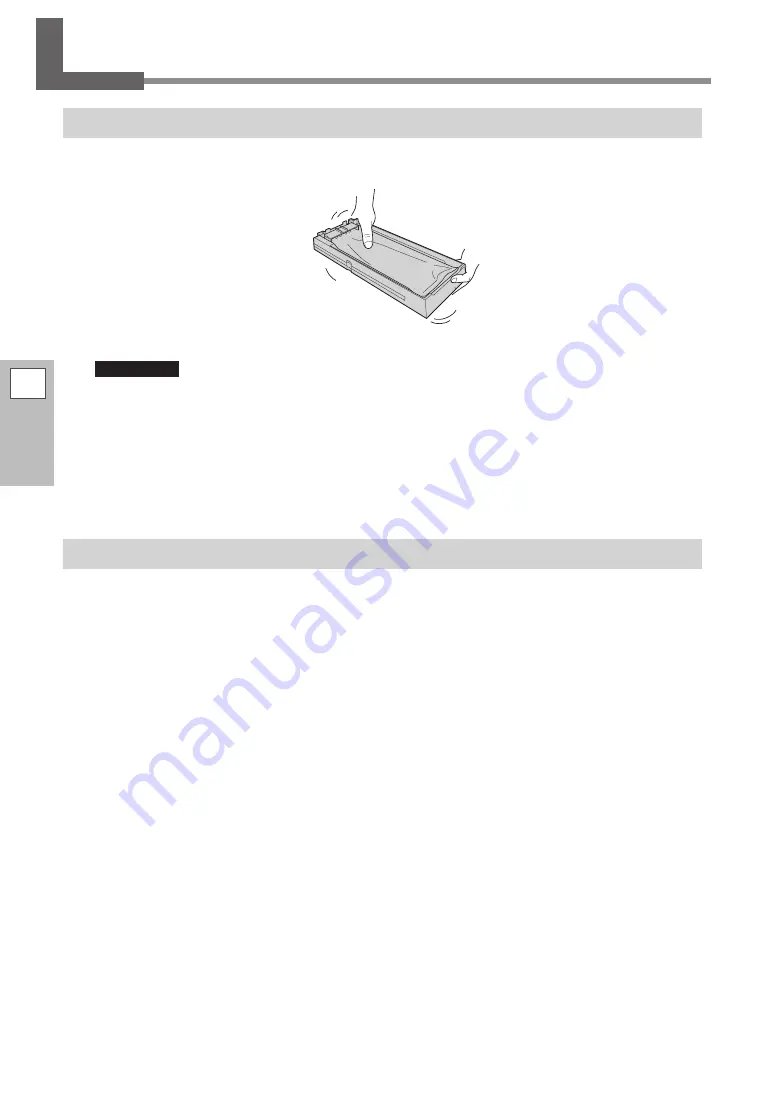
Mixing the Ink by Shaking the Pouch Tray

If ink components precipitate in the ink pouch, colors may be uneven (unevenness in printed colors). If colors 
are uneven, remove the pouch trays, and then shake them gently.

Important

•  Do not remove the ink pouches. Shake the entire pouch tray. Removing the ink pouches may lead to 

the ink leaking.

•  Before shaking an ink pouch, wipe off any ink from around the mouth of the ink pouch. If you do not 

wipe off the ink, it may splatter when you shake the pouch tray.

•  When you have finished mixing the ink, reinsert the pouch tray immediately. If you take time to reinsert 

the ink tray, the ink trays will be adversely affected.

If Colors Are Still Uneven

If uneven color issues are not resolved even after shaking the pouch trays, perform super cleaning.


"

P. 95 "Super Cleaning"

Summary of Contents for TrueVIS VG-640

Page 1: ...y misprints or errors please inform Roland DG Corp Roland DG Corp assumes no responsibility for any direct or indirect loss or damage that may occur through use of this product regardless of any failure to perform on the part of this product Roland DG Corp assumes no responsibility for any direct or indirect loss or damage that may occur with respect to any article made using this product USER S M...

Page 2: ...OF SUCH DAMAGE For the USA and Canada FCC CAUTION Changes or modifications not expressly approved by the party responsible for compliance could void the user s authority to operate the equipment This transmitter must not be co located or operated in conjunction with any other antenna or transmitter This device complies with Part 15 of FCC Rules and Industry Canada s licence exempt RSSs Operation i...

Page 3: ...ep 2 Initial Adjustment Correcting for Misalignment in Bidirectional Printing 37 Step 3 Batch Settings 39 Step 4 Setting the Base Point 53 Step 5 Printing Tests and Normal Cleaning 54 Step 6 Starting Output 57 Basic Settings for Cutting 59 Hints and Tips for Cutting Settings 59 Important Note on Cutting 59 Preventing Pulling of the Media with Undue Force 60 Setting the Cutting Test and the Blade F...

Page 4: ...rent Settings Preset Saving 114 Loading a Saved Preset 116 Settings for the Media Heating System 117 What Is the Media Heating System 117 Making the Temperature Setting for the Media Heating System 118 Setting the Temperature during Preheating 119 Drying the Trailing Edge of the Printing Area on the Dryer 120 Setting the Drying Time after Printing 121 Using an Optional Dryer 122 Using a Blower fan...

Page 5: ...tally 155 Using Media Flanges for Paper Tubes Cores with an Internal Diameter of 2 Inches 156 Chapter 5 Administrator Menu 157 Output Operation Management 158 Printing a System Report 158 Determining What Happens When Ink Runs Out 158 Displaying the Amount of Media Remaining 159 Making Sure to Verify the Setting for the Amount Remaining Every Time the Media Is Changed 160 Printing the Amount of Re...

Page 6: ...Appears 187 Chapter 7 Appendix 191 Printing Area 192 Maximum Area 192 Maximum Area When Using Crop Marks 192 The Media Cutoff Location During Continuous Printing 193 About the Blade 194 Locations of the Power Rating and Serial Number Labels 195 Specifications 196 Copyright 2015RolandDGCorporation http www rolanddg com Android Google Play are the trademarks or the registered trademarks of Google In...

Page 7: ...s Part Names and Functions 6 Printer Unit 6 Operation Panel 11 Warning Labels 12 Vignettes d avertissement 13 Menu List 14 Main Menu 14 Function Menu 18 Language and Unit Menu 19 Important Notes on Handling and Use 20 Printer Unit 20 Ink Pouches 21 5 ...

Page 8: ...ssary such as when load ing media In all other situations keep the front cover closed 3 Loading lever front Operate this when you load media 4 Panel cover operation panel Open this cover to access the operation panel Use the operation panel to operate this machine P 11 Operation Panel 5 Left cover Open this when you perform maintenance 6 Right cover Open this when you perform maintenance 7 Drain b...

Page 9: ...se this to connect the power cable 3 Loading lever rear Operate this when you load media 4 Media holders Use these when you load media 5 Shafts Use these when you load media Side No Name Function overview 1 Cleaning liquid tray slot Insert the tray with the cleaning liquid pouch into this slot 2 Ethernet connector Use this to connect an Ethernet cable ...

Page 10: ...P 9 Serious Errors Indicated by the Print Light 2 Print head carriage The print heads are inside here 3 Cutting carriage Thebladeandtheseparatingknifeareinsidehere 4 Grit rollers These rollers feed the media 5 Pinch rollers left pinch roller right pinch roller and middle pinch roller These clamp the media when the loading lever is lowered Therollersarecalledtheleftpinchroller the right pinch rolle...

Page 11: ...er occurs the print light blinks in red This indicates one of the situations shown below When the print light blinks in red the error also appears on the operation panel s display screen Check the display screen and then respond to the error according to the information in P 187 An Error Message Ap pears in this manual Display screen Error overview AVOIDING DRY UPTURN POW ER OFF The print heads we...

Page 12: ...ssage prompting you to close the cover will be displayed on the screen Follow the instruction shown on the screen and close the cover After you close the cover the following message appears on the screen Follow the instruction shown on the screen and press ENTER The machine recovers from the error and is then able to continue operations PRESS THE ENTER KEY TO CONTINUE If the message shown above do...

Page 13: ...FUNCTION FUNCTION key Press this when entering the setting menu for cleaning of the print heads printing tests and so on FUNCTION PAUSE PAUSE key This pauses the printing operation It lights when operation is paused PAUSE Cursor keys Use these to select settings for menu items to move the media and for other such operations BUSY BUSY light This lights during printing and other such operations BUSY...

Page 14: ...eyes or skin it may be hazardous to the health When performing maintenance work for example when disposing of dis charged fluid wear protective eyewear and protective gloves refer to the safety data sheet SDS Caution Pinching Hazard Be careful not to allow the fingers to become pinched when closing covers Caution High Temperature The platen and dryer become hot Exercise caution to avoid fire or bu...

Page 15: ...travaux d entretien à l élimi nation de rejets liquides par exemple utilisez une protection oculaire et des gants protec teurs se reporter à la fiche signalétique FS Attention Risque de pincement Faire attention de ne pas coincer les doigts pendant le chargement du support ou lors de la fermeture du couvercle Attention Température élevée La platine et la surface de séchage chauffent Être pru dent ...

Page 16: ...LOAD NAME8 SAVE NAME1 PRESET SAVE ADJUST BI DIR TEST PRINT ADJUST BI DIR SIMPLE SETTING ADJUST BI DIR DETAIL SETTING CALIBRATION TEST PRINT CALIBRATION SETTING HEAD HEIGHT HIGH Low SET NAME SAVE NAME8 SIMPLE SETTING 2 1 DETAIL SETTING TEST PRINT DETAIL SETTING SETTING NO 1 H1 H2 H3 0 0 02 H4 0 H1 H2 H3 0 0 0 H4 0 DETAIL SETTING SETTING NO 2 SETTING 0 00 0 05 SET NAME NAME8 MENU PRESET Continue To ...

Page 17: ...E DETECTIONプ ENABLE ENABLE SUB MENU SCAN INTERVAL SCAN INTERVAL OFF 1 0sec SUB MENU VACUUM POWER VACUUM POWER AUTO 90 SUB MENU FULL WIDTH S FULL WIDTH S FULL OFF SUB MENU PERIODIC CL PERIODIC CL NONE PERIODIC CL PAGE PERIODIC CL INTERVAL JOB INTERVAL JOB 10min 990min INTERVAL TIME 10min 990min INTERVAL 15min 15min SUPER CL AB PERIODIC CL INTERVAL TIME MEDIA RELEASE DISABLE ENABLE SLEEP INTERVAL IN...

Page 18: ...MASK 255 255 255 255 GATEWAY ADDR 255 255 255 255 GATEWAY ADDR 255 255 255 255 BLUETOOTH DISABLE BLUETOOTH DISABLE ENABLE HEATER MENU FEED FOR DRY FEED FOR DRY DISABLE ENABLE HEATER MENU PREHEATING PREHEATING 30 C MENU HEATER MENU OPTION DRYER OPTION DRYER DISABLE ENABLE HEATER MENU BLOWER FAN BLOWER FAN DISABLE ENABLE HEATER MENU DRYING TIME DRYING TIME 10min 10min MAC ADDRESS XXXXXXXXXXXX NETWOR...

Page 19: ... ADJ TEST PRINT PRINT CUT ADJ SETTING PRINT CUT ADJ TEST PRINT 2 CROP CUT ADJ TEST PRINT CROP CUT ADJ SETTING F 0 30 0 35mm S 0 40 0 40mm CALIBRATION FEED SETTING CUTTING MENU PREFEED PREFEED DISABLE ENABLE CUTTING MENU CUTTING PRIOR CUTTING PRIOR COMMAND MENU CUTTING MENU AUTO ENV MATCH AUTO ENV MATCH DISABLE ENABLE FEED SETTING 0 10 0 10 CALIBRATION SCAN SETTING SCAN SETTING 0 10 0 10 F 0 30 0 3...

Page 20: ...RCE FORCE 50 gf 50 gf CUT CONFIG SPEED SPEED 20 cm s 20 cm s CUT CONFIG OFFSET OFFSET 0 250mm 0 250mm CUT CONFIG UP SPEED UP SPEED 20 cm s 20 cm s CUT CONFIG PRINT CUT ADJ F 0 30 0 35mm S 0 40 0 40mm PRINT LIGHT AUTO OFF FUNCTION CLEANING FUNCTION CUT CONFIG FUNCTION PRINT LIGHT FUNCTION BASE POINT BASE POINT ALIGN POINT 1 CLEANING TEST PRINT CLEANING MANUAL CL FUNCTION HEATER CONFIG FUNCTION SHEE...

Page 21: ...u List 1 Machine Highlights 19 Language and Unit Menu オンド タンイ C F MENU LANGUAGE JAPANESE ナガサ タンイ ミリ インチ MENU LANGUAGE ENGLISH LENGTH UNIT mm INCH TEMP UNIT C F While holding down switch on the sub power ...

Page 22: ...he machine in a location having the specified temperature and relative humidity Install the machine in a quiet stable location offering good operating conditions The print heads are delicate Never needlessly touch or allow media to scrape them The print heads may be damaged if allowed to dry out The machine prevents desiccation automatically but improper operation may render this feature inoperati...

Page 23: ...rupture the internal pouches and cause the ink to leak Never attempt to disassemble the machine Never attempt to refill the ink If ink gets on your hands or clothing wash it off as soon as possible Removal may become difficult if you leave such adhered ink untreated Storage Store the machine unopened in a well ventilated location at a temperature of 5 to 40 C 23 to 104 F However do not store the i...

Page 24: ...22 ...

Page 25: ...5 Printing Tests and Normal Cleaning 54 Step 6 Starting Output 57 Basic Settings for Cutting 59 Hints and Tips for Cutting Settings 59 Important Note on Cutting 59 Preventing Pulling of the Media with Undue Force 60 Setting the Cutting Test and the Blade Force 61 Printing and Cutting with Crop Marks 63 What Is Printing and Cutting with Crop Marks 63 How to Print and Cut with Crop Marks 64 Printing...

Page 26: ...e any loaded media or switch off the sub power The continued application of heat at a single location may cause the release of toxic gases from the media or pose a fire hazard Procedure A Close the front cover B Switch on the main power Rear C Switch on the sub power Power Supply Operations ...

Page 27: ...tinued application of heat at a single location may cause the release of toxic gases from the media or pose a fire hazard Procedure A Switch off the sub power whenever printing is finished Hold down the sub power switch for one second or longer B Raise the loading lever and remove the media When not using the machine raise the loading lever even if the sub power is on ...

Page 28: ...he sub power If the main power is accidentally switched off immediately turn the main and sub power back on Sleep Mode Power saving Feature This machine is provided with a power saving feature that switches to a low power sleep mode when a fixed interval passes with no operation The factory default for the time after which the machine switches to sleep mode is 30 minutes When the machine is in sle...

Page 29: ...material of the media Maximum media thickness including backing paper a When performing printing only 1 0 mm 39 mil When performing cutting 0 4 mm 15 mil Roll outer diameter 210 mm 8 2 in Paper tube core inner diameter 76 2 mm 3 in or 50 8 mm 2 in b a Applies to both roll and sheet media b Touse2 inchmedia theoptionalmediaflangesarerequired Forinformationaboutoptionalitems contact your authorized ...

Page 30: ...utput as a batch Step 4 Setting the Base Point P 53 Set the base point in order to determine the output area Step 5 Printing Tests and Normal Cleaning P 54 Before you carry out actual printing ensure no dot drop out occurs If dot drop out occurs perform cleaning Step 6 Starting Output P 57 Send data from the computer and output it from the printer Theaboveprocedureisthebasicflowofprintingoperation...

Page 31: ...over 40 kg 88 lb The machine may fail to withstand the weight and tip over or cause the media to fall 1 Install the media on the media holders Note The media holders of this machine are designed to be used exclusively with media that has a paper tube core with an inner diameter of 3 inches To use 2 inch media the optional media flanges are required For information about optional items contact your...

Page 32: ... from moving easily End cap Important Position the left media holder correctly If the position of the left media holder is incorrect media may not be fed properly which will have an adverse effect on the printing results Use the following procedure to determine the appropriate position Important Do not secure the media holders in place just yet In the following procedure you will adjust the positi...

Page 33: ...of the left edge or 20 mm 0 79 in to the left of other grit patterns Leave a space of 20 mm 0 79 in or more Leave a space of 20 mm 0 79 in or more Grit pattern Place the right edge of the media within this range Grit pattern Place the left edge of the media within this range CAUTION Do not hold places other than those instructed Do not move the media by holding it directly Otherwise the media may ...

Page 34: ...e the media holders by tightening the retaining screws R L 3 Pull out the media over the platen A Pass the leading edge of the media between the pinch rollers and the grit rollers Front Grit roller Pinch roller Media B Make sure the front cover is open ...

Page 35: ...d in place At this time the message CLOSE FRONT COVER is displayed on the screen but continue operations without closing the front cover D Move to the front of the printer Gently hold down the media and raise the loading lever front The media is released E Pull out the media over the platen ...

Page 36: ...s on both edges of the media Position them approximately 10 mm 0 39 in from each edge of the media About 10 mm 0 39 in Right pinch roller affixed with a blue sticker About 10 mm 0 39 in Left pinch roller affixed with a blue sticker If you want to readjust the media position before securing it in place redo the procedure from step 2 A If you just hold the media to readjust its position forcibly the...

Page 37: ...rs Be sure to remove the remaining middle pinch rollers Grit pattern Grit roller below the media Attaching and detaching middle pinch rollers Attaching detaching location To attach Inset all the way and slide along the rail To detach Pull back and out Middle pinch roller D Hold the media at the center and pull it out being sure to keep it straight and all areas of the media to be taut ...

Page 38: ... cover is closed the print head carriage moves and detects the width of media This operation is called initialization When initialization ends SETUP on the operation panel lights and the printable width is displayed on the screen This completes the setup of the media Important Remove roll media when not in use Do not leave roll media loaded on the machine for a long period of time Be sure to remov...

Page 39: ...chine for the first time When changing the media to use When printing is not improved by performing simple correction for bidirectional printing P 124 Cor recting for Misalignment in Bidirectional Printing 1 Print the adjustment pattern for bidirectional printing A Press MENU B Press several times to display the screen shown below MENU ADJUST BI DIR C Press then to display the screen shown below A...

Page 40: ...R NO 1 H4 The test pattern is made of groups of two lines Select the value that gives the least misalignment between the two lines In the case of the following figure select 5 for H1 and H3 and 4 for H2 and H4 When you cannot choose between two sequential numbers select a value that is between them you can set correction values in units of 0 5 ...

Page 41: ...urrent correction value If the misalignment is smaller for another set of vertical lines set the correction values again H When you have successfully performed the correction press MENU to go back to the original screen Step 3 Batch Settings To ensure the optimal output according to the media size and type you can configure various settings on this machine However it is hard work to configure thes...

Page 42: ...Recommended temperature 40 C 104 F PRINT HEATER 30 C 40 C Current set temperature Temperature to be set B Press ENTER to confirm your entry C Press or to set the DRYER temperature Recommended temperature 45 C 112 F DRYER 30 C 45 C D Press ENTER to confirm your entry 3 Adjust the print head height Separate setting P 128 A Press to select CHANGE HEAD HGT LOW CHANGE NEXT B Press ENTER to confirm your...

Page 43: ...d or comes loose from the platen move the height adjustment lever to High E Close the front cover 4 Perform the position correction of the feed direction reduce horizontal stripes Separate setting P 126 MEMO Feed direction means the feed direction of the media Perform the correction adjusting to the media in advance because horizontal stripes are more likely to occur during printing when the movem...

Page 44: ...t Overlap E Press or to select the correction value CALIBRATION 0 00 0 05 F Press ENTER to confirm your entry G Press to select YES REDO ADJ YES DONE H Press ENTER to confirm your entry The test pattern is printed again Check that the gap and overlap are the smallest for the figure in dicated by that is the current correction value If the gap and overlap are smaller for another figure return to st...

Page 45: ...ceed to the next menu C Press ENTER INPUT ADJ VALUES D View the printed test pattern and then determine the correction values Select the value that gives the least misalignment between the two lines In the case of the following figure select 5 When you cannot choose between two sequential numbers select a value that is between them you can set correction values in units of 0 5 E Press or to select...

Page 46: ...orm the setting for cutting or not A Press or to select NEXT or SET Select NEXT when you will only perform printing Select SET when you will perform cutting including printing and cutting as well as crop mark printing and cutting CUT CONFIG SET NEXT B Press ENTER to confirm your entry If you select SET proceed to the next procedure If you select NEXT proceed to step 10 7 Set the blade force Separa...

Page 47: ...Press or to adjust the blade force If the two shapes are peeled off together increase the blade force If the backing paper is also cut reduce the blade force CUT FORCE 50gf 60gf G Press ENTER to confirm your entry The test pattern is cut again Check the result H Two shapes are peeled off together backing paper is also cut Press to select YES REDO ADJ YES DONE Two shapes are peeled off separately P...

Page 48: ...e two edges and in the center You can select NEXT and press ENTER to proceed to the next menu C Check the test pattern P C1 Check for misalignment in the cutting position and printing position Cutting position Printing position Printing position and cutting position are misaligned Printing position and cutting position are aligned D Cutting position and printing position are not aligned Press to s...

Page 49: ...t the correction values for the feed direction F and the scan direction S 1 Press or to set the correction value for the feed direction F F 0 30 0 30mm S 0 40 0 20mm 2 Press or to set the correction value for the scan direction S F 0 30 0 30mm S 0 40 0 20mm 3 When you have finished setting the correction values press ENTER The test pattern P C1 is printed and cut again Check the condition of the t...

Page 50: ...s depending on the composition of the media A Press or to select NEXT or SET Select NEXT when you will not print crop marks Select SET when you will print crop marks CROP CUT ADJ SET NEXT B Press ENTER to confirm your entry If you select SET the test pattern C C1 is printed and cut Proceed to the next procedure If you select NEXT proceed to step 10 C Check the test pattern C C1 condition Check for...

Page 51: ... value scale Scan direction Cutting line In this case the correction value is 0 3 Cutting line H Set the correction values for the feed direction F and the scan direction S 1 Press or to set the correction value for the feed direction F F 0 30 0 30mm S 0 40 0 20mm 2 Press or to set the correction value for the scan direction S F 0 30 0 30mm S 0 40 0 20mm 3 When you have finished setting the correc...

Page 52: ...er the 1st page is printed To make sure to dry the entire printed area select ENABLE If DISABLE is selected the trailing edge of the printing area is not fed to the dryer unless you continue with a subsequent printing operation B Press ENTER to confirm your entry C Press or to set the drying time DRYING TIME 10min 10min Current setting Setting after change MEMO Drying Time after Printing Set the d...

Page 53: ... select a destination to save the preset You can select a name from NAME1 to NAME8 SAVE TO NAME1 D Press ENTER to confirm your entry E Set the name 1 Press or to select a character 2 Press to move to the next character 3 Set the following characters in the same way You can enter up to15 characters SET NAME F Press ENTER to confirm your entry G Press MENU to go back to the original screen COMPLETED...

Page 54: ...ing Method 2 Basic Operation 52 C Press ENTER to confirm your entry The screen shown below appears again MENU MEDIA SETTING Selecting NO in step Breturns you to the screen that was displayed when you pressed MENU ...

Page 55: ...rns to its default value Print head carriage movement direction Base point right edge of the output area Output area Media feed direction MEMO Note that the left and right positions are not restored to their defaults for test patterns If you are using the media take up system sold separately do not press after you finish setting up themedia Pressing willcausethemachinetomakeanemergencystopinordert...

Page 56: ...Whenperformingprintingtestssuccessively youcanselect SCAN verticalprinting or FEED horizontal printing as the print position for the 2nd and later tests in comparison to the 1st test P 155 Performing Printing Tests Arranged Horizontally 1 Perform a printing test A Press FUNCTION B Press then to display the screen shown below CLEANING TEST PRINT C Press ENTER A test pattern is printed D Check wheth...

Page 57: ...Select the group of print heads to clean 1 Press or to select the group of print heads that is not to be cleaned NORMAL CL AB 2 Press or to get rid of the group display NORMAL CL A 3 Repeat steps 1and 2to display only the group of print heads that requires cleaning Only the displayed groups will be cleaned If A and B are displayed they will both be cleaned F Press ENTER The screen shown below appe...

Page 58: ... its default and it will be necessary to set it again if any of the following operations are made between printing operations Sheet cutting Printing and cutting of output data you created Setup cancellation If the problem persists try performing normal cleaning again If the printer has been used for a long period dot drop outs may not be fixed even after performing normal cleaning two or three tim...

Page 59: ...it lights in green communication is possible CAUTION Never touch the print head carriage while output is in progress The print head carriage moves at high speed Coming into contact with the moving carriage may cause injury Procedure A Close the front cover B Check that SETUP is lit If SETUP is not lit the loading lever has been raised Lower the loading lever C Wait until HEATER stops flashing and ...

Page 60: ...g so interrupts printing Data from the computer is not accepted when SETUP is dark Printing does not start until HEATER lights If both PRINT HEATER and DRYER are set to OFF printing is possible even if HEATER is not lit P 117 Settings for the Media Heating System Data from the computer is not accepted when you are not at the top menu Important Points that must be observed When you are performing p...

Page 61: ... in Amount Important Note on Cutting When you are performing cutting only do not use the media clamps When you are performing cutting only remove the media clamps or move them to locations where they do not clamp the media When using roll media and only performing cutting allow the media to hang down from the rear of the machine Or set the PREFEED menu to ENABLE This prevents motor errors and the ...

Page 62: ...D DISABLE DISABLE E Press or to select ENABLE PREFEED DISABLE ENABLE F Press ENTER to confirm your entry G Press MENU to go back to the original screen Description This feeds out media according to the size of the data sent from the computer before performing cutting This makes it unnecessary to turn the media flanges by hand to feed out media every time you perform cutting Note however that this ...

Page 63: ...g test A Close the front cover B Press or to move the cutting carriage to the location where you want to carry out the cutting test You can freely set the location for the cutting test C Press FUNCTION D Press several times to display the screen shown below FUNCTION CUT CONFIG E Press to display the screen shown below CUT CONFIG TEST CUT F Press ENTER The test pattern is cut 2 Set the blade force ...

Page 64: ...next step to set the blade force D Press or to select a value Two shapes are peeled off together Raise the blade force Backing paper is also cut Reduce the blade force E Press ENTER to confirm your entry F Press FUNCTION to go back to the original screen G Repeat step 1 to check whether the correction was successful At the CUT CONFIG menu you can also make settings for other cutting conditions in ...

Page 65: ...with crop marks you can make it possible to align the positions using the crop marks when you load the media again to cut it In this manual this printing method is referred to as printing and cutting with crop marks Flow of Printing and Cutting with Crop Marks 1 Print with crop marks P 64 Print with crop marks to use as guidelines 2 Remove the printed media from the printer P 65 Remove the printed...

Page 66: ...re shown below You can set the margin value with the software RIP you re using Crop mark 1 5 mm about 0 06 in Area where output is possible Where to cut the media off 90 mm or more 3 5 in or more 22 5 mm 0 89 in Pinch roller 22 5 mm 0 89 in 80 mm or more 3 2 in or more 1 5 mm about 0 06 in Important Alignment marks and symbols drawn using a graphics program cannot be used as crop marks B Prepare t...

Page 67: ...and the cutting position is aligned with the printing position For information on how to make the setting refer to the documentation for the software RIP you re using B Load the media that you removed in step 2 in the machine again P 29 Step 1 Loading Roll Media Setup of Media Points for Loading the Media Again Place the crop marks on the blade protector Crop mark Blade protector Angled no more th...

Page 68: ...146 Aligning Positions Manually If You Want to Stop Crop Mark Detection before It Is Finished and Start Cutting Procedure A Press PAUSE during detection of crop marks The screen shown below appears and crop mark detection stops Depending on the content of the data some time may pass before detection actually stops CANCEL CROPMARK DETECTION B Press ENTER Detection stops and cutting begins If you pr...

Page 69: ...ate which color has run out as shown below If an ink pouch runs out the number of the color that has run out will flash 1 2 3 4 5 6 7 8 Lit Indicates that there is a remaining amount of ink Flashing Indicates that the ink pouch is empty If the wiper cleaning liquid runs out the wiper cleaning liquid slot light flashes After some time a message requesting that you replace the wiper cleaning liquid ...

Page 70: ...idental ingestion by children may pose a health hazard Precautions regarding Ink Pouch Replacement Be sure to replace each pouch with an item of identical type and color Never use an ink pouch that has already been used in other machines even if it is of the identical type Never mix items of different types Never leave the machine with a pouch tray removed The print heads may become clogged Do not...

Page 71: ...pouch During storage the ink components may have precipitated When replacing an ink pouch gently shake the new ink pouch to mix its contents before setting the ink pouch in the tray E Set the new ink pouch in the pouch tray Check that the hook has caught Hook F Set the pouch tray in the ink slot Insert the ink tray as far as it will go ...

Page 72: ...ccur Near bleach or any other such oxidizing agent or explosive material Any location within the reach of children Doing so may lead to a fire Accidental ingestion by children may pose a health hazard When the cleaning liquid runs out the following message will be displayed Follow the procedure shown below to replace the wiper cleaning liquid pouch CHANGE CL LIQUID FOR WIPER Procedure A Press ENTE...

Page 73: ... 2 Basic Operation 71 C Remove the cleaning liquid pouch from the tray D Set the new cleaning liquid pouch in the tray Check that the hook has caught Hook E Set the pouch tray in the cleaning liquid slot Insert the ink tray as far as it will go ...

Page 74: ...have finished loading the media SETUP lights This work is referred to as Setup of Media 1 Pull out the media over the platen A Open the front cover B Move the media clamps to the left and right ends respectively C Loosen the retaining screws of the media holders and then draw them to the left and right ends respectively Rear ...

Page 75: ...e pinch rollers and the grit rollers Front Grit roller Pinch roller Media E Make sure the front cover is open F Lower the loading lever rear The media is held in place At this time the message CLOSE FRONT COVER is displayed on the screen but continue operations without closing the front cover ...

Page 76: ...old down the media and raise the loading lever front The media is released H Pull out the media over the platen 2 Secure the media in place A Make sure both edges of the media are above the grit rollers Be sure to place the right edge of the media on the right end grit roller Grit roller ...

Page 77: ... in Right pinch roller affixed with a blue sticker About 10 mm 0 39 in Left pinch roller affixed with a blue sticker C Place the middle pinch rollers over all the remaining grit rollers covered by the media There are grit patterns wherever there are grit rollers Be sure to remove the remaining middle pinch rollers Grit pattern Grit roller below the media P 35 Attaching and detaching middle pinch r...

Page 78: ...ft and right When you are performing cutting only do not use the media clamps P 59 Important Note on Cutting G Close the front cover If the PRESS ENTER KEY TO CONTINUE message appears on the screen press ENTER When the front cover is closed the print head carriage moves and detects the width of media This operation is called initialization When initialization ends SETUP on the operation panel ligh...

Page 79: ...tion is paused B Press PAUSE again to resume printing To cancel printing go the next procedure without pressing PAUSE C When the screen shown below appears hold down PAUSE for one second or longer TO CANCEL HOLD DOWN PAUSE KEY The printing operation is canceled D Stop sending the data from the computer Cutting Off the Media Procedure A Remove the left and right media clamps B Close the front cover...

Page 80: ...press ENTER REMOVE MEDIA CLAMPS Be sure to remove the media clamps If you attempt to perform the cutoff operation while the media clamps are attached the machine will detect them and interrupt the operation Even if you enable the automatic media cutoff function in the software RIP if the media clamps are attached the machine will detect them and interrupt the operation When performing cutoff do no...

Page 81: ...ing 87 Manual Cleaning 87 If Colors Are Uneven 94 Mixing the Ink by Shaking the Pouch Tray 94 If Colors Are Still Uneven 94 When Dot Drop outs Uneven Colors Are Not Fixed 95 Super Cleaning 95 Replacing Consumable Parts 99 Replacing the Wiper 99 Cleaning the Wiper Tray and Replacing the Tray Pads 102 Replacing the Blade 106 Replacing the Separating Knife 109 When Not in Use for a Prolonged Period 1...

Page 82: ...ldup of grime Clean by wiping with a cloth moistened with neutral detergent diluted with water then wrung dry Important This machine is a precision device and is sensitive to dust and dirt Perform cleaning on a daily basis Never attempt to oil or lubricate the machine Wipe away any buildup of ink or grime on the media path Grit rollers Removebuildupofmediascraps andothermaterialusingabrush Never u...

Page 83: ...d fluid to flow out of the tube and spill soiling your hands or the floor B Quickly attach the emptied drain bottle to the machine once more C Press ENTER D Press to select YES NOW EMPTY YES NO E Press ENTER The display returns to the original screen If you select NO without discarding discharged fluid This also allows you to go back to the original screen The EMPTY DRAIN BOTTLE message disappears...

Page 84: ...n shown below SUB MENU MAINTENANCE D Press then to display the screen shown below MAINTENANCE DRAIN BOTTLE E Press ENTER F When the screen shown below appears remove the drain bottle and discard the dis charged fluid EMPTY DRAIN BOTTLE CAUTION Before you detach the drain bottle be sure to wait for the screen to display EMPTY DRAIN BOTTLE After discarding the discharged fluid promptly attach the dr...

Page 85: ...e to Check the Amount of Discharged Fluid in the Drain Bottle Sometimes ink affixes to the inside of the drain bottle which makes it difficult to check the amount of dis charged fluid In this situation clean the inside of the drain bottle by using one of the following procedures Procedure A Scrape the inside of the drain bottle clean using one of the included cleaning sticks Dispose of used cleani...

Page 86: ...tep 5 Printing Tests and Normal Cleaning When Normal Cleaning Is Not Effective Medium cleaning powerful cleaning Perform medium cleaning or powerful cleaning when problems such as dot drop out are not corrected after performing normal cleaning P 85 When Normal Cleaning Is Not Effective Monthly Manual Cleaning Manual cleaning Perform manual cleaning periodically according to your frequency of use P...

Page 87: ...ing test P 54 Step 5 Printing Tests and Normal Cleaning When the printing test is finished the screen shown below appears Remove the media at this point CLEANING TEST PRINT B Press FUNCTION C Press once and then press several times to display the screen shown below When Medium is not effective select Powerful CLEANING MEDIUM CL CLEANING POWERFUL CL D Press to display the screen shown below MEDIUM ...

Page 88: ... cleaning starts The approximate re maining time for the procedure is displayed on the screen The display shown below is an example 01 45 1 minute and 45 seconds CLEANING 01 45 When finished the screen shown below appears again MEDIUM CL AB POWERFULL CL AB H Press FUNCTION to go back to the original screen I Perform a printing test again to make sure the dot drop out has been corrected P 54 Step 5...

Page 89: ...d used for manual cleaning contact your authorized Roland DG Corp dealer The print heads are components that wear out Periodic replacement is required with the frequency of replacement depending on use Contact your authorized Roland DG Corp dealer Important notes on this procedure Before attempting this operation remove any media To prevent the print heads from drying out finish this procedure in ...

Page 90: ...e from the beginning CAUTION Be sure to perform operations as specified by the instructions and never touch any area not specified in the instructions Sudden movement of the machine may cause injury Required items Cleaning stick Cleaning liquid 1 Prepare for manual cleaning A Remove any media B Press FUNCTION C Press once and then press several times to display the screen shown below CLEANING MANU...

Page 91: ...n the following screen is displayed remove the cut rail REMOVE CUT RAIL G Press ENTER H When the following screen is displayed close the left cover CLOSE COVER L Click I When the following screen is displayed open the left cover OPEN COVER L ...

Page 92: ...s complete once the following screen is displayed FINISHED 2 Clean the wiper and the area around the print heads A Touch the location shown in the figure to discharge any static electricity B Moisten the cleaning stick with the cleaning liquid Important Be sure to perform cleaning using one of the included cleaning sticks ...

Page 93: ...C Clean the locations shown in the following figure Be especially careful to clean away any fibrous dust lint Area to clean During this work be careful not to touch the print head surface nozzle surface directly with the cleaning stick ...

Page 94: ...n the following screen is displayed close the right cover CLOSE COVER R Click C When the following screen is displayed close the left cover CLOSE COVER L Click D When the following screen is displayed open the left cover OPEN COVER L E When the following screen is displayed attach the cut rail REPLACE CUT RAIL ...

Page 95: ...time for the procedure is displayed on the screen The display shown below is an example 01 45 1 minute and 45 seconds CLEANING 01 45 When cleaning finishes the screen shown below appears again CLEANING MANUAL CL H Press FUNCTION to go back to the original screen 4 Perform a printing test to check the results If necessary perform normal cleaning multiple times P 54 Step 5 Printing Tests and Normal ...

Page 96: ...ch tray Removing the ink pouches may lead to the ink leaking Before shaking an ink pouch wipe off any ink from around the mouth of the ink pouch If you do not wipe off the ink it may splatter when you shake the pouch tray When you have finished mixing the ink reinsert the pouch tray immediately If you take time to reinsert the ink tray the ink trays will be adversely affected If Colors Are Still U...

Page 97: ...tion only when dotdrop outcannotbecorrectedevenafterperformingcleaningusingtheothercleaningfunctions normal medium powerful and manual cleaning P 80 Daily Maintenance P 85 When Normal Cleaning Is Not Effective P 87 Monthly Cleaning Procedure A Perform a printing test P 54 Step 5 Printing Tests and Normal Cleaning When the printing test is finished the screen shown below appears Remove the media at...

Page 98: ...2 Press or to get rid of the group display SUPER CL A 3 Repeat steps 1and 2to display only the group of print heads that requires cleaning Only the displayed groups will be cleaned If A and B are displayed they will both be cleaned I Press ENTER J When the screen shown below appears remove the drain bottle and discard the dis charged fluid EMPTY DRAIN BOTTLE CAUTION Before you detach the drain bot...

Page 99: ...e with the laws in effect in your locale Discharged fluid is flammable and contains toxic ingredients Never attempt to incinerate discharged fluid or discard it with ordinary trash Also do not dispose of it in sewer systems rivers or streams Doing so may have an adverse impact on the environment The screen shown in the following figure appears and then cleaning starts The approximate re maining ti...

Page 100: ...refully and cautiously Note that this operation is an emergency measure Depending on symptoms it may damage normal areas and cause symptoms to worsen If you have any questions contact your authorized Roland DG Corp dealer Procedure A Soak up a generous amount of cleaning liquid using a cleaning stick B Very gently touch the cleaning stick against the print head surface nozzle surface Very softly p...

Page 101: ... operations as specified by the instructions and never touch any area not specified in the instructions Sudden movement of the machine may cause injury Required items Wiper Tweezers 1 Enter the wiper replacement menu A Press ENTER when the following screen appears TIME FOR WIPER REPLACE B Remove any media C Press MENU D Press several times to display the screen shown below MENU SUB MENU E Press on...

Page 102: ...a location where wiper replacement is possible and then the screen shown below appears OPEN COVER R 2 Replace the wiper A Open the right cover Preparation is complete once the following screen is displayed FINISHED B Touch the location shown in the figure to discharge any static electricity ...

Page 103: ...he removal easier Hook Place the inclined end on the back side If the wiper is placed inversely the proper cleaning becomes impossible Attach the hook Make sure to attach the hook Other wise it cases dot drop out or else D Press ENTER E When the following screen is displayed close the right cover CLOSE COVER R When the following screen is displayed again the wiper replacement is finished MAINTENAN...

Page 104: ...E FOR TRAY CLEANING CAUTION Be sure to perform operations as specified by the instructions and never touch any area not specified in the instructions Sudden movement of the machine may cause injury Required items Tray pads 3 Tweezes 1 Enter the wiper tray cleaning menu A Press ENTER TIME FOR TRAY CLEANING B Press MENU C Press several times to display the screen shown below MENU SUB MENU D Press on...

Page 105: ...durable sealed container such as a metal can or polyethylene tank and cap the container tightly Any spillage or vapor leakage may cause a fire an odor or physical distress Dispose of discharged fluid properly in accordance with the laws in effect in your locale Discharged fluid is flammable and contains toxic ingredients Never attempt to incinerate discharged fluid or discard it with ordinary tras...

Page 106: ... cover OPEN COVER R B When the following screen is displayed open the waste valve OPEN WASTE VALVE Waste valve C When the following screen is displayed close the right cover CLOSE COVER R D When the following screen is displayed open the right cover OPEN COVER R E When the following screen is displayed close the waste valve CLOSE WASTE VALVE Waste valve ...

Page 107: ...reen shown below appears and then the machine is filled with cleaning liquid The approxi mate remaining time for the procedure is displayed on the screen The display shown below is an example 01 40 1 minute and 40 seconds FILLING LIQUID 01 40 If the wiper cleaning liquid runs out during filling the screen shown below appears Replace the wiper cleaning liquid pouch When you replace the wiper cleani...

Page 108: ...he machine may cause injury CAUTION Never touch the tip of the knife Doing so may result in injury Required items Blade for replace 1 Enter the REPLACE KNIFE menu A Remove any media B Press MENU C Press several times to display the screen shown below MENU SUB MENU D Press once and then press several times to display the screen shown below SUB MENU MAINTENANCE E Press once and then press several ti...

Page 109: ... displayed open the front cover OPEN FRONT COVER Preparation is complete once the following screen is displayed FINISHED 2 Replace the blade A Remove the blade holder B Replace the blade 1 Press the pin to push out the old blade 2 Insert a new blade Pin Old blade New blade Tip ...

Page 110: ...t come loose 3 Quit the REPLACE KNIFE menu A Close the front cover B Press ENTER When the following screen is displayed again the blade replacement is finished MAINTENANCE REPLACE KNIFE C Press MENU to go back to the original screen 4 Adjusting the cutting conditions and cutting in amount P 135 Fine tuning the Cutting Conditions P 137 Accurately Adjusting the Cutting in Amount ...

Page 111: ... knife Doing so may result in injury Required item Replacement blade for separating knife 1 Enter the REPLACE KNIFE menu A Remove any media B Press MENU C Press several times to display the screen shown below MENU SUB MENU D Press once and then press several times to display the screen shown below SUB MENU MAINTENANCE E Press once and then press several times to display the screen shown below MAIN...

Page 112: ...the separating knife A Remove the separating knife 1 Loosen the screw until it slips out 2 Grasp the screw portion and then slowly pull it out in the direction of the arrow When doing this do not pull it back toward you B Install a new knife The knife is secured in place by the magnet Magnet Positioning groove C Slowly insert it into the groove ...

Page 113: ...re that the knife does not slip out of position at this time 3 Exit the blade replacement menu A Close the front cover B Press ENTER When the following screen is displayed again the blade replacement is finished MAINTENANCE REPLACE KNIFE C Press MENU to go back to the original screen ...

Page 114: ...ive humidity of 20 to 80 with no condensation Temperatures that are too high may degrade the ink and cause malfunc tion Temperatures that are too low may cause the ink to freeze and damage the print heads Disposing of Discharged Fluid If you know that you will not use the machine for a prolonged period empty the drain bottle When the main power is on the machine periodically performs automatic mai...

Page 115: ...a 132 Preventing Soiling of the Media and Dot Drop Out 133 Using Sticky Media 134 Advanced Cutting Settings 135 Fine tuning the Cutting Conditions 135 Accurately Adjusting the Cutting in Amount 137 Performing Distance Correction During Cutting 138 Correcting the Misalignment of the Printing and Cutting Positions 139 Prioritizing the Cutting Settings of This Machine over the Software RIP Settings 1...

Page 116: ...your entry The current menu settings are saved and then the screen shown below appears SET NAME S F Set the preset name 1 Press or to select a character 2 When you have selected the character you want to enter press The characters you can enter are A through Z 0 through 9 and the character 3 Press or to select the next character Select the following characters in the same way You can enter up to 1...

Page 117: ...Setting the Temperature during Preheating FEED FOR DRY P 120 Drying the Trailing Edge of the Printing Area on the Dryer DRYING TIME P 121 Setting the Drying Time after Printing ADJUST BI DIR SIMPLE SETTING P 124 Correcting for Misalignment in Bidirectional Printing ADJUST BI DIR DETAIL SETTING P 125 Correcting for Misalignment in Bidirectional Printing More Precisely CALIBRATION P 126 Alleviating ...

Page 118: ...AME1 D Select the preset that you want to load 1 Press or to select the name of the preset you want to load 2 Press ENTER to confirm your entry E Press MENU to go back to the original screen Description This loads a saved preset from among the eight types of presets If you load a preset while SETUP is lit SETUP flashes After that when the setup operation is complete SETUP returns to being lit ...

Page 119: ...the sub power The continued application of heat at a single location may cause the release of toxic gases from the media or pose a fire hazard WARNING Never use media that cannot withstand the heat Doing so may result in fire or the release of toxic gases or may degrade the media WARNING Never use the platen or dryer for any purpose for which they are not intended such as to dry clothing Doing so ...

Page 120: ...lect the temperature You can also set the temperature to OFF When set to OFF the media heating system does not operate at all PRINT HEATER General Guide for Setting the Temperature PRINT 40 C 45 C Youusethismainlytoimproveinkadhesionandinhibitsmudging Iftheinkformslumpsorsmudges raise the temperature Note however that a temperature that is too high may degrade the media or cause it to wrinkle DRYE...

Page 121: ...t mode If smudging or poor drying occur even after raising the temperature try using a print mode of the software RIP offering higher image quality Conversely when you want to use a faster print mode raise the temperature Amount of ink When you change the amount of ink using the settings for your software RIP adjusting this may yield better results If problems such as smudging persist even after r...

Page 122: ...tem off during preheating PREHEATING 30 C MENU F Press ENTER to confirm your entry G Press MENU to go back to the original screen Default Setting PREHEATING 30 C Drying the Trailing Edge of the Printing Area on the Dryer Procedure A Press MENU B Press several times to display the screen shown below MENU HEATER MENU C Press twice to display the screen shown below FEED FOR DRY DISABLE DISABLE D Pres...

Page 123: ...s you continue with a subsequent printing operation Default Setting FEED FOR DRY DISABLE Setting the Drying Time after Printing Procedure A Press MENU B Press several times to display the screen shown below MENU HEATER MENU C Press then to display the screen shown below HEATER MENU DRYING TIME D Press to display the screen shown below DRYING TIME 0min 0min E Press or to select the drying time DRYI...

Page 124: ... to display the screen shown below OPTION DRYER DISABLE DISABLE E Press or to select ENABLE OPTION DRYER DISABLE ENABLE F Press ENTER to confirm your entry G Press MENU to go back to the original screen Description This switches the setting for the optional dryer between ENABLE and DISABLE When using an optional dryer set OPTION DRYER to ENABLE This speeds up the drying of the ink For recommended ...

Page 125: ...LE DISABLE E Press or to select ENABLE BLOWER FAN DISABLE ENABLE F Press ENTER to confirm your entry G Press MENU to go back to the original screen Description This switches the optional blower fan unit ENABLE or DISABLE When using an blower fan unit select ENABLE And you can speed up drying of the ink more Contact your authorized Roland DG Corp dealer for recommended blower fan unit models For th...

Page 126: ...NU B Press several times to display the screen shown below MENU ADJUST BI DIR C Press to display the screen shown below ADJUST BI DIR TEST PRINT D Press ENTER A test pattern is printed 2 Set the correction value A When printing is finished press to display the screen shown below ADJUST BI DIR SIMPLE SETTING B Press to display the screen shown below SIMPLE SETTING 0 0 ...

Page 127: ...ion value again G When you have successfully performed the correction press MENU to go back to the original screen Description Thismachineperformsbidirectionalprinting inwhichtheheadsperformprintingduringboththeiroutbound pass and return pass This method offers the advantage of being able to shorten output times but subtle misalignmentoccursduringtheoutboundandreturnpasses whichmakes bidirectional...

Page 128: ...e media is not sagging B Press MENU C Press several times to display the screen shown below MENU CALIBRATION D Press to display the screen shown below CALIBRATION TEST PRINT E Press ENTER A test pattern is printed 2 Set the correction value A When printing is finished press to display the screen shown below CALIBRATION SETTING B Press to display the screen shown below SETTING 0 00 0 00 ...

Page 129: ...andoverlaparesmallerforanotherfigure setthecorrectionvalueagain G When you have successfully performed the correction press MENU to go back to the original screen Description Themovementdistanceofthemediachangessubtlydependingonthemedia sthicknessandthetemperature of the dryer When the movement distance becomes discrepant horizontal stripes are more likely to occur during printing We recommend tha...

Page 130: ...ent lever the display screen will change When the lever is moved to the High direction the buzzer sounds twice When it is moved to the Low direction the buzzer sounds once Height adjustment lever Move firmly until it stops HEAD HEIGHT LOW LOW HEAD HEIGHT LOW HIGH MEMO Normally move the height adjustment lever to Low For media that is wrinkled or comes loose from the platen move the height adjustme...

Page 131: ... the screen shown below SUB MENU EDGE DETECTION D Press to display the screen shown below EDGE DETECTION ENABLE ENABLE E Press or to select DISABLE EDGE DETECTION ENABLE DISABLE F Press ENTER to confirm your entry G Press MENU to go back to the original screen Description This setting enables or disables detection of the leading and trailing edges of the media It is normally set to ENABLE When tra...

Page 132: ...OFF OFF E Press or to select a value Larger values cause the media to move more slowly enabling you to extend the drying time ac cordingly SCAN INTERVAL OFF 1 0sec F Press ENTER to confirm your entry G Press MENU to go back to the original screen Description Use this if ink dries poorly even when the dryer is used Depending on the software RIP you are using you can also make this setting in the so...

Page 133: ...limsyandcannotmovesmoothly decreasingthisvalue reducing the suction force may correct the problem AUTO The suction force is automatically adjusted to the optimal level for the media width VACUUM POWER AUTO 90 F Press ENTER to confirm your entry G Press MENU to go back to the original screen Description The platen uses suction to grip the media and keep it stable The suction force can be adjusted c...

Page 134: ... the width of the media OFF OFF matches the range of print head movement to the printing data Movement is limited to the minimum amount necessary and this can be expected to yield the fastest output Note however that because the speed of media movement is no longer constant colors may be uneven FULL FULL makes the speed of media movement constant at all times and produces the most stable printing ...

Page 135: ...ng printing automatic cleaning is performed before the next printing operation starts Becauseprintingisnotpaused unevencolorissuesduetopausedoperation do not occur INTERVAL TIME Automaticcleaningisperformedwhenthecumulativeprintingtimereaches the value you set here When this time is reached during printing printing pauses and so colors may be uneven F Press ENTER to confirm your entry G Press MENU...

Page 136: ...ISABLE ENABLE F Press ENTER to confirm your entry G Press MENU to go back to the original screen Description Some types of media may tend to stick to the platen Starting printing with the media sticking to the platen may make normal media feed impossible and cause the media to jam When using such media set the MEDIA RELEASE menu item to ENABLE This peels off the media before starting printing if i...

Page 137: ...e circle The square also peels off Increase the value of FORCE Some uncut areas remain Decrease the value of SPEED Peel off the square The blade leaves faint traces on the backing paper Do not change the value of FORCE The blade trace is indistinct Increase the value of FORCE The blade trace is too deep and cuts into the backing paper Decrease the value of FORCE Check the shape of the square you h...

Page 138: ...de s up speed during cutting the speed at which the blade travels when it moves to the next cutting line after cutting one cutting line If the media comes loose during no load feed and the blade damages the surface of the media reduce the speed Default setting 30 cm s CUT CONFIG UP SPEED E Press to display the screen shown below FORCE 50 gf 50 gf SPEED 30 cm s 30 cm s OFFSET 0 250mm 0 250mm UP SPE...

Page 139: ...king the amount of blade extension too small may cause the tip of the blade holder cap to touch and may soil and damage the printed surface It is important to be especially careful about this when you are using media that has poor ink adhesion properties Amount of blade extension Max 2 5 mm 98 4 mil Min 0 mm Rough Estimate for the Amount of Blade Extension Use the following dimension as a rough es...

Page 140: ...reen shown below FEED SETTING 0 00 0 00 E Press or to select the correction value Set the correction value of the media feed direction FEED SETTING 0 00 0 10 Important Whenyouareperformingprintingfollowedbycutting besuretosetthecorrectionvalueto 0 00 If you do not set it to 0 00 the printing and cutting positions will be misaligned F Press ENTER to confirm your entry G Press then to display the sc...

Page 141: ...fer from the length setting in the data Enter the correction values when you want to accurately align the lengths of cut lines when performing only cutting Default Settings FEED SETTING 0 00 SCAN SETTING 0 00 Correcting the Misalignment of the Printing and Cutting Positions Note When performing this setting be sure to set the value of CALIBRATION on CUTTING MENU to 0 00 P 138 Performing Distance C...

Page 142: ... position and the cutting position are aligned Cutting position Printing position Printing position and cutting position are misaligned Printing position and cutting position are aligned If the printing position and the cutting position are aligned no corrections are necessary If the printing position and the cutting position are not aligned proceed to the next procedure 3 Set the correction value...

Page 143: ...u have finished setting the correction values press ENTER G Press MENU then to display the screen shown below PRINT CUT ADJ TEST PRINT H Press ENTER The test pattern P C1 is printed and cut If the printing and cutting lines are aligned adjustment is complete If further adjustment is needed press then to go back to step Fand fine tune the adjustment Description Performthisadjustmentwhenprintingfoll...

Page 144: ...display the screen shown below CUTTING PRIOR COMMAND COMMAND E Press or to select MENU CUTTING PRIOR COMMAND MENU F Press ENTER to confirm your entry G Press MENU to go back to the original screen Description You can also make the settings for the cutting conditions in the software RIP By default the settings made with the software RIP take priority To make the cutting conditions set on the machin...

Page 145: ...ning direction the direction of cutting carriage movement during printing and cutting Normally set this item to ENABLE Procedure A Press MENU B Press to display the screen shown below MENU CUTTING MENU C Press then to display the screen shown below CUTTING MENU AUTO ENV MATCH D Press to display the screen shown below Check that the setting is ENABLE AUTO ENV MATCH ENABLE ENABLE If you want to chan...

Page 146: ...utting operation is paused B Press FUNCTION C Press several times to display the screen shown below FUNCTION CUT CONFIG D Press once and then press several times to display the screen shown below CUT CONFIG PRINT CUT ADJ E Press F Determine the correction values Printing position and cutting position are misaligned Correct the misalignment F media feed direction S cutting carriage movement directi...

Page 147: ...ting operation At this time holding down PAUSE for one second or longer cancels the cutting operation P 77 Pausing or Canceling Output Description With this machine you can pause a cutting operation to correct the misalignment of the printing and cutting positions The correction values set here are applied as the default values of the printing and cutting positions If the printing and cutting posi...

Page 148: ...e determined with reference to the location of the base point as shown in the following figure You cannot set the align points unless you specify the base point Redoing the setting for the base point clears any align points that have been set Crop mark Base point Crop mark Align point 1 Crop mark Align point 3 Crop mark Align point 2 1 Set the base point A Press or to move the center of the blade ...

Page 149: ...CTION to display the screen shown below FUNCTION BASE POINT C Press to display the screen shown below BASE POINT ALIGN POINT 1 D Press ENTER The ALIGN POINT is set The characters B1 are displayed on the screen W1100mm B1 E Repeat steps Athrough Dto specify ALIGN POINT 2 and ALIGN POINT 3 as required The number of the align point you are setting is determined automatically 3 Send the cutting data f...

Page 150: ...TCH menu item is set to ENABLE P 143 Viewing the Automatic Environment Correction Function Settings B Perform bidirectional adjustment P 124 Correcting for Misalignment in Bidirectional Printing 2 Perform a printing test A Press MENU B Press to display the screen shown below MENU CUTTING MENU C Press then to display the screen shown below CUTTING MENU CROP CUT ADJ D Press to display the screen sho...

Page 151: ...n are not aligned proceed to the next procedure 3 Set the correction values A Press twice to display the screen shown below CROP CUT ADJ TEST PRINT 2 B Press ENTER The test pattern C C2 is printed and cut C Press to display the screen shown below CROP CUT ADJ SETTING D Check the correction values from the test pattern C C2 condition The point where the cutting line intersects the correction value ...

Page 152: ...splay the screen shown below CROP CUT ADJ TEST PRINT H Press ENTER The test pattern C C1 is printed and cut If the printing and cutting lines are aligned adjustment is complete If further adjustment is needed press then to go back to step Fand fine tune the adjustment Description Depending on the composition of the media the positioning of printing and cutting may be misaligned even when you are u...

Page 153: ...ia Take Up System About Media Take Up System The media take up system hereinafter called take up system is optional part For information on how to assemble install and operate the take up system refer to the take up system user s manual ...

Page 154: ... 4 4 or later Mobile Panel may not work on some Android devices even if their operating system is version 4 4 or later Supported languages Japanese English Communication method Bluetooth 4 0 LE The mobile terminal you are using must support the above communication method For the latest information visit the Roland DG Corp website http www rolanddg com Downloading Mobile Panel iPhone Procedure A Se...

Page 155: ...inter from a mobile terminal on which Mobile Panel has been installed You can register multiple printers on Mobile Panel but you cannot connect to multiple printers at the same time No pairing is required Generally speaking pairing is required to establish a Bluetooth connection With Mobile Panel no pairing is required After starting Mobile Panel follow the instructions on the screen to connect to...

Page 156: ...n the vicinity of TVs or radios may lead to noise in the image or audio Roland DG Corp accepts no responsibility for the leakage of information during a connection using Bluetooth technology The mobile terminal that you are using to connect to the printer must comply with Bluetooth standards determined by the Bluetooth SIG and must be a certified device Even if the mobile terminal complies with th...

Page 157: ... LIGHT AUTO ON E Press ENTER to confirm your entry F Press MENU to go back to the original screen Description You can select the status of the light that shines on the platen AUTO The light is turned on off automatically according to the status of the printer ON The light is on at all times OFF The light is off at all times Default Setting PRINT LIGHT ON Performing Printing Tests Arranged Horizont...

Page 158: ...n for the 2nd and later tests in comparison to the 1st test If you are using the optional media take up system test prints will be printed with the SCAN orientation regardless of this setting Default Setting TEST PRINT POS SCAN Using Media Flanges for Paper Tubes Cores with an Internal Diameter of 2 Inches Note The media flanges for paper tubes cores with an internal diameter of 2 inches are optio...

Page 159: ...ing Every Time the Media Is Changed 160 Printing the Amount of Remaining Media 161 System Management of Printer 163 Setting the Menu Language and the Units of Measurement 163 Turning on Bluetooth Communication 163 Setting the Activation Interval for Sleep Mode Power saving Feature 165 Viewing System Information 166 Returning All Settings to Their Factory Default Values 167 When Moving the Unit 168...

Page 160: ... SYSTEM REPORT D Press ENTER The printing of the system report starts E Press MENU to go back to the original screen Determining What Happens When Ink Runs Out This lets you change according to your purpose the operation that takes place when an ink pouch is empty Procedure A Press MENU B Press several times to display the screen shown below MENU SUB MENU C Press once and then press several times ...

Page 161: ...fficient before you begin printing When CONT is selected printing does not stop even if ink runs out completely To replace an ink pouch wait until printing ends or press PAUSE to pause printing Default Setting EMPTY MODE STOP Displaying the Amount of Media Remaining You can display how much of the media in use is left By setting the amount of media currently remaining at the start the amount remai...

Page 162: ...updated auto matically when you change the media redo the setting whenever you change the media You can also set the machine to display this menu automatically whenever you change the media See the next section Making Sure to Verify the Setting for the Amount Remaining Every Time the Media Is Changed Note The remaining amount that is displayed is only an estimate and its accuracy is not guaranteed...

Page 163: ... forgetting to redo the setting when you change the media However be sure to also set the EDGE DETECTION menu item to DISABLE P 129 Using Trans parent Media When EDGE DETECTION is set to ENABLE SHEET REMAIN is not displayed automatically Default Setting AUTO DISPLAY DISABLE Printing the Amount of Remaining Media This prints the amount of media remaining which is displayed on the top menu Procedure...

Page 164: ... you change the media enables you to refer to the printed record and use the value to make the setting for the remaining amount the next time you use the media Note however that if you continue printing the next printing operation will start on top of the portion where the amount of remaining media is printed If you want to continue printing cut off the media before starting the next printing oper...

Page 165: ...GUAGE ENGLISH C Press ENTER to confirm your entry D Press or to select the measurement unit for length LENGTH UNIT mm INCH E Press ENTER to confirm your entry F Press or to select the measurement unit for temperature TEMP UNIT C F G Press ENTER to confirm your entry Default Settings MENU LANGUAGE ENGLISH LENGTH UNIT mm TEMP UNIT C Turning on Bluetooth Communication There are some precautions regar...

Page 166: ...on for mobile terminals When using Mobile Panel set this machine s Bluetooth communication to ENABLE However when you are operating this machine from its operation panel you cannot perform operations from Mobile Panel P 152 Performing Operations from Roland DG Mobile Panel The states that are displayed on the screen in step Gare shown below ENABLE Bluetooth communication is on and the printer is w...

Page 167: ... Power saving Feature Procedure A Press MENU B Press several times to display the screen shown below MENU SUB MENU C Press once and then press several times to display the screen shown below SUB MENU SLEEP D Press twice to display the screen shown below INTERVAL 30min 30min E Press or to set the time INTERVAL 30min 15min F Press ENTER to confirm your entry G Press MENU to go back to the original s...

Page 168: ...ess BLUETOOTH Bluetooth communication state To BLUETOOTH To MODEL To IP ADDRESS To MAC ADDRESS IP ADDRESS 255 255 255 255 SUBNET MASK 255 255 255 255 GATEWAY ADDR 255 255 255 255 IP ADDRESS 255 255 255 255 SUBNET MASK 255 255 255 255 GATEWAY ADDR 255 255 255 255 MAC ADDRESS XXXXXXXXXXXXX MODEL XX XXXX SERIAL NO XXXXXXX INK XXXXXXX FIRMWARE Ver X XX NETWORK IP ADDRESS NETWORK SUBNET MASK NETWORK GA...

Page 169: ...efault values However the settings for MENU LANGUAGE LENGTH UNIT and TEMP UNIT are not returned to their factory default values Procedure A Press MENU B Press several times to display the screen shown below MENU SUB MENU C Press once and then press several times to display the screen shown below SUB MENU FACTORY DEFAULT D Press ENTER to execute the operation ...

Page 170: ... the power immediately after the machine is relocated If you leave the machine without turning on the power the deposited ink is coagulated and it may result in problems such as clogging of the print heads When moving the machine keep it at a temperature between 5 to 40 C 41 to 104 F and at relative humidity between 20 to 80 with no condensation Failure to do so may result in breakdown Handle the ...

Page 171: ...locate the machine A When the preparation for transfer is complete transport the machine as soon as pos sible B Reinstall the machine and switch on the main power immediately To prevent the print heads from being damaged complete the relocation without taking too much time and turn on the main power of the machine immediately after it is transferred To install the machine again follow the procedur...

Page 172: ...170 ...

Page 173: ...ia Feed Is Not Smooth 177 Media Wrinkles or Shrinks 177 Media Feed Is Not Straight 178 Media Feed Is Not Smooth 178 Print Heads Stop Moving 179 What to Do First 179 If the Print Heads Still Do Not Move 179 Other Problems 181 The Printer Unit Doesn t Run 181 The Media Heating System Doesn t Warm Up 182 Cannot Cut Off the Media 182 It Is not Possible to Check the Amount of Discharged Fluid in the Dr...

Page 174: ...orrection Theoptimaladjustment value may vary depending mainly on the thickness of the media Set or select an adjustment value that is suited to the media When further correction is required such as when adjustment made using SIMPLE SETTING does not enhance printing use DETAIL SETTING to make the correction P 124 Correcting for Misalignment in Bidirectional Printing P 125 Correcting for Misalignme...

Page 175: ...tableforthetypeofmedia printingmaybeadverselyaffected Choose settings optimized to the media you are using P 39 Step 3 Batch Settings P 114 Using Presets The Media Becomes Soiled When Printed Do the print heads contact the media The height of the print heads may be too low Also if the media is not loaded and set up correctly it may wrinkle or come loose and contact the print heads P 128 Adjusting ...

Page 176: ...ress Is the printer installed in a level and stable location Never install the machine in a location where it is tilted or where it may wobble or experience vibration Also make sure that the printheadsarenotexposedtomovingair Thesefactorsmaylead to dot drop out or reduced printing quality Is the media loaded cor rectly If the media is not loaded correctly or the media feed is not smooth printing m...

Page 177: ...the size of each single page to the minimum necessary Are you using media that exhibits large expansion and contraction When you are performing printing followed immediately by cutting misalignmentoccursifthemediaexpandsorcontracts If this happens try performing printing with crop marks and then setting the base point and align points and performing cutting This corrects for the expansion and cont...

Page 178: ... Thickness Are the grit rollers dirty Check to make sure the grit rollers are free of buildup of foreign material such as media scraps P 80 Cleaning Are the media clamps at tached When you are performing printing be sure to attach the media clamps Is the media loaded straight and securely Feedisnotsmoothwhenthemediaisnotstraightoristensioned unevenly on the left and right Reload the media P 29 Ste...

Page 179: ... has warmed up causes the temperature of the media to rise suddenly which may cause the media to shrink or wrinkle during printing Before loading media switch off the sub power and allow the platen to cool P 117 Settings for the Media Heating System Are the media heating sys tem temperatures too high Set the temperatures to suitable values for the type of media P 117 Settings for the Media Heating...

Page 180: ... object coming into contact with the media or the shafts Make sure the media and the shafts do not touch anything else Thismayaffectoutput evenwhenthefeedappearstobesmooth P 29 Step 1 Loading Roll Media Setup of Media P 72 Loading Sheet Media Setup of Media Is the media too thick Media that is too thick may not only cause an unstable feed but may scrape the print heads resulting in malfunction Nev...

Page 181: ...smovetothehomeposition insidethecoverR itmeanstheoperationhasendedsuccessfully If the Print Heads Still Do Not Move Try switching off the main power then again switching on the main power followed by the sub power If the Print Heads Still Do Not Move If the heads still do not move carry out the following emergency response measure and then contact your authorized Roland DG Corp dealer Procedure A ...

Page 182: ... place where the audible click is heard locks the print head carriage in place Click D Gently apply pressure from the right side to make sure the print head carriage does not move to the left If the print head carriage moves to the left again move it slowly by applying pressure from the left side and make sure it locks in place ...

Page 183: ...y Setup Guide Is the network routing ap propriate Checkwhetherthenetworkroutingisappropriate Tryconnecting the computer and the machine to the same hub or connecting them directly using a crossover cable If this makes it possible to performoutput itmeanstheproblemmaybeinthenetworkitself Are the network settings correct If the cable connections are secure and no problem is found in the network itse...

Page 184: ...tput resumes when the data is resent P 68 Ink Pouch Replacement P 158 Determining What Happens When Ink Runs Out The Media Heating System Doesn t Warm Up Is media loaded The media heating system does not warm up to the set tempera ture when SETUP is off by default Load the media and wait for the machine to warm up P 117 Settings for the Media Heating System Is the temperature of the room too low U...

Page 185: ...luetooth Communication Is Mobile Panel connected to a different printer You can only connect to one printer from a mobile terminal on which Mobile Panel has been installed You can register multiple printers on Mobile Panel but you cannot connect to multiple printersatthesametime Ifyouwanttooperatemultipleprinters use Mobile Panel to select the printer that you will connect to Is the printer side B...

Page 186: ...ile Panel from a location where there are no obstacles between the printer and the mobile terminal Is the mobile terminal s Blue tooth connection turned on Check the status of the Bluetooth connection of the mobile ter minal on which Mobile Panel has been installed For the usage method of your mobile terminal refer to its user s manual Is there a wireless LAN unit or anything else in the vi cinity...

Page 187: ...ringoperation Press any key on the operation panel to clear the message Load new media EMPTY DRAIN BOTTLE This appears when a certain amount of discharged fluid collects in the drain bottle Discard the discharged fluid in the bottle P 81 When EMPTY DRAIN BOTTLE Is Displayed INSTALL DRAIN BOTTLE Check whether the drain bottle is installed correctly Install the drain bottle and then press ENTER P 82...

Page 188: ... liquid pouch with a new item P 70 Cleaning Liquid Pouch Replacement WIPER TRAY IS NOT FILLED The wiper tray was not full with cleaning liquid when the sub power was turned on After verifying the message press ENTER The wiper tray is filled with cleaning liquid TIME FOR TRAY CLEANING itistimetocleanthewipertray After verifying the message press ENTER Clean the wiper tray and then replace the tray ...

Page 189: ... to rise press ENTER To start printing immediately press PAUSE TEMPERATURE IS TOO LOW C The temperature of the location where the machine is installed has fallen below the ambient temperature at which the machine can operate Operation cannot be continued Switch off the sub power The displayed temperature is the current ambient temperature of the installation location Bring the installed location t...

Page 190: ...computer and then raise the loading lever Make the printing area wider for example by replacing the media with a larger piece of media and then send the data again DATA ERROR CANCELING Output was stopped because a problem was found in the received data Operation cannot be continued Check for a prob lem with the connector cable or the computer and then redo the operations from the step of loading t...

Page 191: ...type CANCELED FOR PUMP PROTECTION The printer made an emergen cy stop because the following state has continued for 10 min utes or longer while cleaning normal medium powerful super or automatic cleaning while sub power was switched off was in progress or during thefirstinkfillingprocedurefor the machine Operation cannot be continued Switch off the sub power After you switch off the power contact ...

Page 192: ... remove the jammed media The print heads may also be damaged Perform head clean ing and then perform a printing test and check the results P 54 Step 5 Printing Tests and Normal Cleaning Hasthemediabeenpulledwith excessive force Excessive tension was applied to the media and additional action is necessary to recover from this state First raise the loading lever and adjust the media to create a smal...

Page 193: ...Printing Area 192 Maximum Area 192 Maximum Area When Using Crop Marks 192 The Media Cutoff Location During Continuous Printing 193 About the Blade 194 Locations of the Power Rating and Serial Number Labels 195 Specifications 196 191 ...

Page 194: ...m 3 in Printing or cutting coordinates origin Pinch roller Printing or cutting area 75 mm 3 in 10 mm 0 4 in 1 5 mm 0 06 in 10 mm 0 4 in 1 5 mm 0 06 in Maximum Area When Using Crop Marks When crop marks are used the printing area is reduced from the maximum area by an amount equal to the crop marks Crop Mark Printing area Maximum area 10 mm 0 4 in 12 5 mm 0 5 in 10 mm 0 4 in 12 5 mm 0 5 in 10 mm 0 ...

Page 195: ...f Location During Continuous Printing When a media cutoff command is sent from the computer the cutoff location on the media is as shown in the figure below Location where separated 75 mm 3 in Margin setting on the computer Second page First page ...

Page 196: ...ral guide ZEC U1005 General signage vinyl 50 to 150 gf 0 25 mm 0 01 in 8 000 m 26 246 4 ft ZEC U5025 General signage vinyl 30 to 100 gf 0 25 mm 0 01 in 4 000 m 26 246 4 ft Fluorescent vinyl 120 to 200 gf 0 25 mm 0 01 in 4 000 m 26 246 4 ft Reflective vinyl 100 to 200 gf 0 25 mm 0 01 in 4 000 m 26 246 4 ft When uncut areas remain even when the blade force is increased to a value that is higher by 5...

Page 197: ...red when you seek main tenance servicing or support Never peel off the label Power ratings Use an electrical outlet that meets the requirements for voltage frequency and amperage given here Right side Locations of the Power Rating and Serial Number Labels ...

Page 198: ...or CUTTING MENU CALIBRATION has been made Error of less than 0 2 of distance traveled or 0 1 mm 3 9 mil whichever is greater Repeatability when cutting 4 6 0 1 mm 3 9 mil or less Alignment accuracy for printing and cutting 4 7 0 5 mm 19 7 mil or less Alignment accuracy for printing and cutting when reloading media 4 8 Error of less than 0 5 of distance traveled by media or 3 mm 0 2 in whichever is...

Page 199: ...of the machine have been used properly 5 Print travel 1 m 39 4 in 6 PREFEED menu item must be set to ENABLE Range for assured repetition accuracy For media with a width exceeding 610 mm 24 0 in Length 4 000 mm 157 5 in For media with a width of 610 mm 24 0 in or less Length 8 000 mm 315 0 in 7 Provided that the media feed length is 3 000 mm 118 1 in or less Excludes the effects of slanted movement...

Page 200: ......

Reviews: