background image

55

Main specifications

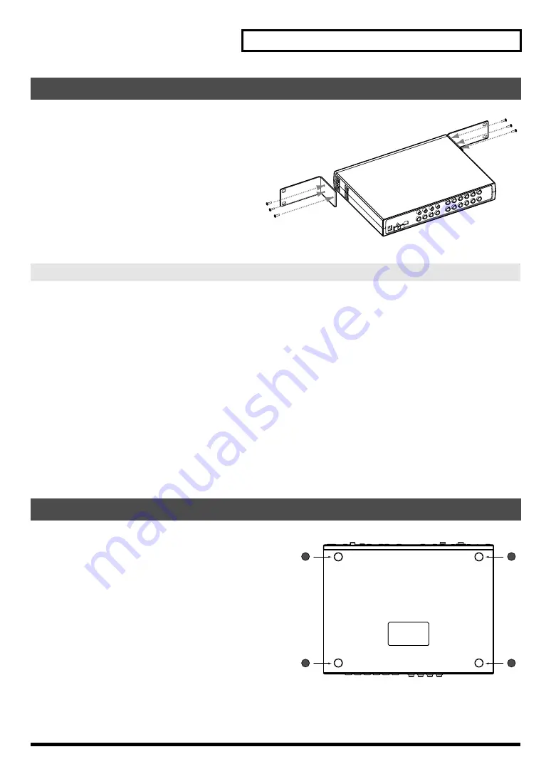
1.

Remove three screws (on each side) from 

the right and left panels of the I/O module.

2.

Using the screws you removed in step 1, 

attach the rack-mount brackets to the I/O 

module.

* You must use the screws that you removed. Do not use 

any other screws.

When you are mounting the unit on a rack or the like, give attention to the following points to ensure efficient 
cooling.

• Install in a well-ventilated location.

• Avoid mounting in a sealed rack. Warm air within the rack cannot escape and is sucked into the unit again, making 

efficient cooling impossible.

• When you are using a stacked mounting arrangement, be especially sure to provide for adequate ventilation within 

the rack to keep discharged air from being sucked back into the unit. If the back surface of the rack cannot be kept 
open, then provide a ventilation port or ventilation fan at the upper area of the back surface of the rack, where warm 
air accumulates.

• When you are using the unit in a portable case or rack, remove the covers from the front and back surfaces of the 

case, so that the front and back surfaces of the unit are not obstructed.

* When placing the unit on the rack, be careful not to pinch your fingers.

For more information about installation, also see “Placement” (p. 5).

Attach these as required, such as when you’re using the 

I/O module without mounting it on a rack or the like.

Peel off the double-sided tape from the rubber feet and 
affix the rubber feet at the locations shown in the 
following figure.

Attaching the rack-mount adaptor

Rack mounting (important notes on heat radiation)

Attaching the rubber feet

Summary of Contents for Edirol M-16DX

Page 1: ...of the unit Additionally in order to feel assured that you have gained a good grasp of every feature provided by your new unit Owner s manual should be read in its entirety The manual should be saved and kept on hand as a convenient reference Copyright 2007 ROLAND CORPORATION All rights reserved No part of this publication may be reproduced in any form without the written permission of ROLAND CORP...

Page 2: ...r Connect the equipment into an outlet on a circuit different from that to which the receiver is connected Consult the dealer or an experienced radio TV technician for help This device complies with Part 15 of the FCC Rules Operation is subject to the following two conditions 1 this device may not cause harmful interference and 2 this device must accept any interference received including interfer...

Page 3: ...u experience any hearing loss or ringing in the ears you should immediately stop using the unit and consult an audiologist 011 Do not allow any objects e g flammable material coins pins or liquids of any kind water soft drinks etc to penetrate the unit 012b Immediately turn the power off remove the AC adaptor from the outlet and request servicing by your retailer the nearest Roland Service Center ...

Page 4: ...s prongs Also disconnect the power plug from the power outlet whenever the unit is to remain unused for an extended period of time Any accumulation of dust between the power plug and the power outlet can result in poor insulation and lead to fire 104 Try to prevent cords and cables from becoming entangled Also all cords and cables should be placed so they are out of the reach of children 106 Never...

Page 5: ...in this condition Therefore before using the unit you must allow it to stand for several hours until the condensation has completely evaporated 360 Depending on the material and temperature of the surface on which you place the unit its rubber feet may discolor or mar the surface You can place a piece of felt or cloth under the rubber feet to prevent this from happening If you do so please make su...

Page 6: ...dangerous in the event of lightning Handling the CD ROMs 801 Avoid touching or scratching the shiny underside encoded surface of the disc Damaged or dirty CD ROM discs may not be read properly Keep your discs clean using a commercially available CD cleaner Copyright 852a This product can be used to record or duplicate audio or visual material without being limited by certain techno logical copy pr...

Page 7: ...in connections 21 Example 1 Home studio 22 Example 2 Simple PA 23 Example 3 Computer music 24 Turning the power on 25 Turning the power off 25 Basic operation 26 SOLO PRE FADER switches 27 MUTE ALT switches 27 SEL buttons 27 Using the M 16DX with your computer 28 What is a driver 28 Advanced use 29 Making detailed equalizer settings 29 Using the dedicated vocal narration effect Insert Effect 30 Ed...

Page 8: ...AC SOURCE 44 Changing the system settings UTILITY 44 Basic procedure 44 Adjusting the brightness of the screen LCD Contrast 45 Specifying the M 16DX s sampling frequency Sample Freq 45 Outputting the CONTROL ROOM jacks signal from ALT OUT jacks CTRL to ALT 45 Selecting the output to which Room Acoustic Control and Finalize will apply RAC FINALIZE 45 Specifying the frequency range analyzed by Room ...

Page 9: ... as narrations and announcements a finalize effect which improves the overall volume and loudness balance to create your final sound and FX which provides spatial type effects such as echo and reverb to simulate the acoustics of a club or hall The M 16DX s Room Acoustic Auto Control function analyzes the acoustical characteristics of the room and automatically adjusts the output signal so that it ...

Page 10: ...10 Block diagram ...

Page 11: ...11 ...

Page 12: ...is is set to NARROW you ll be able to make detailed adjustments When you turn the SENS knob it may seem as though the change does not occur smoothly but this is not a malfunction 3 EQ Knobs HI MID LOW Provide for three band equalization with high mid and low frequency controls for each channel The corresponding frequency range will be boosted when you turn a knob toward the right be cut when you t...

Page 13: ...u want to check the current AUX level of each channel fig 02 AUX1 bmp Press the DISPLAY button to return to the level meter screen 8 AUX 2 Button If you press this button so it s lit the AUX knobs will function in adjusting AUX 2 levels When the effect FX is on turning an AUX knob will simultaneously adjust the AUX 2 level as well as the effect depth of the channel The display will show the AUX 2 ...

Page 14: ... 13 14 11 13 12 14 15 On The signal of the channel will be sent to the ALT bus and muted for the MAIN bus Off The signal of the channel will be sent to the MAIN bus Button lit When you press the DIGITAL button the button will light if a valid digital signal is being input to DIGITAL IN jack connector and the signal from DIGITAL IN jack connector will be input to channels 11 12 Button blinking If n...

Page 15: ...n If you hold down this button for one second or longer so it s lit the signal after passing through the MAIN MIX LEVEL knob will no longer be output from the PHONES jack and CONTROL ROOM jacks When you press the button to turn off its illumination the signal after passing through the MAIN MIX LEVEL knob will once again be output from the PHONES jack and CONTROL ROOM jacks 23 AUX 1 MASTER Knob Adj...

Page 16: ...lizer Making detailed equalizer settings p 29 32 INSERT FX Button Press this when you want to edit the Insert Effect settings When you press the button it will light and the Insert Effect screen will appear Using the dedicated vocal narration effect Insert Effect p 30 33 FINALIZE Button Press this when you want to edit the Finalize settings When you press the button it will light and the Finalize ...

Page 17: ...are 1 4 phone jacks that output the same sound as the PHONES jack Connect to these if you re using nearfield powered monitors instead of headphones 41 LINE IN AUX RETURN 2 Jacks 15L 16R These are 1 4 phone line input jacks If you ve connected the AUX SEND 2 jacks to an external effects processor use these jacks to input the output signal from the external effects processor 42 LINE IN STEREO Jack 1...

Page 18: ...s you ve connected a condenser mic that requires a phantom power supply Supplying phantom power to a dynamic mic or an audio playback device will cause malfunctions For details on the specifications for your mic refer to the instruction manual that came with the mic you re using The M 16DX s phantom power per channel DC 48 V 5 mA Max You can specify whether phantom power will be supplied to all MI...

Page 19: ...t the signals output by the external effects processor to 13L and 14R If you ve connected the AUX SEND 2 jacks to an external effects processor input the signals output by the external effects processor to 15L and 16R 13 2 TRACK OUT Jacks L R You can connect these RCA pin type output jacks to a cassette deck or other recording device 14 ALT OUT Jacks L R These are balanced TRS 1 4 output jacks tha...

Page 20: ... route for signals sent from the MAIN bus ALT OUT This is the output route for signals sent from the ALT bus You can also send these signals to the MAIN bus by making the appropriate setting on the mix controller AUX SEND This is the output route for signals sent from the AUX bus PHONES CONTROL ROOM This is the output route used to monitor the signals of MAIN OUT and ALT OUT By making the appropri...

Page 21: ...ected Here we will explain how to connect the M 16DX to speakers mics audio equipment and a computer To prevent malfunction and or speaker damage you must turn down the volume on all equipment and switch off their power before making connections Secure the cord from the AC adaptor by looping it around the cord hook as shown in the illustration This will prevent the cord from being unplugged even i...

Page 22: ...ge a system setting p 45 so that phantom power is supplied only to channels 3 and 4 3 If you ve digitally connected a device to the DIGITAL IN jack turn the DIGITAL button on lit You ll need to match the sampling frequency of the connected device and the M 16DX p 45 4 The audio signals from your computer are input to channels 13 14 Press the USB button so it s lit Example 1 Home studio 1 2 3 4 Com...

Page 23: ... If you ve connected a dynamic mic turn the PHANTOM switch off Example 2 Simple PA Portable recorder Portable audio player 1 2 Computer Multiple effects Keyboard 1 Keyboard 2 Guitar with Multiple effects Direct Box Rhythm machine DIGITAL OUT Stereo headphones 18 IN Included AC adaptor Power amp Guitar amp Bass amp Dynamic mic for vocals Electric acoustic guitar Bass guitar Monitor speaker Power am...

Page 24: ...nd 2 do not require phantom power Change the system settings p 45 so that phantom power is supplied only to channels 3 and 4 3 If you ve digitally connected a device to the DIGITAL IN jack turn the DIGITAL button on lit You ll need to match the sampling frequency of the connected device and the M 16DX p 45 4 The audio signals from your computer are input to channels 13 14 Press the USB button so i...

Page 25: ...h on the power to your analog connected equipment musical instruments sound modules effects processors mics CD players etc 5 Turn on the M 16DX s POWER switch I O module The POWER indicator will light After the power is turned on the display will show the level meter screen fig 03 Setup 6 Switch on the power to your amp and powered monitors 1 Make sure you ve done the following before you turn off...

Page 26: ...alance 5 Use the EQ knobs to adjust the high mid and low frequency ranges When you turn these knobs the equalizer screen will appear in the display showing the current settings numerically and graphically fig 03 EQ e You can change the center frequency of the high mid and low ranges and also change the width of the mid range band MID Q Making detailed equalizer settings p 29 6 When you ve finished...

Page 27: ...ll be highlighted in the level meter screen fig 02 MUTE ALT If you press this button lit the parameter screen of the selected channel will appear in the display This button can be pressed at any time to toggle between the parameter screen and the equalizer screen The screen will show the current settings of the selected channel In this screen you can edit the settings while watching the numerical ...

Page 28: ...hannels of signals to be sent to your computer If the M 16DX is connected to your computer when operating at the 24 bit 96 Hz setting you won t be able to use Finalize p 41 fig Driver e The driver is software that passes data between the M 16DX and the application software running on your computer when the M 16DX is connected via a USB cable The driver sends data from the application software to t...

Page 29: ...the CURSOR BWD FWD buttons to select the parameter you want to edit The selected parameter is highlighted 3 Use the VALUE buttons to edit the value Making detailed equalizer settings Parameter Description H Center frequency of the high range M Center frequency of the mid range L Center frequency of the low range MIDQ Width of the mid frequency range When the equalizer screen is displayed you can u...

Page 30: ...Selecting an effect type fig INSFX 01 2 Use the CURSOR BWD FWD buttons to move the cursor to the effect type 3 Use the VALUE buttons to select an effect type Editing the parameters fig INSFX 03 4 Use the CURSOR BWD FWD buttons to move the cursor to the parameter you want to edit 5 Use the VALUE buttons to edit the value If you press the button while holding down the button or press the button whil...

Page 31: ...voice may be less intelligible Power Cmp1 BASS 0 100 Mainly adjusts the loudness of the low frequency range Raising this setting will boost the low frequency range Power Cmp2 TONE 0 100 Mainly adjusts the loudness of the mid frequency range Raising this setting will boost the mid frequency range Power Cmp3 BRIGHT 0 100 Mainly adjusts the loudness of the high frequency range Raising this setting wi...

Page 32: ...g attack and end decay of the voice may be cut off unnaturally or the voice may be less intelligible TONE 0 100 Boosts the frequency range that is the basic component of the voice Raise this value to make the vocal more rich sounding or lower it to re duce unwanted resonance or loudness BRIGHT 0 100 Increases the brightness The higher the value the brighter the sound Parameter Range Explanation NS...

Page 33: ...ton when the FX screen is already displayed the effect will be turned off and the button s light will go out Selecting the effect type fig FX 01 2 Use the CURSOR BWD FWD buttons to move the cursor to the effect type 3 Use the VALUE buttons to select the effect type Editing the parameters fig FX 03 4 Use the CURSOR BWD FWD buttons to move the cursor to the parameter you want to edit 5 Use the VALUE...

Page 34: ... of the repetitions DAMP 315 8k Hz BYP Specifies the frequency at which the repeated sound will begin to be attenuated With the BYP setting the repeated sound will not be attenuated Parameter Range Explanation P DLY 0 0 160 ms Adjusts the time at which the reverberation starts being heard TIME 0 0 6 0 s Adjusts the length time of reverberation DAMP 315 8k Hz BYP Specifies the frequency at which th...

Page 35: ... jacks Selecting the output to which Room Acoustic Control and Finalize will apply RAC FINALIZE p 45 You can specify the upper and lower limits of the frequencies that will be automatically adjusted Specifying the frequency range analyzed by Room Acoustic Auto Control RAC Freq RAC Freq p 45 Adjusting the output signal appropriately for your environment Room Acoustic Control Automatic adjustment Ro...

Page 36: ...uttons to select the response curve that will be the index for the adjustment You can create four variations for each frequency response curve With the factory settings 1 4 all have the same settings You can adjust the amplitude of the curves as suitable for different uses FLAT 1 4 Flat response BUMPY 1 4 Response curves that boost the low and high frequency regions producing the so called scooped...

Page 37: ...he screen will indicate Measuring and analysis of the L channel will start automatically If you decide to cancel the operation press the DISPLAY EXIT button Range 70 100 130 If the screen does not indicate Measuring i e if the test signal cannot be detected check or adjust the following settings Could the MAIN MIX LEVEL knob be set too low Ideally the knob should be set near the U position Could t...

Page 38: ...e been completed for both channels the ROOM ACOUSTIC AUTO CONTROL button and 16 BAND GRAPHIC EQ button will change from blinking to lit and the screen will show the result of the adjustment When the adjustment has been completed the input channels will be unmuted and the M 16DX will return to normal operation 8 Listen to the adjusted sound The frequency response curve and its amplitude is stored t...

Page 39: ...own in the left of the screen fig RAC 16 When you press the ROOM ACOUSTIC AUTO CONTROL button so it s lit and turn the Room Acoustic Control function on the 16 BAND GRAPHIC EQ button will also light the most recently selected settings will be called up At this point use the CURSOR BWD FWD buttons to move the cursor to the frequency response curve and use the VALUE buttons to switch curves the ampl...

Page 40: ...most recently assigned graphic equalizer state will be called up fig GEQ 02 If you press the 16 BAND GRAPHIC EQ button while the equalizer screen is displayed the graphic equalizer will be turned off and the button s light will go out fig GEQ 03 2 Use the FREQ knob to select a frequency 3 Turn the GAIN knob to adjust the level of that frequency The selected frequency and its level are shown in the...

Page 41: ...g the effect on The Finalize screen will appear If a different screen is displayed even though the FINALIZE button is lit you can press the FINALIZE button to access the Finalize screen fig FINAL 02 If you press the FINALIZE button when the Finalize screen is already displayed the effect will turn off and the button s light will go out Selecting an effect type fig FINAL 01 2 Use the CURSOR BWD FWD...

Page 42: ...ously increases the volume This will thicken the sound of the low frequency range Increasing this value will set this to a high er level Unlike simply raising the volume this produces a thicker and denser low frequency range H COMPRESS 0 100 Lowers the high frequency threshold for the multi band compressor and simultaneously increases the volume This will thicken the sound of the high frequency ra...

Page 43: ...be higher than the current setting Use this function with caution and be aware of the volume of your speakers or headphones If the SCENE button is lit only the settings of the called up scene are valid Panel operations won t be reflected in the sound If you operate the panel knobs or other controls a message will appear in the screen fig SCENE 04 By holding down the DISPLAY button and turning the ...

Page 44: ...n the channel 1 EQ knobs or press the SEL button the following message will appear fig Func CH1 Caution You can change various system settings in order to perform mixing operations more conveniently and efficiently You can also restore the settings of the M 16DX to their original state 1 Press the CURSOR BWD and FWD buttons simultaneously The Utility screen will appear fig UTIL 01 2 Use the CURSOR...

Page 45: ...If the function switch is set to INT use the following settings RAC Freq 40 Hz RAC Freq 16 kHz You can specify the channels 1 4 to which phantom power will be supplied Adjusting the brightness of the screen LCD Contrast Range 0 19 Specifying the M 16DX s sampling frequency Sample Freq Settings 44 1 48 96 kHz Outputting the CONTROL ROOM jacks signal from ALT OUT jacks CTRL to ALT Setting Explanatio...

Page 46: ...DISPLAY EXIT button When initialization is finished the display will indicate COMPLETE This operation will restore all settings including the UTILITY settings to their factory set state This is called Factory Reset 1 Turn the power off 2 While holding down the FINALIZE button and ROOM ACOUSTIC AUTO CONTROL button press the POWER switch to turn the power on The screen will indicate Factory Reset an...

Page 47: ... EQ knobs HI MID LO of each channel to re adjust the equalizer levels Is there a problem with the level indications in the level meter If the sound is crackly or distorted even though there is no problem with the level indications in the level meter the output volume is appropriate but the input volume is too high Please adjust the M 16DX s input volume level Basic use p 21 Are the insert effect f...

Page 48: ... other equipment connected This noise is called hum The M 16DX and the connected equipment may pick up electromagnetic interference and emit this noise as a result This noise can be caused by the power supply frequency 50 60 Hz or by high output motors Try moving your equipment away from the device that contains a motor or connecting the M 16DX to a different AC outlet You can also try connecting ...

Page 49: ... to 48 kHz or disconnect the USB connection Could you be using a connection cable that contains a built in resistor Use a connection cable that does not contain a built in resistor Could you have connected a condenser mic that requires phantom power If you re connecting a condenser mic that requires phantom power turn the PHANTOM switch on With the default settings phantom power is supplied to all...

Page 50: ... driver p 52 and then install the M 16DX driver once again as described in Driver installation and settings Could you have connected the M 16DX to a USB connector that s different than the one used when you installed the driver The USB driver must be installed for each USB connector to which you connect the M 16DX If you have a USB hub or a computer that has more than one USB connector you should ...

Page 51: ...click Properties The Advanced Power Management Support Properties dialog box will appear 5 Click the Settings tab and in Troubleshooting check the Don t Poll Power Supply Status check box Then click OK 6 In the System Properties dialog box click OK 7 Restart Windows Are you using a USB device in addition to the M 16DX Try switching off USB audio devices other than the M 16DX You may be able to sol...

Page 52: ... updated Windows XP If you have not updated Windows XP a heavy processing load will be placed on the CPU when recording or playing back audio and the system will not operate correctly Please update to Windows XP SP2 If you were unable to install the USB driver using the procedure given it is possible that your computer did not recognize the M 16DX s USB driver correctly In this case you ll need to...

Page 53: ... 20 kΩ LINE IN jacks 15 16 Stereo miniature phone type 14 kΩ Nominal Output Level MAIN OUT jacks ALT OUT jacks AUX SEND jacks 1 2 0 dBu 2 TRACK OUT jacks L R 10 dBu CONTROL ROOM jacks 6 dBu Maximum output level Nominal Output Level 22 dB Output Impedance MAIN OUT jacks ALT OUT jacks AUX SEND jacks 1 2 600 Ω 2 TRACK OUT jacks L R 1 kΩ Recommended Load Impedance 10 kΩ or greater Display Graphic LCD ...

Page 54: ...ll reverb Large hall reverb Number of USB Audio Record Playback Channels Record 18 channels Playback 2 channels Full duplex When using the mixer as a USB audio interface the Finalize effects are not available in 96 kHz mode Power Supply DC 9 V AC adaptor Current Draw 1 4 A Phantom Power 48 V 5 mA each input Dimensions I O module 280 0 W x 219 0 D x 44 0 H mm 11 1 16 W x 8 5 8 D x 1 3 4 H inches MI...

Page 55: ...ep discharged air from being sucked back into the unit If the back surface of the rack cannot be kept open then provide a ventilation port or ventilation fan at the upper area of the back surface of the rack where warm air accumulates When you are using the unit in a portable case or rack remove the covers from the front and back surfaces of the case so that the front and back surfaces of the unit...

Page 56: ...ROOM 17 Cord Hook 19 21 COSM 30 CROSS 42 Cross 42 CTRL 45 CTRL to ALT 45 CURSOR 16 D DAMP 34 DC IN 19 DEESSER 32 DELY 34 DIGITAL 14 DIGITAL IN 18 DIGITAL OUT 19 DISPLAY 17 Display 16 Driver 28 50 52 DX BUS 17 19 E ECHO 34 Echo 15 33 ENTER 46 EQ 12 26 EXIT 46 EXT 44 F Factory Reset 46 FAT Comp 42 Final 42 FINALIZE 16 41 Finalize 41 46 FLAT 36 FREQ 16 39 40 Function Switch 17 44 FWD 16 FX 15 33 46 F...

Page 57: ...NES CTRL ROOM 15 25 POWER 19 25 Power Cmp1 31 Power Cmp2 31 Power Cmp3 31 PRE 15 PRE FADER 13 27 R RAC 44 RAC FINALIZE 45 RAC Freq 45 RAC Freq 45 RAC SOURCE 44 REGULAR 44 REPT 34 Reverb 15 33 ROOM 34 ROOM ACOUSTIC AUTO CONTROL 16 36 39 Room Acoustic Auto Control 35 Room Acoustic Control 35 44 ROOM ACOUSTIC SENSOR 17 S Sample Freq 45 SCENE 17 43 Scene 43 46 SEL 13 27 SENS 12 26 SENS RANGE 44 SHORT ...

Page 58: ...58 For EU Countries GR SK CZ SI LV LT EE PL HU FI SE NO DK NL PT ES IT DE FR UK ...

Page 59: ...le Principal de la Farmacia 5ta Avenida 1 Cuadra al Lago 503 Managua Nicaragua TEL 505 277 2557 PERU Audionet Distribuciones Musicales SAC Juan Fanning 530 Miraflores Lima Peru TEL 511 4461388 IRELAND Roland Ireland G2 Calmount Park Calmount Avenue Dublin 12 Republic of IRELAND TEL 01 4294444 ITALY Roland Italy S p A Viale delle Industrie 8 20020 Arese Milano ITALY TEL 02 937 78300 NORWAY Roland S...

Page 60: ...04561878 2MP ...

Reviews: