
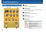


Panel Descriptions
4
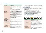
Parameter
Explanation
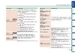
BOOST
TYPE
(BOOSTER TYPE)
XDS
(X-DIST)
:
This is a distortion that
uses MDP to obtain the distortion
that’s most appropriate in each pitch
range.
STK
(STACK DRIVE)
:
This models the
sound of the BOSS ST-2.
FAT
(FAT DIST)
:
A distortion sound with
thick distortion.
MZN
(METAL ZONE)
:
This models the
sound of the BOSS MT-2.
MCR
(METAL CORE)
:
This models the
sound of the BOSS ML-2.
FUZ
(FUZZ)
:
This models an Electro-
Harmonix Big Muff π.
BOOST
PRE
(BOOSTER PRE GAIN)
Adjusts the gain of the booster.
BOOST
POST
(BOOSTER POST GAIN)
Adjusts the volume when boost is on.
GATE
DECAY
Adjusts the time until the gate closes.
With smaller values, the gate closes
faster.
GATE
THRESH
(GATE THRESHOLD)
Adjusts the volume at which the gate
applies.
With larger values, the gate applies at
a higher volume.
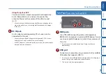
You can also select a parameter or memory by pressing
the [PARAM] knob.
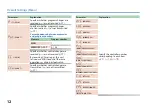
About the booster
As its main distortion, the OD-200 provides 12 different
types of sound.
The position of the booster connection and the
operations of the BOOSTER PRE GAIN, BOOSTER
POST GAIN, and LOW/MIDDLE/HIGH knobs will differ
depending on the STRUCTURE parameter.
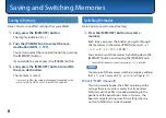
When STRUCTURE is SERIES
The booster is placed before the main distortion.
Guitar
&
Booster
Pre GAIN
&
Main
distortion
&
Booster
Post GAIN
&
Gate
&
Amp
Parameter
Explanation
BOOST
PRE
(BOOSTER PRE GAIN)
Adjusts the booster gain.
Increasing this value increases the
signal that is input to the main
distortion, making the distortion
stronger. The distortion of the booster
itself does not change.
BOOST
POST
(BOOSTER POST GAIN)
Adjusts the volume when boost is on.
This let you raise (or lower) the
volume when using the booster to
increase the gain when transitioning
from backing to solo.
Summary of Contents for BOSS OD-200
Page 18: ......