


Putting the Analyzer into Operation
R&S
®
ZND
14
Getting Started 1316.2407.02 ─ 52
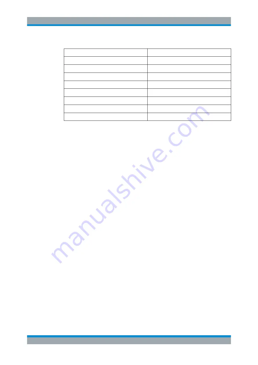
Table 3-1: Cable Requirements
Cable Type (Connector)
Requirement
RF cables (PORT 1, ..., PORT N)
Double shielded
BNC cables (various)
Double shielded
DB-25 (USER PORT)
Double shielded
GPIB
Standard cable
Handler I/O
Standard cable
DVI-D (Monitor)
2 ferrite cores
LAN
At least CAT6, S/FTP
USB
Standard cables, length ≤ 3m
3.6
Connecting the Analyzer to the AC Supply
The network analyzer is automatically adapted to the AC supply voltage, which must
be in the range of 100 V to 240 V at 50 Hz to 60 Hz. The mains connector is located in
the upper part of the rear panel (see
► Connect the network analyzer to the AC power source using the AC power cable
delivered with the instrument.
The maximum power consumption and the typical power consumption of the individual
analyzer models are listed in the data sheet.
3.7
Starting the Analyzer and Shutting Down
The AC power switch is located in the upper part of the rear panel, together with the
mains connector; see
To start the analyzer, proceed as follows:
1. Switch the AC power switch to position
I
(On).
After power-on, the analyzer automatically goes to standby or ready state, depend-
ing on the state of the standby toggle key at the front panel when the instrument
was switched off last time.
2. If necessary, press the standby toggle key on the front panel to switch the instru-
ment to ready state (the green LED goes on).
The instrument automatically performs a system check, boots the Windows
®
oper-
ating system and then starts the vector network analyzer (VNA) application. If it
was terminated regularly, the VNA application restores all recall sets and instru-
ment settings of the previous analyzer session.
Starting the Analyzer and Shutting Down


