background image

Interference Analyzer

R&S

®

Spectrum Rider FPH

247

User Manual 1321.1011.02 ─ 06.00

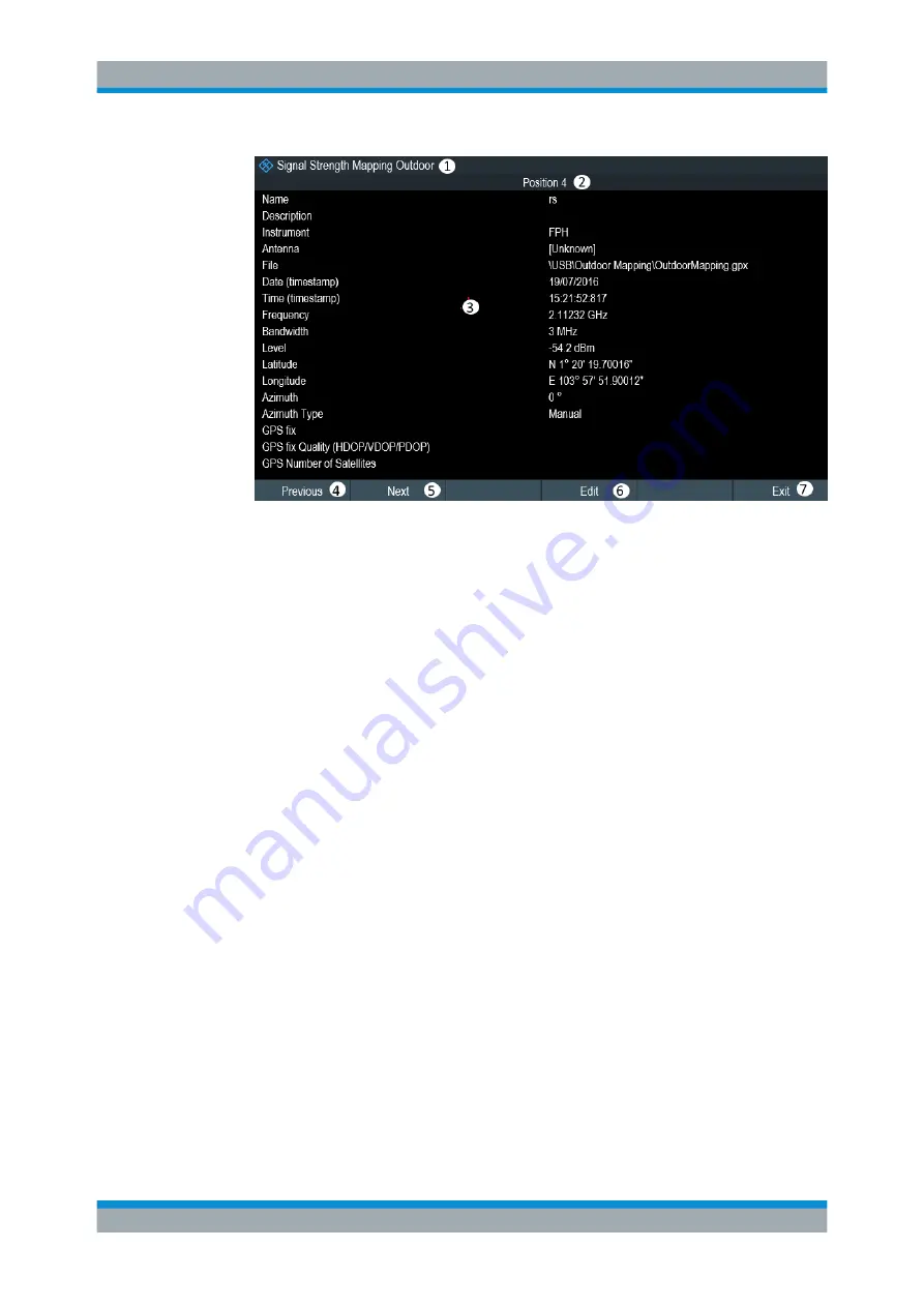
Figure 11-6: Complete geotag information dialog box

1 = Outdoor mapping measurement mode
2 = Item number in the GPS position list
3 = Complete information of the selected geotag
4 = Select "Previous" softkey to view the previous item number in the GPS position list
5 = Select "Next" softkey to view the next item number in the GPS position list
6 = Select "Edit" softkey to edit the "Name" and "Description" of the geotag information
7 = Select "Exit" softkey to quit from the view

The R&S Spectrum Rider allows you to change the name and description anytime you

want. All other geotag information is unchangeable after it has been saved.

1. Select "Edit" softkey.

The R&S Spectrum Rider opens a dialog box to change the geotag information.
Note: Only the "Name" and "Description" field are editable in the dialog box, all
other information saved are locked.

Working with Maps

Summary of Contents for R&S FPH

Page 1: ...Spectrum Rider FPH Handheld Spectrum Analyzer User Manual User Manual Version 06 00 1321101102 E 2...

Page 2: ...1 55 or higher The software contained in this product uses several valuable open source software packages For information see the Open Source Acknowledgment document which is available for download fr...

Page 3: ...e of the product The product is used for its designated purpose if it is used in accordance with its product documentation and within its performance limits see data sheet documentation the following...

Page 4: ...ation item 7 Signal words and their meaning The following signal words are used in the product documentation in order to warn the reader about risks and dangers Indicates a hazardous situation which i...

Page 5: ...afety is not observed either at all or to the extent necessary electric shock fire and or serious personal injury or death may occur 1 Prior to switching on the product always ensure that the nominal...

Page 6: ...t be fuse protected in such a way that anyone who has access to the product as well as the product itself is adequately protected from injury or damage 14 Use suitable overvoltage protection to ensure...

Page 7: ...masks and protective clothing must be worn 7 Laser products are given warning labels that are standardized according to their laser class Lasers can cause biological harm due to the properties of the...

Page 8: ...ckaging until they are ready to be used 4 Cells and batteries must not be exposed to any mechanical shocks that are stronger than permitted 5 If a cell develops a leak the fluid must not be allowed to...

Page 9: ...e the batteries See the device manual or data sheet for the exact designation of the charger If the batteries are improperly charged there is a risk of explosion which can cause serious personal injur...

Page 10: ...ng the Instrument 22 3 1 1 2 Accessory List 23 3 1 1 3 Setting up the R S Spectrum Rider 23 3 1 1 4 Using the AC Adapter 25 3 1 1 5 Battery Operation 26 3 1 1 6 Battery Maintenance 27 3 1 2 Switching...

Page 11: ...3 Managing Options with R S License Manager 50 3 2 7 Configuring the R S Spectrum Rider 52 3 2 7 1 Configuring the Hardware 52 3 2 7 2 Configuring Antennas 53 3 2 7 3 Using the GPS Receiver 57 3 2 7...

Page 12: ...cy 88 4 2 2 Change Reference Level 89 4 2 3 Change Span 90 4 2 4 Add Marker 90 4 2 5 Move Marker 91 4 2 6 Delete All Markers 92 4 2 7 Hide or Unhide Measurement Result View Display 92 4 2 8 Preview Sc...

Page 13: ...or Power Display 121 6 1 3 Measuring the Occupied Bandwidth 121 6 1 3 1 Selecting a Standard 122 6 1 3 2 Setting the Reference Level 123 6 1 3 3 Setting the Channel Bandwidth 124 6 1 3 4 Defining the...

Page 14: ...Update 145 6 1 9 2 Browsing through the Signal History 146 6 1 9 3 Configuring the Display 147 6 1 9 4 Recording a Spectrogram 151 6 1 9 5 Playback of a Spectrogram 155 6 1 10 Using Isotropic Antenna...

Page 15: ...Trace 180 6 2 6 4 Working with Memory Traces 181 6 2 6 5 Using Trace Mathematics 182 6 2 7 Using Markers 182 6 2 7 1 Using Markers and Deltamarkers 182 6 2 7 2 Positioning Markers 183 6 2 7 3 Position...

Page 16: ...ing Pulse Characteristics 216 9 2 2 Selecting the Video Bandwidth 217 9 2 3 Averaging Traces 217 9 2 4 Triggering Measurements 218 9 2 5 Selecting the Result Unit 219 9 2 6 Scaling the Y Axis 219 9 2...

Page 17: ...11 3 5 2 Triangulation 248 11 3 5 3 Indoor Mapping 250 11 3 6 Analyzing Geographic Data 253 11 3 7 Analyzing Indoor Data 254 12 Receiver Mode 256 12 1 Selecting the Measurement Mode 256 12 1 1 Perfor...

Page 18: ...4 SCPI Command Structure and Syntax 274 13 4 1 Structure of a Command 274 13 4 1 1 Common Commands 274 13 4 1 2 Device Specific Commands 275 13 4 1 3 Overview of Syntax Elements 278 13 4 2 Parameters...

Page 19: ...the Measurement Mode 360 13 6 3 8 Reading out Measurement Results 361 13 6 4 Remote Commands of the Power Meter 364 13 6 4 1 Setting the Frequency 364 13 6 4 2 Configuring Power Level Readout 365 13 6...

Page 20: ...Status Byte STB Service Request Enable Register SRE 404 13 6 11 4 Event Status Register ESR and Event Status Enable Register ESE 405 13 6 11 5 Application of the Status Reporting Systems 408 13 6 11 6...

Page 21: ...Parameters 446 14 4 3 BW Parameters 446 14 4 4 Amplitude Parameters 447 14 4 5 Sweep Configuration 447 14 4 6 Limits Line Parameters 447 14 5 Functions of the Wizard 448 14 5 1 Measurement Wizard 448...

Page 22: ...R S Spectrum Rider FPH 15 User Manual 1321 1011 02 06 00 14 7 6 Trace Functionality 462 14 7 7 Limits Line Parameters 462 15 Appendix 464 15 1 How a Spectrum Analyzer Works 464 List of Commands 469 I...

Page 23: ...cription of all fea tures of the InstrumentView software package Service manual Describes the performance test for checking the rated specifications module replace ment and repair firmware update trou...

Page 24: ...panel 1 2 Conventions Used in the Documentation The following conventions are used throughout the R S Spectrum Rider manual 1 2 1 Typographical Conventions The following text markers are used througho...

Page 25: ...ription of such commands all parts that have to be entered are written in capital letters Addi tional text in lower case characters is for information only Conventions Used in the Documentation 2 Welc...

Page 26: ...must be used in an appropriate manner to prevent electric shock fire personal injury or damage Do not open the instrument casing Read and observe the Basic Safety Instructions delivered as a printed b...

Page 27: ...no sign of condensation The instrument is positioned as described in the following sections The ambient temperature does not exceed the range specified in the data sheet Signal levels at the input co...

Page 28: ...tation Packing material Retain the original packing material If the instrument needs to be transported or ship ped at a later date you can use the material to protect the control elements and con nect...

Page 29: ...ut the support on the back of the R S Spectrum Rider Before you turn on the R S Spectrum Rider you should insert the lithium ion battery included in the delivery into the battery compartment located a...

Page 30: ...the AC adapter to the DC port on the left side of the R S Spectrum Rider item 1 of Figure 3 1 Make sure to fully insert the AC adapter plug into the DC port Depending on the system you need firmly con...

Page 31: ...ging current is reduced as the power is partially drained by the usage of the R S Spectrum Rider During operation in the field you can also charge the battery with the car adapter R S HA Z302 order nu...

Page 32: ...ons and in the following chapters Handling The battery has been designed for a specific application Do not use it for any other applications Do not connect batteries in series or parallel as it can ca...

Page 33: ...t every six months Should the battery voltage be low or even 0 V the battery protection circuit may have gone into a sleep mode In that case reset the battery with an approved charger Transportation N...

Page 34: ...e battery charging is in process Amber LED Instrument is in switch off mode with AC supply and there is no bat tery in it Red LED There is an error in the battery charging LED OFF This is an indicatio...

Page 35: ...s indicated in the delivery note 4 Check the availability of the hardware options as indicated in the delivery note 5 Press the HW SW Info softkey A list with hardware and firmware information is disp...

Page 36: ...l Keys 45 Managing Options 49 Configuring the R S Spectrum Rider 52 Connecting the R S Spectrum Rider to a PC 67 3 2 1 Overview Control Figure 3 4 Front panel of R S Spectrum Rider 1 RF input N connec...

Page 37: ...de of the instrument can be cleaned sufficiently using a soft lintfree dust cloth 3 2 2 Connectors of the R S Spectrum Rider The R S Spectrum Rider has several connectors The connectors are either on...

Page 38: ...d damage to the coupling capacitor input attenuator or the mixer the DC input voltage must never exceed the value specified in the data sheet 3 2 2 2 BNC Connector The BNC connector is located on the...

Page 39: ...ector on page 53 and Chapter 3 2 7 3 Using the GPS Receiver on page 57 3 2 2 3 Headphone Jack The 3 5 mm connector for headphones is located on the top of the R S Spectrum Rider The internal impedance...

Page 40: ...charge the battery 3 2 2 6 Mechanical Locking Device The Kensington lock is located behind a protective cap on the left side of the R S Spectrum Rider A Kensington lock can be anchored to the R S Spe...

Page 41: ...g the Hardware on page 52 3 2 2 8 SD Card Slot The SD card slot is located behind the battery compartment of the R S Spectrum Rider Peel open the SD card protective cap to access to the SD card slot Y...

Page 42: ...ver touch the screen with ball point pens or other pointed objects with sharp edges It is recommended that you operate the touchscreen by finger only As an alterna tive you may use a stylus pen with a...

Page 43: ...ment Result View to hide or unhide the measurement result view display In the file manager dialog swipe horizontally to the left or right direction to preview screenshots In the wizard measurement mod...

Page 44: ...on measurement result is displayed in the Measurement result view e g Frequency Count The selected marker is highlighted in the Measurement result view it is also reflected on the marker in the Measur...

Page 45: ...ated at the right side and bottom section of the layout See Figure 3 5 You can select any parameter in the Parameter view to adjust the configurations of the spectrum measurement See details of each o...

Page 46: ...4 Configuring Date and Time on page 59 REF Select REF to display an entry box to configure the reference level for the spectrum measurement ATT Select ATT to display an entry box to configure the att...

Page 47: ...he Parameter View it is operation mode dependent See Figure 3 5 When you select this button it opens the Config Overview window Accessing it with out the touchscreen input is possible via the SETUP ke...

Page 48: ...so provides configuration to set the transducer table used in the signal measurement Note When the optional pream plifier R S FPH B22 is absent the menu item RF Preamplifier is not available Select Fr...

Page 49: ...trigger source trigger level and the trigger delay setting on the spectrum measurement 3 2 4 On screen Keyboard The on screen keyboard is an additional means of interacting with the instrument It prov...

Page 50: ...screenshot of the current screen at anytime For more information see the R S Spectrum Rider user manual 3 2 5 3 Softkey The six softkeys on the front panel are used to access the softkey label See Ch...

Page 51: ...ling of result and instrument settings 3 2 5 5 Function Keys Function keys provide access to the most common measurement settings and func tions in the instrument A detailed description of the corresp...

Page 52: ...n Mask Measurement of multicarrier adjacent channel power Ch Power ACLR Harmonics distortion AM modulation depth AM Mod Depth Spectrogram Spectrogram Playback Isotropic Antenna MARKER Sets and positio...

Page 53: ...act like an enter key function CANCEL key Closes all kinds of dialog boxes if the edit mode is not active Quits the edit mode if the edit mode is active In dialog boxes that contain a Cancel button i...

Page 54: ...irmware options 3 2 6 1 Enabling Options To enable options you have to enter a key code The key code is based on the unique serial number of the R S Spectrum Rider 1 Press the SETUP key 2 Select the I...

Page 55: ...Rider 3 2 6 3 Managing Options with R S License Manager If you are using the R S Spectrum Rider in a local area network LAN you can man age the firmware options with a web browser e g Microsoft Inter...

Page 56: ...er one of the options If you already have one or more R S Spectrum Rider equipped with options you can manage the licenses of these options on the license manager web page 2 Select the button The brow...

Page 57: ...p contains an extensive description of all functionality that the license manager features 3 2 7 Configuring the R S Spectrum Rider In the Instrument Setup dialog box the R S Spectrum Rider provides v...

Page 58: ...drop down menu to select the BNC connector application opens 2 Select the required application 3 2 7 2 Configuring Antennas You can use the log periodic antenna R S HL300 order number 4097 3005 02 ac...

Page 59: ...ed antenna Note The Auto Accessory Detection menu item in the Hardware section turns off when an antenna is selected Enabling the compass The antennas feature an electronic compass to determine direct...

Page 60: ...the Instrument Setup dialog box select the Assign Antenna Switch menu item A drop down menu to select the function of the antenna toggle switch opens a Preamplifier Using the toggle switch turns the...

Page 61: ...ntenna information 2 Select YES softkey The R S Spectrum Rider tries to determine the antenna characteristics It shows the results in a dialog box 3 Select the Calibrate softkey The R S Spectrum Rider...

Page 62: ...S Spectrum Rider displays a Calibration Suc cessful message The R S Spectrum Rider displays the calibration result 3 2 7 3 Using the GPS Receiver The R S Spectrum Rider can locate your exact position...

Page 63: ...rovides all settings necessary to configure the GPS receiver Enabling the GPS receiver 1 In the Instrument Setup dialog box select the GPS item A drop down menu opens to turn the GPS receiver on or of...

Page 64: ...ws indicates that the GPS receiver is enabled and that there is a fix connection with enough satellites for the GPS receiver to provide the coordinates indicates that the GPS receiver is enabled but t...

Page 65: ...ntered the time the R S Spectrum Rider verifies the validity of the time If it is not a valid time it sets to the next valid time Selecting the time zone 1 In the Instrument Setup dialog box select th...

Page 66: ...select the language 2 Select one of the languages from the drop down menu 3 Reboot the device to activate the choice of selected language Setting the date format The R S Spectrum Rider provides two di...

Page 67: ...of the keyboard backlight is adjustable with a time delay setting to turn off the backlight The keyboard backlight remains on until the time specified by the Key board Backlight Delay or a subsequent...

Page 68: ...he keyboard backlight delay 1 In the Instrument Setup dialog box select the Display Backlight item 2 Enter the time you want to turn off the keyboard backlight with the numeric keys The time delay has...

Page 69: ...the volume of the system beeper of the R S Spec trum Rider used i e if a message box pops up 1 In the Instrument Setup dialog box select the System Beeper Volume item 2 Enter the volume you want with...

Page 70: ...t be used up soon When the battery low level is reached the battery symbol in the Title bar turns red and starts blinking See Chapter 3 1 1 5 Battery Operation on page 26 1 In the Instrument Setup dia...

Page 71: ...ed measurement parameter without using parameters from a previous mea surement unintentionally still being active Press the PRESET key Resetting the R S Spectrum Rider A Reset to Factory Settings rese...

Page 72: ...B port You have to install the R S InstrumentView software on the PC before you are able to establish a connection 1 Run the CD ROM delivered with the R S Spectrum Rider 2 Navigate to the Software sec...

Page 73: ...ct the DHCP item A drop down menu opens to select the DHCP state 2 Select DHCP to on or off as required Setting an IP address and subnet mask To establish a connection the PC and the R S Spectrum Ride...

Page 74: ...ss for PC 192 168 1 10 IP address for R S Spectrum Rider 192 168 1 20 IP address 1 Identify the IP address of your PC i e in the Microsoft Windows TCP IP Proper ties 2 In the Instrument Settings dialo...

Page 75: ...button to create a new network connection 4 Specify a name for the new network connection e g R S Spectrum Rider 5 Enter the IP address for the R S Spectrum Rider in this case 192 168 1 20 6 Confirm t...

Page 76: ...n Chapter 3 2 8 1 LAN Connection on page 67 After setting up the R S Spectrum Rider configure the R S InstrumentView software with the assigned IP address as described in Configuring the R S Instrumen...

Page 77: ...Connection Alternatively you can connect the R S Spectrum Rider to the PC with a USB cable The mini USB interface is located behind a protective cap on the right side of the R S Spectrum Rider When yo...

Page 78: ...1 Using the Spectrum Analyzer This chapter provides a short overview of the first steps of the measurements you can perform with the R S Spectrum Rider 3 3 1 1 Attenuating the Signal You can attenuat...

Page 79: ...ed with a blue dot in the menu item You can also set the attenuation manually TheR S Spectrum Rider provides attenuation in the range from 0 dB to 40 dB in 5 dB steps 4 Press the AMPT key 5 Select the...

Page 80: ...e preamplifier is switched on 1 Press the AMPT key 2 Select the Att Amp Imp softkey 3 Enable or disable the Preamp checkbox to turn on or off the preamplifier of the R S Spectrum Rider The magnitude o...

Page 81: ...w The R S Spectrum Rider opens an entry box to define the center frequency 3 Enter a center frequency of 500 MHz The signal is now in the center of the display 4 Press the Span softkey at the Paramete...

Page 82: ...oned on the trace Both the level and frequency at their current positions are displayed on the screen Press the MARKER key The R S Spectrum Rider activates a marker and puts it on the maximum value on...

Page 83: ...played at the Measurement result view When the frequency counter is active the resolution of the frequency readout is always 0 1 Hz regardless of the span The accuracy is determined by the internal re...

Page 84: ...3 Select the Start softkey at the Measurement footer bar The R S Spectrum Rider opens an entry box to enter the start frequency 4 Enter a start frequency of 50 MHz 5 Confirm the entry with one of the...

Page 85: ...e R S Spectrum Rider For a list of R S Spectrum Rider supported power sensor refer to Chapter 7 1 Using a Power Sensor on page 200 You can connect the list of supported power sensors to the USB port o...

Page 86: ...sor has been connected or is not connected appropriately the R S Spectrum Rider shows nothing If there are communication problems between the R S Spectrum Rider and the power sensor the R S Spectrum R...

Page 87: ...roing is done the R S Spectrum Rider displays the message Power sen sor zero done and again shows the power sensor softkey menu 5 Connect the DUT to the power sensor The R S Spectrum Rider shows the m...

Page 88: ...rical design There fore they have to be inserted into the test setup in such a way that the Forward arrow on the sensor points toward the load in the direction of the power flux When measuring high po...

Page 89: ...few seconds it also shows the forward power and return loss currently mea sured at the load Zeroing the power sensor Before performing the power measurement you should zeroing the power sensor After...

Page 90: ...sed for storage The R S Spectrum Rider can store measurement results and settings in the internal memory removable micro SD card or on a USB flash drive via the USB interface Results and settings are...

Page 91: ...ents 95 Working Directory 95 Taking Screenshots 95 Saving On Events 98 Managing Datasets 100 Updating the Firmware 107 Installing Firmware Options 107 4 1 Screen Layout and Elements The following figu...

Page 92: ...ontal axis labeling 18 Vertical axis labeling 19 Currently selected maker 20 Marker 21 Delta marker 22 Entry box 23 Configuration Overview 24 Parameter View 25 Unavailable softkey function 26 Availabl...

Page 93: ...ils of each block configuration in Configuration Overview on page 42 for spectrum analyzing mode 4 2 Touchscreen Gesture Element To enhance greater flexibility and user experience in the user interact...

Page 94: ...up or down vertically in the trace window to adjust the reference level of the spectrum measurement Alternatively select the REF button in the Parameter View to adjust the reference level or press th...

Page 95: ...rum measurement or press the SPAN key on the front panel and select the Manual Span softkey label for adjustment 4 2 4 Add Marker Double tap in the trace window to create a new marker on the spectrum...

Page 96: ...arker icon to change the marker position in the trace window Alternatively select the marker label in the Measurement Result View to adjust the marker position on the spectrum measurement or press the...

Page 97: ...trum measure ment Alternatively press the MARKER key on the front panel and select the Delete Marker from the softkey label to delete all markers from the spectrum measurement 4 2 7 Hide or Unhide Mea...

Page 98: ...eft or right direction in the trace window to preview the screenshot Alternatively select the Prev or Next softkey to preview the screenshot 4 2 9 Skip Wizard Measurement Swipe horizontally to the lef...

Page 99: ...ataset This dataset is then loaded after pressing the PRESET key instead of the factory default 1 Press the SETUP key 2 Select the User Preference softkey 3 In the User Preferences dialog box select t...

Page 100: ...zed for each operating mode of the R S Spectrum Rider Therefore the order and number of dis played settings is different in each mode 4 5 Working Directory Using the Working Directory you can customiz...

Page 101: ...creenshot and dataset at the same time Depending on the Capture settings configured in the User Preference menu using the screenshot key also saves a dataset in addition to the screenshot For more inf...

Page 102: ...ey 2 Select the File Manager softkey The R S Spectrum Rider opens the file manager to select a screenshot for the preview 3 Select the screenshot for preview 4 Select the Preview softkey to preview th...

Page 103: ...the storage of measurement data See Event types on page 99 Data types You can select several data types to save when an event occurs A screenshot of the sweep that contains the event png or jpg file...

Page 104: ...y 3 Select the Event Source menu item A drop down menu to select the event trigger source opens a Time interval You can define the duration of the time interval via the Time Interval menu item b Limit...

Page 105: ...r example measurement results and configurations Note that these datasets have the file extension set Datasets with the file extension set are an image of measurement results and config urations Thus...

Page 106: ...m the Instrument menu The software opens the File Transfer dialog box 2 Select the Template Result synchronization button to process data synchro nization between the computer and instrument This data...

Page 107: ...g box 1 Remaining memory on selected data storage device 2 Currently selected data storage 3 Available data storage 4 Currently folder structure of the selected data storage 5 Dataset name input field...

Page 108: ...ding order for each new dataset The file extension for datasets is set If you enter another name the R S Spectrum Rider uses that name and assigns a new number to the filename if you save the data set...

Page 109: ...f necessary you can rename files or file directories directly on the R S Spectrum Rider 1 Press the SAVE RECALL key 2 Select the File Manager softkey The R S Spectrum Rider opens the file manager 3 Se...

Page 110: ...et The R S Spectrum Rider restores the configuration that the dataset contains By default the most recently saved dataset is highlighted If you need another dataset navigate to the file directory or s...

Page 111: ...ct the Recall softkey to load the dataset Alternatively select the Exit softkey to return to the file manager 4 8 2 2 Loading a Dataset If you find a dataset whose settings you need for your current m...

Page 112: ...lect Yes to delete the selected files or file directories The R S Spectrum Rider deletes the selected files or file directories from its mem ory 4 9 Updating the Firmware You can download new firmware...

Page 113: ...use the wizard for measurements in all the operating modes For details on the individual measurements you can perform with the wizard refer to the corresponding chapters Chapter 6 Spectrum Analyzer M...

Page 114: ...Set softkey The R S Spectrum Rider opens the file manager to select the measurement wiz ard set 3 Select the desired measurement wizard set from the file manager 4 Select the Load softkey to confirm...

Page 115: ...surements that are necessary If you reduce the number of measurements the R S Spectrum Rider omits the last measurement in the sequence You can edit this field only if you turned on the Allow Vari abl...

Page 116: ...gure 5 3 Measurement specification dialog box 1 Measurement step in a wizard set 2 Individual measurement step status Performing a Sequence of Measurements Now that you have updated all Measurement se...

Page 117: ...entView software 2 At each measurement step you have several options Select the Continue softkey The R S Spectrum Rider finishes the current measurement and opens the measurement wizard dialog box See...

Page 118: ...Select the Cancel softkey to abort the wizard measurement Select the Skip softkey The R S Spectrum Rider skips a single measurement step and continue the subsequent measurement step Note Alternatively...

Page 119: ...you can change the different settings or measurements as if wizard is not in used The R S Spectrum Rider keeps the results of measurement you have already performed When you finished reconfigured the...

Page 120: ...s Measurement wizard results All the measurement wizard results are stored in the wizard result folder during the process of the measurement wizards These stored results will not be saved until you do...

Page 121: ...the measurement 1 Select the Report Generator menu item in the R S InstrumentView The R S InstrumentView opens the Report Generator dialog box that provides all functionality to manage measurement set...

Page 122: ...spectrum of a signal in the frequency domain or keep track of a signal in the time domain They provide a basic overview of the input signal characteristics Frequency domain In the frequency domain th...

Page 123: ...power of the channel by integrating the results on the trace The R S Spec trum Rider takes the following parameters into account display mode absolute or relative detector resolution bandwidth That me...

Page 124: ...AN interface The number of standards the R S Spectrum Rider can store in its memory depends on the number of other data sets stored on the R S Spectrum Rider For more information see Chapter 4 8 Manag...

Page 125: ...an set is 833 Hz at a span of 1 kHz 6 1 2 4 Changing the Span Usually the span the R S Spectrum Rider sets yields optimal results But sometimes you also need to see the spectrum outside the current sp...

Page 126: ...you require from the submenu The R S Spectrum Rider displays the power level in the selected unit 6 1 3 Measuring the Occupied Bandwidth The proper operation of a transmission network requires that a...

Page 127: ...redefined standards that are already stored in the R S Spectrum Rider memory However you can also use the R S InstrumentView to create new configurations to perform measurements on other standards as...

Page 128: ...ou increase the sweep time the R S Spectrum Rider also increases the integration time for the RMS detector and thus ensures more stable measured values 6 1 3 2 Setting the Reference Level The referenc...

Page 129: ...Select the Power BW softkey The R S Spectrum Rider opens an input field to define the power percentage 3 Enter the power percentage you need The value you enter here is the power percentage that has...

Page 130: ...ime or timeslot With the TDMA power measurement you can determine the power over one of the timeslots allocated to the user The TDMA power measurement is a measurement in the time domain span 0 Hz You...

Page 131: ...r more information on selecting a standard see Chapter 6 1 3 1 Selecting a Stan dard on page 122 6 1 4 2 Setting the Burst Length The burst length is the measurement time that the R S Spectrum Rider u...

Page 132: ...tor The trace maximum then determines the best reference level To simplify operation and to prevent incorrect measurements the R S Spectrum Rider has an automatic routine for setting the reference lev...

Page 133: ...of the transmission channel The ACLR performs measurements according to a specific channel configuration e g a particular radio communications standard 1 Press the MEAS key 2 Select the Meas Mode sof...

Page 134: ...ustomize the settings to set up the R S Spectrum Rider for other radiocommunication stand ards You can define the settings directly on the R S Spectrum Rider or define and manage them using the R S In...

Page 135: ...as a flat characteristic In the standard setting e g for standard cdmaOne at an adjacent channel bandwidth of 30 kHz a resolution band width of 30 kHz is used This yields correct results since the spe...

Page 136: ...ple detector would be possible as well Due to the limited num ber of measurement points used to calculate the power in the channel the sample detector would yield less stable results 6 1 5 1 Selecting...

Page 137: ...round the center frequency over which the R S Spectrum Rider performs the power measurement 1 Press the MEAS key 2 Select the Channel BW softkey The R S Spectrum Rider opens a dialog box to specify th...

Page 138: ...MEAS key 2 Select the Channel Tx Spacing softkey to define the transmission channel spac ing or Channel Adj Spacing softkey to define the adjacent alternative channel spacing The R S Spectrum Rider op...

Page 139: ...the channel spacings above the one you have changed but not those below 6 1 5 3 Normalization of Measurement Results By default the power of the channels and adjacent channels is displayed in the unit...

Page 140: ...level is the reference channel Low High Chan The outer left hand transmission channel is the reference channel for the lower adjacent channels The outer right hand transmission channel is the referen...

Page 141: ...check are displayed in the Measurement Result View If a result fails the limit check the power level reading turns red and has an asterisk in front of its power level 6 1 6 Measuring the Spectrum Emi...

Page 142: ...R S Spectrum Rider Figure 6 5 Screen layout for the SEM measurement 1 SEM measurement mode 2 Tx power measurement 3 Tx bandwidth 4 Measurement standard 5 Limit check result 6 SEM measurement list 7 S...

Page 143: ...Settings After selecting the standard and applying the signal to the R S Spectrum Rider you can optimize measurement settings to avoid overloading the R S Spectrum Rider Select the Adjust Setting sof...

Page 144: ...n of the limit check 6 1 7 Measuring the Harmonic Distortion The Harmonic Distortion measurement is an easy way to identify the harmonics of a DUT In addition to the graphic display of the harmonics t...

Page 145: ...ic is indicated by a marker that the R S Spectrum Rider places on the harmonic here M1 and M2 Note that all of the markers that have been set are normal markers that show the absolute frequency of the...

Page 146: ...um Rider displays the marker list that contains the values for each harmonic 6 1 8 Measuring the AM Modulation Depth The AM Modulation Depth measurement analyzes AM modulated signals and calcu lates t...

Page 147: ...delta marker will be moved by the same distance relative to the nor mal marker Note that this happens only if you move delta marker 2 D2 When mov ing delta marker 3 D3 only this marker is repositioned...

Page 148: ...Rider offers 1 Press the MEAS key 2 Select the Adjust Setting softkey The R S Spectrum Rider performs a sweep and repeats the peak search sequence for the three markers 6 1 8 3 Activating the Marker L...

Page 149: ...ight which is called frames In the default state a frame is added to the spectrogram after each sweep This means that the amount of data in a frame depends on the sweep time As the spectrogram in the...

Page 150: ...ing when you enter the spectrogram mode By default the spectrogram is running in a continuous sweep mode If you are in single sweep mode the R S Spectrum Rider does not add a line to the spectrogram u...

Page 151: ...ory There are two ways to view parts of the measurement result history that have moved outside the visible area of the spectrogram 1 Press the MEAS key 2 Select the Settings softkey 3 Select the Displ...

Page 152: ...t viewing results The first and most obvious way to configure the display is to select a different color scheme 1 Press the MEAS key 2 Select the Settings softkey 3 Select the Display softkey The R S...

Page 153: ...t s not easy to distinguish amplitude levels To get a better result change the spectrogram reference level to a level near the maximum power level that has been measured first 2 Select the Display sof...

Page 154: ...adjusted the R S Spectrum Rider is able to map its com plete color range to the level range of the signal The USB signal parts with a low amplitude are in a shade of green while signal parts with a hi...

Page 155: ...the reference level of the spectrogram for optimal display 1 Press the MEAS key 2 Select the Settings softkey 3 Select the Display softkey The R S Spectrum Rider opens a submenu that contains the disp...

Page 156: ...can save the data of the spectrogram for documentation or for further analysis of the recorded data 1 Press the MEAS key 2 Select the Settings softkey 3 Select the Rec Settings softkey The R S Spectru...

Page 157: ...ectrogram data recording starts immediately and Duration determines when the recording of the spectrogram data stopped The set tings of Start Date Start Time and Stop Date and Stop Time is dis abled W...

Page 158: ...cording interval is the current sweep time and maxi mum recording interval is 1000s Start Time This is only configurable when the Recording Mode is set to Timer When the Recording Mode is set to Immed...

Page 159: ...d in the folder Spectrogram Recording results SPG_yyyymmdd_hhmmss SPG_ spm with ascending numbers The R S Spectrum Rider displays Recording successfullly completed with infor mation of the recorded sp...

Page 160: ...rogram and shows the data in the display In general you can perform the same things on a recalled spectrogram as in the spectrogram recording mode e g customize the display to your needs In addition t...

Page 161: ...d to the top most frame e g a timestamp of 00 00 50 000 means that the data was measured 50 seconds before the topmost frame 1 Select the Select Time Line softkey again The R S Spectrum Rider opens an...

Page 162: ...n on when the event shown in the spectrum occurred For more information on marker functionality see Chapter 6 2 7 Using Markers on page 182 Switching back to active spectrogram recording To resume rec...

Page 163: ...2 2 4 USB Port on page 34 1 Connect the RF cable with the N coaxial connector to the RF input port 2 Connect the antenna control cable to the USB interface of the R S Spectrum Rider via the USB adapte...

Page 164: ...to account as a secondary transducer 1 Press the AMPT key 2 Select the Transducer softkey 3 Select the Select Secondary menu item The R S Spectrum Rider opens a file manager dialog box to select the t...

Page 165: ...tings that are common to many measurement tasks regardless of the application or operating mode are described here If you are performing a spe cific measurement task using an operating mode other than...

Page 166: ...e Chapter 6 2 4 Setting Bandwidths on page 169 Analysis See Chapter 6 2 6 Working with Traces on page 177 Trigger See Chapter 6 2 5 3 Working with Trigger Functionality on page 174 To configure settin...

Page 167: ...y you have entered becomes the new center frequency Special touchscreen gesture Alternatively define the center frequency by swiping horizontally across the touch screen to change the center frequency...

Page 168: ...arithmetically shifts the center frequency to higher or lower frequencies Thus the R S Spectrum Rider dis plays the input frequency of the DUT Positive frequency offset is possible in the range from...

Page 169: ...l R S Spectrum Rider 5 kHz to 2 0 GHz R S Spectrum Rider with R S FPH B3 5 kHz to 3 0 GHz R S Spectrum Rider with R S FPH B4 5 kHz to 4 0 GHz If you set a span of 0 Hz zero span the R S Spectrum Rider...

Page 170: ...it 166 Setting a Reference Offset 167 Setting the RF Attenuation 167 Using the Preamplifier R S FPH B22 169 Setting the Input Impedance 169 Using Transducer Factors 169 6 2 3 1 Setting the Reference L...

Page 171: ...line 10 corresponds to highest grid line 6 2 3 2 Setting a Display Range The display range determines the scaling or resolution of the vertical axis In the default state the display range is a logari...

Page 172: ...in the measurement To indicate an offset other than 0 the R S Spectrum Rider puts a blue dot at the REF field displays in the Parameter View 6 2 3 5 Setting the RF Attenuation RF attenuation adjusts...

Page 173: ...dB 20 dB 40 dB 1 dBm to 5 dBm 15 dB 25 dB 25 dB 40 dB 6 dBm to 10 dBm 20 dB 30 dB 30 dB 40 dB 11 dBm to 15 dBm 25 dB 35 dB 35 dB 40 dB 16 dBm to 20 dBm 30 dB 40 dB 40 dB 40 dB 21 dBm to 25 dBm 35 dB...

Page 174: ...tching pad connected at the RF input The 50 75 matching pad R S RAZ is recommended for 75 matching see recommended accessories The R S Spectrum Rider automatically considers the conversion factor when...

Page 175: ...nger settling time compared to wide ones Therefore the sweep time increases the smaller the resolution bandwidth gets The rule is that if you reduce the bandwidth by a factor of 3 the sweep time goes...

Page 176: ...g through the envelope detector which removes the IF components and outputs the envelope only This output is also known as the video signal The figure below shows that process on an AM modulated signa...

Page 177: ...dth you need The R S Spectrum Rider uses the video bandwidth you have entered for the mea surement If the video bandwidth is no longer coupled to the resolution bandwidth the R S Spectrum Rider puts a...

Page 178: ...o bandwidth is no longer coupled to the span or the resolution bandwidth the R S Spectrum Rider puts a blue dot at the SWT displays on the Parameter View 6 2 5 2 Selecting the Sweep Mode The sweep mod...

Page 179: ...cause there is no guarantee that there is a signal that generates video voltage present at the start frequency External Trigger rising or falling slope A sweep starts on the rising edge RISE or on the...

Page 180: ...rigger level is a percentage of the reference level A trigger level of 100 is the same as the reference level A trigger level of e g 50 corresponds to the middle of the vertical axis The R S Spectrum...

Page 181: ...as indicated in the display See Figure 6 11 time domain 7 Select the Manual SWT softkey and set the sweep time in a way that the portion of interest of the signal is visible on the screen 8 Select the...

Page 182: ...der provides several trace modes The trace mode defines the way the R S Spectrum Rider writes the trace 1 Press the TRACE key 2 Select the Trace Mode softkey to set the trace mode 3 Select the trace m...

Page 183: ...n hold trace change a parameter in a way that the results cannot be compared any more e g the span Using the min hold trace mode is a good way to highlight signals within noise or suppress intermitten...

Page 184: ...to represent the timing of the video signal correctly In the frequency domain the sample detector is a good way to measure noise power because noise usually has a uniform spectrum with a normal amplit...

Page 185: ...he same settings except the trace settings like the trace mode or the detector You can use the second trace to compare for example four different detector settings In the default state only trace 1 is...

Page 186: ...rom the live trace Measurement settings Because the memory trace is just a bitmap any modifications to measurement settings like span or reference level are nor reflected in the memory trace When you...

Page 187: ...Positioning a Delta Marker 184 Selecting the Marker Type 184 Automatic Positioning of Markers 185 Removing Markers 185 Using Marker Search Limits 186 Using Marker Functions 188 6 2 7 1 Using Markers a...

Page 188: ...Active marker label see highlighted line on the marker list as well as the marker label 5 Marker label M x 6 Delta marker label D x 7 Marker input field 8 Marker menu 6 2 7 2 Positioning Markers 1 Pr...

Page 189: ...S Spectrum Rider activates a delta marker and positions it on the next max imum level that has been measured In addition the delta marker input field opens The R S Spectrum Rider adds the delta marke...

Page 190: ...Peak or Set to Minimum softkey The R S Spectrum Rider positions the marker accordingly The R S Spectrum Rider provides the following selections for automatic positioning of markers Set to Peak The pe...

Page 191: ...Removing all markers at the same time 1 Press the MARKER key 2 Select the Delete Marker softkey 3 Select the Delete All menu item 4 Confirm the selection by pressing the rotary knob The R S Spectrum...

Page 192: ...cted marker By default the search limit range is over the whole span 9 Select the Lower Limit menu item from Search Range 1 section item The R S Spectrum Rider opens an input field to define the lower...

Page 193: ...t marker function off Measuring the Noise Power Density The marker noise function calculates the noise power density at the marker position in dBm Hz The R S Spectrum Rider includes several variables...

Page 194: ...ly has 711 pixels the marker position is just an approximation especially if the span is very wide With the frequency counter however you can get a more accurate result of the hori zontal marker posit...

Page 195: ...ers The function therefore is a good way to measure the bandwidth of a signal or the bandwidth of a filter for example The temporary markers are represented as two vertical lines The distance to the r...

Page 196: ...me with a broader bandwidth Demodulating Signals The R S Spectrum Rider features an AM and FM demodulator to demodulate and monitor audio signals It demodulates the signal at the marker frequency You...

Page 197: ...er opens an input field to define the demodulation time 4 Enter the demodulation time you need The range is from 100 ms to 500 s In time domain the R S Spectrum Rider demodulates continuously i e the...

Page 198: ...need the limit line to remain the same Absolute limit lines have the file extension abslim while relative limit lines have the file extension rellim Values that define the vertical characteristics ar...

Page 199: ...softkey 3 Select the Load From File menu item The R S Spectrum Rider opens the File Manager dialog to select the limit line 4 Select one of the available limit lines 5 Select the Load softkey The R S...

Page 200: ...ation Note that a limit check fails only if the signal exceeds the limit line If the signal level is the same as the limit value the limit check passes 6 3 Working with Channel Tables Almost all trans...

Page 201: ...Set to Downlink or Set to Uplink menu item The R S Spectrum Rider maps the channel number to the appropriate uplink or downlink channel table Selecting a channel Entering a center start or stop frequ...

Page 202: ...e and then transfer them into the internal memory of the R S Spectrum Rider Each transducer factor may consist of up to 1000 reference values For more information on transducer factors see Chapter 4 8...

Page 203: ...defined between 200 MHz and 500 MHz The R S Spectrum Rider therefore displays the noise in this frequency range as a function of frequency incremented by the trans ducer factor Outside the transducer...

Page 204: ...it To ensure that the trace is always within the diagram the R S Spectrum Rider adjusts the reference level accord ingly The reference level is shifted by the maximum transducer value in the positive...

Page 205: ...ower Sensor 205 7 1 Using a Power Sensor The power sensor measures the power in the frequency range defined in the data sheet of the power sensor This means that you can measure both sine signals and...

Page 206: ...mode power versus time display For more information on the characteristics of the supported power sensors see the following The datasheet of the R S Spectrum Rider The website for R S power sensors ht...

Page 207: ...tion on the maximum input power If the R S Spectrum Rider recognizes a power sensor it sets up a connection via the interface and after a few seconds shows the measured power It displays the type of t...

Page 208: ...r frequency that you have set in another operating mode In that case it uses that frequency as the power sensor fre quency If you want to perform measurements on another known signal you can change th...

Page 209: ...S Spectrum Rider adjusts the result display accordingly Setting the reference level If you have selected the unit dB Rel the R S Spectrum Rider opens an input field to set the reference level The R S...

Page 210: ...fset corresponds to a loss and a negative offset corre sponds to a gain The R S Spectrum Rider shows the current offset in the diagram header 1 Press the AMPT key 2 Select the Ref Offset softkey The e...

Page 211: ...ider controls and powers the directional power sensors via a spe cial interface on the top of the instrument Connect the power sensor cable via the USB to binder adapter to the USB port of R S Spectru...

Page 212: ...quency To get the most accurate results you should synchronize the frequency to that of the signal Note that the R S Spectrum Rider maintains the center frequency that you have set in another operatin...

Page 213: ...electing a standard To ensure that true results are output when measuring modulated signals the R S Spectrum Rider offers the possibility of taking correction values into account for several common te...

Page 214: ...tional coupler or an attenuator has to be connected ahead of the power sensor In such cases the coupling attenuation of the directional coupler or the attenuation value of the attenuator are entered a...

Page 215: ...e DUT directly to the R S Spectrum Rider and still perform accurate channel power measurements 1 Channel power meter mode 2 Readout of the measured power 3 Reference for relative power measurements 4...

Page 216: ...Measurements on page 203 Defining the channel bandwidth In addition you can select the channel bandwidth 1 Press the MEAS key 2 Select the Channel BW softkey The R S Spectrum Rider opens an input fie...

Page 217: ...requency range of the wideband power sensor 1 Press the MODE key 2 Select the Power Meter softkey The R S Spectrum Rider activates the mode for power measurements Connecting the power sensor You can c...

Page 218: ...eristics 3 Reference for relative power measurements 4 Power offset 5 Video bandwidth 6 Scale of the x axis 7 Diagram showing the pulse characteristics in a graphical format trace display 8 Measuremen...

Page 219: ...ng from the beginning of one pulse to the beginning of the next pulse Pulse Off Time Time in the displayed trace that is not occupied by the pulse Rise Time Time required for the pulse to transition f...

Page 220: ...n the dia gram Trace Min Minimum power of the signal displayed in the dia gram Positive Overshoot Height of the local maximum after a rising edge divided by the pulse amplitude The result is a per cen...

Page 221: ...are the measurement result with that of a thermal power sensor Peak Assumes that the peak power of the pulse is also the top level of the pulse The top and base power is also the reference point for t...

Page 222: ...erent noise Using a small video bandwidth thus increases the measurement sensitivity and allows you to accurately determine the pulse peak power even for weak pulses Reducing the video bandwidth also...

Page 223: ...t when the actual measurement starts is either a rising slope in the signal or a falling slope Positive or Negative trigger 1 Press the SWEEP key 2 Select the Trigger softkey 3 Select either the Posit...

Page 224: ...S Spectrum Rider adjusts the y axis accordingly 9 2 6 Scaling the Y Axis The functionality to scale the y axis is similar to that of the Spectrum application For more information see Chapter 6 2 3 2 S...

Page 225: ...IF and digital down conversion to the base band I Q the demodulator achieves maximum accuracy and temperature stability There is no evidence of typical errors of an analog down conversion and demodul...

Page 226: ...tle Bar on page 38 2 AM or FM modulation 3 Analog Modulation Parameters 4 Modulation trace window 5 Demodulation Bandwidth 6 Measurement time 7 Carrier frequency 8 Configuration Overview on page 42 9...

Page 227: ...rrier Freq Offset Carrier Frequency Offset Mod Index or Freq Deviation Modulation depth for AM modulation or Fre quency deviation for FM modulation Peak Positive peak maximum Peak Negative peak minimu...

Page 228: ...ple Rate Measurement Time and Audio Lowpass Filter Depending on the sample rate the maximum demodulation bandwidths listed in the Table 10 2 can be obtained during the measurement The permissible valu...

Page 229: ...0 36250 112 20000 25000 163 10000 12500 327 5000 6250 655 3000 3125 1310 Table 10 3 Selection of Audio Lowpass Filter Selection of Audio Lowpass DPD Digi tal Predistortion fil ter Output Sample Rate M...

Page 230: ...0 150 39100 15000 90 25000 10000 60 12500 5000 30 6250 2500 10 3625 1500 0 2500 1000 0 1250 500 0 625 250 0 312 150 0 DBW 30 75757 30303 180 37878 15152 90 29212 9848 70 18939 7576 40 11848 4545 20 75...

Page 231: ...surement is performed on the amplitude modulated signal monitors at the car rier frequency Modulation Trace Measurement is performed and displayed in the trace window Modulation Summary Measurement is...

Page 232: ...The vertical axis of the AM Domain displays the modulation depth of the amplitude modulated signal 1 Press MEAS key 2 Select the AM Domain softkey 3 Press AMPT key 4 Select the Dev per Division A drop...

Page 233: ...tion Bandwidth The demodulation bandwidth defines the useful bandwidth used in the modulated sig nals 1 Press BW key 2 Select the Manual DBW softkey A drop down menu to select the demodulation bandwid...

Page 234: ...e Ama AM Limits or Ama FM Limits editor in the R S InstrumentView software package For information on the analog modulation limit line editor see R S InstrumentView software manual 1 Press LINES key 2...

Page 235: ...a directional antenna like the R S HL300 order number 4097 3005 02 R S HE300 order number 4067 5900 02 or R S HE400 order number 4104 6000 02 The interference analyzer provides several measurement mo...

Page 236: ...page 243 Indoor mapping Select the Indoor Mapping menu item The R S Spectrum Rider enters the indoor mapping mode For more information see Chapter 11 3 Working with Maps on page 231 and Chapter 11 3 5...

Page 237: ...lied by the Open Street Maps project http www openstreetmap org The easiest way for you to transfer the maps to the R S Spectrum Rider is to use the R S Open Street Map Wizard OSM Wizard application T...

Page 238: ...have to edit it with an image manipula tion program before loading it into the R S InstrumentView software 5 Select the Generate Map button The R S InstrumentView creates a map data from the image yo...

Page 239: ...e them to a USB flash drive which you can use with the R S Spectrum Rider 1 Press MEAS key 2 Select Meas Mode softkey The R S Spectrum Rider opens a submenu that contains the measurement func tion for...

Page 240: ...mode 2 Connected device information The R S Spectrum Rider supports HA Z240 GPS HL300 HE300 and HE400 When device is connected green shows connection established red shows connection not established a...

Page 241: ...formation including the noise squelch level Power Result Enable or disable the power result Hardware Settings Enable or disable the display of the Parameter view 11 3 3 2 Zooming In and Out of the Map...

Page 242: ...s might be different for different scales Automatic alignment For most automatic map alignment functions you have to establish a GPS connection 1 Press the MEAS key 2 Select the GPS Position softkey T...

Page 243: ...d 64 in the input field The number you enter corresponds to the number of pixels each movement of the cross hairs icon covers for example 1 moves the cross hairs icon one pixel in the selected directi...

Page 244: ...tion tag as follows 1 Press the MEAS key 2 Select the Settings softkey 3 Select the Triangulation Color menu item The R S Spectrum Rider opens a submenu to select the color 4 Select the color of your...

Page 245: ...ifferent coverage condi tions and its associate level definition 4 Select the Good Coverage Color Average Coverage Color or Bad Coverage Color menu item to change the color representation of these cov...

Page 246: ...er supports several antenna models R S HL300 R S HE300 R S HE400 Connected the antenna to the R S Spectrum Rider at the USB interface and the RF input You can control the antenna functionality in seve...

Page 247: ...of the satellite lock of the GPS receiver of the antenna model For more information on the GPS receiver states Displaying GPS information on page 58 11 3 4 2 Using Limits The R S Spectrum Rider allow...

Page 248: ...u are facing and the north It is a number in degrees For example if you are looking east the azimuth would be 90 The application shows the azimuth as a straight black line beginning at your location a...

Page 249: ...S Spectrum Rider displays the GPS Position dialog box 2 Enter the GPS data and location information The R S Spectrum Rider creates a geotag with the geographic data you have entered Creating geotags a...

Page 250: ...torage The R S Spectrum Rider opens a submenu to select the different event types For more information see Event types on page 99 5 Activate the Save on Event menu item The R S Spectrum Rider turns on...

Page 251: ...otag checkbox 9 Select View softkey to display complete information of the geotag see Figure 11 6 10 Select Delete softkey to remove the selected geotag 11 Select Delete all softkey to remove all the...

Page 252: ...o view the next item number in the GPS position list 6 Select Edit softkey to edit the Name and Description of the geotag information 7 Select Exit softkey to quit from the view The R S Spectrum Rider...

Page 253: ...ectrum Rider displays or removes the geotag items accordingly on the map 11 3 5 2 Triangulation With option R S FPH K15 the R S Spectrum Rider is able to locate the source of interference using the tr...

Page 254: ...e 1 Select the GPS Position softkey 2 Select the GPS Position List softkey The R S Spectrum Rider opens the GPS position list dialog box 3 Select two or three geotags and display them on the map See F...

Page 255: ...r the Indoor Mapping application the R S Spectrum Rider always shows the signal strength at the top of the display or in the power bar at the left side of the display See Figure 11 1 The method to col...

Page 256: ...do the following option to save the measured data 2 Press the MEAS key 3 Select the Indoor Position softkey The R S Spectrum Rider opens a submenu to select the different geotags saving options 4 Sel...

Page 257: ...g In addition to the signal information the details of the tag also contain information about the measurement This information includes for example the frequency measured level or time of the measurem...

Page 258: ...you can also restore a GPX file that you have saved previously 1 Press the MEAS key 2 Select the Indoor Position softkey 3 Select the Select GPX File menu item The R S Spectrum Rider restores the mea...

Page 259: ...ple GPS list 11 3 7 Analyzing Indoor Data The R S InstrumentView software package provides an interface that allows you to export and review your recorded data with external tools This interface trans...

Page 260: ...Interference Analyzer R S Spectrum Rider FPH 255 User Manual 1321 1011 02 06 00 Figure 11 10 Indoor mapping with signal strength and indices displayed Working with Maps...

Page 261: ...By default the R S Spectrum Rider is in the last operating mode after you have turned it on To switch to the receiver mode from another operating mode proceed the follow ing 1 Press the MODE key 2 Se...

Page 262: ...ingle frequency result display manually 1 Press the MEAS key 2 Select the Fixed Freq softkey The R S Spectrum Rider shows the result display for single frequency measurements 1 Operating mode 2 Measur...

Page 263: ...the menu The R S Spectrum Rider adjusts the step size accordingly For measurements on systems that use channels instead of single frequencies you can also load a channel table and measure the channel...

Page 264: ...efine the reference level that best fits the measurement In the default state the reference level corresponds to the level at the right of the bargraph The reference level position is shown by a trian...

Page 265: ...cans perform a measure ment on a particular set of receive frequencies The scan measures only those fre quencies that are defined in the frequency range The space between the receive fre quencies is n...

Page 266: ...canning the R S Spectrum Rider indicates the current measured frequency with a triangle icon at the x axis of the measurement diagram Selecting the trace style The trace style defines the way the trac...

Page 267: ...Start Freq softkey The R S Spectrum Rider opens an input field to define the start frequency 3 Enter the frequency you want the scan to start at 4 Select the Scan Stop softkey The R S Spectrum Rider...

Page 268: ...see Chapter 6 3 Working with Channel Tables on page 195 12 1 2 2 Using Markers The scan measurement in receiver mode features the same marker functionality as that in spectrum mode For more informatio...

Page 269: ...evaluation of pulse shaped spurious emissions When you use the quasi peak detector the R S Spectrum Rider uses a particular evaluation curve or bandwidth depending on the CISPR band CISPR band A frequ...

Page 270: ...9 kHz CISPR bandwidth Frequencies from 30 MHz to 1 GHz 120 kHz CISPR bandwidth You can also select a 3 dB or 6 dB bandwidth manually 1 Press the BW key 2 Select the Manual RBW softkey to select a 3 dB...

Page 271: ...with Traces In Receiver mode the R S Spectrum Rider provides several ways to configure the trace display like the trace mode or trace mathematics For more information see Chapter 6 2 6 1 Selecting the...

Page 272: ...488 2 and aims at the standardization of device specific commands error handling and the status registers The tutorial Automatic Measurement Control A tutorial on SCPI and IEEE 488 2 from John M Piep...

Page 273: ...ols VXI 11 Instrument access via VXI 11 is usually achieved from high level programming plat forms by using VISA as an intermediate abstraction layer VISA encapsulates the low level VXI 11 LAN or USB...

Page 274: ...anged via open network computing ONC remote procedure calls RPC With XDR VXI 11 legal RPC messages are known as VXI 11 standard Based on this standard messages are exchanged between the controller and...

Page 275: ...instrument for exclusive access This regulates access to the instrument of several controllers 13 2 Setting Up the Remote Control Connection 13 2 1 Preparing for Remote Control The short and simple o...

Page 276: ...te vi Cmd Len Cmd retCount set reference level to 10 dBm viclose vi viclose default RM The instrument now performs a sweep in the frequency range of 95 MHz to 105 MHz Changing the IP Address In order...

Page 277: ...imiter PRO GRAM MESSAGE TERMINATOR as defined in IEEE 488 2 or the interface mes sage DCL If the input buffer is full the traffic is stopped and the data received up to then are pro cessed Subsequentl...

Page 278: ...alteration in the data set The data set management enters the new values e g frequency into the data set however only passes them on to the hardware when requested by the command recognition This onl...

Page 279: ...e SCPI is based on standard IEEE 488 2 i e it uses the same syntactic basic elements as well as the common commands defined in this standard Part of the syntax of the device responses is defined with...

Page 280: ...Device specific commands are of hierarchical structure The different levels are repre sented by combined headers Headers of the highest level root level have only one key word This key word denotes a...

Page 281: ...rds are marked by square brackets in the description The full command length must be recognized by the instrument for reasons of compatibility with the SCPI standard Some commands are considerably sho...

Page 282: ...rtical stroke in parameter definitions indicates alternative possibilities in the sense of or The effect of the command differs depending on which parameter is used Example DISPlay FORMat SINGle SPLit...

Page 283: ...ed to the command Entries without suffix are interpreted like entries with the suffix 1 Optional keywords must be specified if they select a function with the suffix Example SYSTem COMMunicate SERial2...

Page 284: ...er has to be separated from the header by a white space The type of parameter required for each command and the allowed range of values are specified in the command description Numeric Values 279 Spec...

Page 285: ...Not A Number NAN represents the value 9 91E37 NAN is only sent as device response This value is not defined Possible causes are the division of zero by zero the subtraction of infinite from infinite...

Page 286: ...essage A program message may consist of one or several commands It is terminated by the program message terminator which is the NL New Line character for LAN and USB connections Several commands in a...

Page 287: ...4 4 Responses to Queries A query is defined for each setting command unless explicitly specified otherwise It is formed by adding a question mark to the associated setting command According to SCPI t...

Page 288: ...sing should be terminated before other commands can be executed WAI Stops further command process ing until all commands sent before WAI have been executed Sending WAI directly after the command whose...

Page 289: ...it For the other modes the cor responding options are required Following the remote control commands required to perform specific measurements you can find a description of general commands used to se...

Page 290: ...rt of the QUEStionable and the OPERation registers to zero The command does not alter the mask and transition parts of the registers It clears the output buffer Usage Setting only ESE Value Event stat...

Page 291: ...mplete Sets bit 0 in the event status register when all preceding commands have been execu ted This bit can be used to initiate a service request The query form writes a 1 into the output buffer as so...

Page 292: ...it 6 MSS mask bit is always 0 Range 0 to 255 STB Status byte query Reads the contents of the status byte in decimal form Usage Query only TRG Trigger Triggers all actions waiting for a trigger event I...

Page 293: ...nly Configuring the Horizontal Axis 288 Configuring the Vertical Axis 292 Setting the Bandwidths 298 Performing and Triggering Measurements 300 Working with Traces 304 Using Markers 309 Using Limit Li...

Page 294: ...easurements span 0 Parameters CenterFrequency Range Depends on the operating mode and is specified in the data sheet RST fmax 2 with fmax maximum frequency Default unit MHz Example FREQ CENT 100MHz De...

Page 295: ...put of the center frequency is not a frequency value but a channel number Suffix 1 3 1 3 Parameters InputMode CHANnel FREQ CHANnel Sets the frequency input mode to selection of a channel FREQ Sets the...

Page 296: ...rameters FreqOffset Range 100 GHz to 100 GHz RST 0 Hz Default unit GHz Example FREQ OFFS 1GHZ Defines a frequency offset of 1 GHz SENSe FREQuency SPAN FrequencySpan This command defines the frequency...

Page 297: ...0 Parameters StartFrequency Range Depends on the operating mode and is specified in the datasheet RST 0 Hz Default unit GHz Example FREQ STAR 20MHz Defines a start frequency of 20 MHz SENSe FREQuency...

Page 298: ...295 INPut ATTenuation on page 295 INPut ATTenuation MODE on page 295 INPut ATTenuation AUTO on page 296 INPut GAIN STATe on page 296 INPut IMPedance on page 296 SENSe CORRection TRANsducer 1 2 STATe...

Page 299: ...is command Parameters DisplayRange Range 1 dB to 150 dB RST 100 dB Default unit dB Example DISP TRAC Y 110dB Sets the display range to 110 dB DISPlay 1 2 WINDow TRACe 1 2 Y SCALe RLEVel RefLevel This...

Page 300: ...ic suffix at DISPlay and TRACe are irrelevant for this command Parameters RefLvlPosition Defines the reference position in Range 0 to 10 RST 10 Example DISP TRAC Y RPOS 5 Sets the reference position t...

Page 301: ...ence level INPut GAIN STATe State This command turns the preamplifier on and off Parameters State ON OFF RST OFF Example INP GAIN STAT ON Activates the preamplifier INPut IMPedance Impedance This comm...

Page 302: ...ic suffix at TRANsducer specifies the primary or secondary transducer Parameters TransducerName String containing the filename of the transducer factor If the file does not exist the R S Spectrum Ride...

Page 303: ...ution on page 298 SENSe BANDwidth RESolution AUTO on page 299 SENSe BWIDth RESolution AUTO on page 299 SENSe BANDwidth VIDeo on page 299 SENSe BWIDth VIDeo on page 299 SENSe BANDwidth VIDeo AUTO on pa...

Page 304: ...Example BWID AUTO OFF Decouples the resolution bandwidth from the span SENSe BANDwidth VIDeo VideoBW This command defines the video bandwidth Parameters VideoBW Range 1 Hz to 3 MHz RST AUTO is set to...

Page 305: ...ol the actual measurement process including trigger functionality Performing the Measurement The following commands initialize a measurement and setup the sweep List of commands WAI on page 288 ABORt...

Page 306: ...refore has no query and no RST value Example INIT CONT OFF DISP WIND TRAC MODE AVER Turns on single sweep mode and trace averaging INIT WAI Starts the measurement and waits for the end of the sweep Us...

Page 307: ...les the sweep time from the span and the resolution and video bandwidths Parameters SweepTime Range Specified in the datasheet RST AUTO is set to ON Default unit s Example SWE TIME 10s Sets the sweep...

Page 308: ...Off This command defines the length of the gate delay Parameters GateTriggerHoldOff Range 0 s to 100 s RST 0 s Default unit s Example SWE EGAT HOLD 2 5 Sets a gate delay of 2 5 seconds SENSe SWEep EGA...

Page 309: ...OSitive NEGative RST POSitive Example TRIG SLOP NEG TRIGger SEQuence SOURce TriggerSource This command selects the trigger source Parameters TriggerSource IMMediate EXTernal VIDeo GATed IMMediate Sele...

Page 310: ...ctivate trace mathematics with CALCulate 1 2 MATH 1 2 STATe on page 306 first The numeric suffix at CALCulate and MATH are irrelevant for this command Parameters MathExpression list IMPLied memory Sub...

Page 311: ...FF for TRACe2 Example DISP TRAC2 ON Turns on the trace 2 DISPlay 1 2 WINDow TRACe 1 2 MEMory STATe State This command turns the memory trace on and off The numeric suffix at DISPlay and TRACe are irre...

Page 312: ...sweeps FORMat BORDer TransferOrder This command selects the format of binary data Parameters TransferOrder NORMal SWAPped NORMal The most significant byte is transferred first big endian SWAPped The...

Page 313: ...ctrum Rider value representing 4 byte floating point value Example FORM ASC Selects the ASCii data format SENSe DETector 1 2 FUNCtion Detector This command selects a detector function The numeric suff...

Page 314: ...ctrum Rider returns 711 values Each value corre sponds to one pixel of a trace The unit depends on the measurement and the unit you have set with UNIT 1 2 POWer Note If you use the auto peak detector...

Page 315: ...mand turns delta markers on and off If you set the suffix at DELTamarker to 1 or use no suffix the R S Spectrum Rider interprets this as delta marker 2 because the first marker has to be a normal mark...

Page 316: ...ted first This command is an event and therefore has no RST value and no query The numeric suffix at CALCulate is irrelevant for this command The numeric suffix at DELTamarker selects the deltamarker...

Page 317: ...position relative to the reference marker If necessary the corresponding delta marker is activated first The numeric suffix at CALCulate is irrelevant for this command The numeric suffix at DELTamark...

Page 318: ...nd turns markers on and off If you do not use a suffix at MARKer marker 1 is selected If one or more delta mark ers 2 to 6 are already active the command turns these delta markers into normal markers...

Page 319: ...is irrelevant for this command The numeric suffix at MARKer selects the marker Example CALC MARK2 MAX NEXT Moves marker 2 to the next smaller maximum peak Usage Event CALCulate 1 2 MARKer 1 6 MINimum...

Page 320: ...limits on and off The search limit restricts the evaluation range of the trace when set marker functions are performed For example marker set to peak with command CALCulate 1 2 MARKer 1 6 MAXimum PEA...

Page 321: ...nt for this command The numeric suffix at MARKer selects the marker Parameters SearchLimit Sets the right marker search limit The unit depends on the measurement e g Hz for measure ments in the freque...

Page 322: ...1 6 COUNt STATe on page 318 CALCulate 1 2 MARKer 1 6 FREQuency MODE on page 318 CALCulate 1 2 MARKer 1 6 FUNCtion CENTer on page 319 CALCulate 1 2 MARKer 1 6 FUNCtion DEModulation STATe on page 319 CA...

Page 323: ...ency counter at the marker position on and off You can read out the result with CALCulate 1 2 MARKer 1 6 COUNt FREQuency on page 318 Frequency counting is possible only for one marker at a time If it...

Page 324: ...ormal marker This command is an event and therefore has no RST value and no query The numeric suffix at CALCulate is irrelevant for this command The numeric suffix at MARKer selects the marker Example...

Page 325: ...te is irrelevant for this command The numeric suffix at MARKer selects the marker Parameters DemodType AM FM RST AM Example CALC MARK FUNC DEM SEL FM Selects FM demodulation CALCulate 1 2 MARKer 1 6 F...

Page 326: ...he numeric suffix at CALCulate is irrelevant for this command The numeric suffix at MARKer selects the marker Parameters Return values frequency1 frequency2 frequency1 Absolute frequency of the n dB m...

Page 327: ...NOISe STATe State This command turns the noise measurement for all markers on and off You can query the results of the noise power density at the marker position with CALCulate 1 2 MARKer 1 6 FUNCtio...

Page 328: ...he numeric suffix at MARKer selects the marker Example CALC MARK1 FUNC REF Matches the reference level to the power level of marker 1 Usage Event 13 6 2 7 Using Limit Lines The following commands defi...

Page 329: ...nt for this command The numeric suffix at LIMit selects the limit line Suffix 1 2 1 2 1 2 1 2 Example CALC LIM COMM Queries the description of limit line 1 Usage Query only CALCulate 1 2 LIMit 1 2 DEF...

Page 330: ...d therefore has no RST value and no query The numeric suffix at CALCulate is irrelevant for this command The numeric suffix at LIMit selects the limit line Suffix 1 2 1 2 1 2 1 2 Example CALC LIM2 DEL...

Page 331: ...This is only possible in single sweep mode The numeric suffix at CALCulate is irrelevant for this command The numeric suffix at LIMit selects the limit line Suffix 1 2 1 2 1 2 1 2 Example INIT WAI CA...

Page 332: ...mand is a query and therefore has no RST value The numeric suffix at CALCulate is irrelevant for this command The numeric suffix at LIMit selects the limit line Suffix 1 2 1 2 1 2 1 2 Example CALC LIM...

Page 333: ...age Setting only CALCulate 1 2 LIMit 1 2 LOWer THReshold Threshold This command defines the level of a lower threshold limit line The numeric suffix at CALCulate is irrelevant for this command The num...

Page 334: ...ing the Channel Power on page 336 Other measurements Measuring the Occupied Bandwidth on page 337 TDMA Measurements on page 339 Measuring the Adjacent Channel Leakage Ratio on page 339 Measuring the H...

Page 335: ...page 331 this command replaces that file The numeric suffix at SELect is irrelevant for this command Parameters ChannelTable String containing the filename of the channel table RST Example CHAN TABL...

Page 336: ...selects the link direction for measurements with channel tables Parameters Table UP DOWN UP Selects the uplink DOWN Selects the downlink RST UP Example See SENSe CHANnel TABLe SELect 1 3 on page 330...

Page 337: ...surement TDMA TDMA power measurement Example CALC MARK FUNC POW SEL CPOW Selects the channel power measurement CALCulate 1 2 MARKer 1 6 FUNCtion POWer STATe State This command turns a power measuremen...

Page 338: ...for this command Note that the command only checks those parameters that are defined by the stan dard This command is a query and therefore has no RST value Return Value 0 The R S Spectrum Rider sett...

Page 339: ...esults of power measurements To get a valid result you have to perform a complete sweep with synchronization to the sweep end before reading out the result This is only possible in single sweep mode B...

Page 340: ...the results for channel power measurements The return value is the power of the channel The unit depends on the scaling of the vertical axis logarithmic scaling returns the power in the currently sel...

Page 341: ...el power measurements The numeric suffix at CALculate and MARKer are irrelevant for this command Parameters ChannelBW RST 3 84 MHz Default unit GHz Example CALC MARK FUNC CPOW BAND 4 MHZ Sets the chan...

Page 342: ...To perform the actual measurement use the commands described in section Chap ter 13 6 2 4 Performing and Triggering Measurements on page 300 List of commands CALCulate 1 2 MARKer 1 6 FUNCtion OBAN BAN...

Page 343: ...bandwidth measurements Instead of OBANwidth you can also use the alias OBWidth The numeric suffix at CALCulate and MARKer are irrelevant for this command Suffix 1 2 1 2 1 6 1 6 Parameters ChannelBW N...

Page 344: ...configure Adjacent Channel Leakage Ratio ACLR measure ments To perform the actual measurement use the commands described in section Chapter 13 6 2 4 Performing and Triggering Measurements on page 300...

Page 345: ...o the unit dBm SENSe POWer ACHannel ACPairs ofAdjacentChannels This command defines the number of pairs of adjacent channels Parameters ofAdjCh The number corresponds to a pair of adjacent channels on...

Page 346: ...a bandwidth of the 10th and 8th channel you have to set the bandwidth of the 8th channel first Instead of BANDwidth you can also use the alias BWIDth The suffixat ALTernate selects one of the 11 alte...

Page 347: ...e to set the bandwidth of the 8th channel first Instead of BWIDwidth you can also use the alias BANDth The suffix at ALTernate selects one of the 11 alternate channels Suffix 1 11 1 11 Parameters AltC...

Page 348: ...a reference channel for relative ACLR measure ments The number of transmission channels and adjacent alternate channels has to be greater than 0 for the command to work Parameters TxReferenceMode MAN...

Page 349: ...or the first alternate channel the R S Spectrum Rider sets the bandwidth of the other alternate channels to the same value The command works hierarchically to set a spacing of the 10th and 8th channel...

Page 350: ...ACH SPAC CHAN2 20KHZ Defines a distance of 20 kHz between the first and the second Tx channel POW ACH BAND CHAN2 120KHZ Defines a bandwidth of 120 kHz for the second TX channel POW ACH REF TXCH MAN 2...

Page 351: ...mand turns the limit check for ACLR measurements on and off You have to use CALCulate 1 2 LIMit 1 2 ACPower ACHannel RELative STATe on page 347 or CALCulate 1 2 LIMit 1 2 ACPower ALTernate 1 11 RELati...

Page 352: ...AbsoluteLimit This command defines the absolute limit for the adjacent channels Note that the absolute limit has no effect on the limit check if it is below the relative limit see CALCulate 1 2 LIMit...

Page 353: ...RES Queries the limit check results The command would return e g FAILED FAILED Upper and lower alternate channels violate a limit Usage Query only CALCulate 1 2 LIMit 1 2 ACPower ALTernate 1 11 RELat...

Page 354: ...t check if it is below the relative limit see CALCulate 1 2 LIMit 1 2 ACPower ALTernate 1 11 RELative on page 348 This mechanism allows automatic checking of the absolute basic values of adjacent chan...

Page 355: ...g FAILED FAILED Upper and lower alternate channels violate a limit Usage Query only ACLR Result Query The following commands query results specific to the adjacent channel power mea surement List of c...

Page 356: ...tion HARMonics PRESet on page 352 CALCulate 1 2 MARKer 1 6 FUNCtion HARMonics DISTortion ThdType This command queries the total harmonic distortion of the signal To get a valid result you have to perf...

Page 357: ...ulate 1 2 MARKer 1 6 FUNCtion HARMonics NHARmonics NofHarmonics This command sets the number of harmonics The valid range is from 1 to 6 harmon ics The suffix at CALCulate and MARKer are irrelevant fo...

Page 358: ...vant for this command Parameters State ON OFF RST OFF Example CALC MARK FUNC MDEP ON Activates the AM modulation depth measurement CALCulate 1 2 MARKer 1 6 FUNCtion MDEPth RESult This command queries...

Page 359: ...ment This command is an event and therefore has no query and no RST value Parameters ONCE ONCE Example ESP PRES SET ONCE Initializes an adjustment of the settings Usage Setting only SENSe SWEep MODE S...

Page 360: ...n INPut ANTenna STATe State This command turns the use of an isotropic antenna on and off Parameters State ON OFF RST OFF Example INP ANT STAT ON Activates the isotropic antenna SENSe CORRection TRANs...

Page 361: ...efining the FM Broadcast 358 Defining the Sweep Mode 359 Configuring the Limit Line 359 Setting the Measurement Mode 360 Reading out Measurement Results 361 13 6 3 1 Setting the Frequency The followin...

Page 362: ...GAIN STATe on page 296 INPut IMPedance on page 296 INPut IMPedance PAD on page 395 DISPlay 1 2 WINDow TRACe 1 2 Y SCALe PDIVision DevPerDiv This command sets the Y scale deviation per division in Hz F...

Page 363: ...LPASs AudioLowpassFilterEnum This command sets the bandwidth of the audio lowpass filter relative to the demodula tion bandwidth DBW 1 DBW 10 DBW 30 or DBW 100 Parameters AudioLPFilterEnum Example FIL...

Page 364: ...time List of commands SENSe ADEMod MTIMe on page 359 INITiate IMMediate on page 301 INITiate CONTinuous on page 301 SENSe ADEMod MTIMe This command queries the measurement time in the analog modulati...

Page 365: ...mand Suffix 1 2 1 2 Example CALC ADEM LIM DEL Clears off the selected limit line Usage Event CALCulate 1 2 ADEModulation LIMit FAIL This command queries the result of a limit check To get a valid resu...

Page 366: ...t Results The following chapter describes command necessary to display the measurement results List of commands SENSe ADEMod FM OFFSet on page 361 CALCulate 1 2 MARKer FUNCtion ADEMod CARRier RESult o...

Page 367: ...RKer FUNCtion ADEMod AM RESult MeasType This command displays the results of frequency deviation for AM The numeric suffix at CALCulate is irrelevant for this command Suffix 1 2 1 2 Parameters MeasTyp...

Page 368: ...elevant for this command Suffix 1 2 1 2 Example CALC MARK FUNC ADEM SIN Reads out the SINAD value for both AM FM Usage Query only CALCulate 1 2 MARKer FUNCtion ADEMod THD RESult This command displays...

Page 369: ...only Availability of remote commands for Power Sensor measurements Note that the listed remote commands take effect only if a power sensor is connected Contents Chapter 13 6 4 1 Setting the Frequency...

Page 370: ...o 5 MHz 13 6 4 2 Configuring Power Level Readout The following chapter describes commands that configure the power level readout List of commands CALCulate 1 2 PMETer RELative MAGNitude on page 365 CA...

Page 371: ...ic suffix at UNIT has the following effects Table 13 4 Power measurement with R S FSH Z1 R S FSH Z18 and USB power sensors Unit 1 Power unit Unit 2 Not available Table 13 5 Power measurement with R S...

Page 372: ...ng of the Power Sensor List of commands CALibration 1 2 PMETer ZERO AUTO on page 367 CALibration 1 2 PMETer ZERO AUTO ONCE This command starts to zero the power sensor This command is an event and the...

Page 373: ...r FUNCtion on page 367 CALCulate 1 2 PMETer PRESet STATe on page 369 CALCulate 1 2 PMETer PRESet SELect on page 369 List of commands CALCulate 1 2 PMETer PRESet BANDwidth VIDeo on page 368 CALCulate 1...

Page 374: ...ower sensor Note that the selection of a standard is available only for the power sensors R S FSH Z1 Z14 Z18 and Z 44 List of commands CALCulate 1 2 PMETer PRESet STATe on page 369 CALCulate 1 2 PMETe...

Page 375: ...Configuring the Horizontal Axis The following commands configure the horizontal frequency axis of the active display List of Commands SENSe CHANnel 1 3 on page 329 SENSe FREQuency CENTer on page 289...

Page 376: ...ple SCAN STOP 1GHz Defines a stop frequency of 30 kHz 13 6 5 2 Configuring the Vertical Axis The following commands configure the vertical level axis and level parameters of the active display List of...

Page 377: ...page 298 SENSe BWIDth RESolution on page 298 For a detailed description of commands refer to Chapter 13 6 2 3 Setting the Band widths on page 298in spectrum analyzer mode SENSe BANDwidth RESolution CI...

Page 378: ...fore has no query and no RST value The numeric suffix at DISPlay is irrelevant for this command Suffix 1 2 1 2 Example DISP BRAG PHOL RES Usage Event Triggering Measurements The following commands set...

Page 379: ...ows the results in form of vertical lines at each receiver fre quency RST POLYgon Example DISP TRAC STYL LIN Selects the display of a line trace 13 6 5 6 Using Markers Markers and Delta Markers The fo...

Page 380: ...uency MODE on page 318 CALCulate 1 2 MARKer 1 6 FUNCtion DEModulation STATe on page 319 CALCulate 1 2 MARKer 1 6 FUNCtion DEModulation HOLD on page 320 CALCulate 1 2 MARKer 1 6 FUNCtion DEModulation S...

Page 381: ...Y on page 377 MMEMory DATA on page 377 MMEMory DELete on page 378 MMEMory FILE on page 378 MMEMory FILE DATE on page 378 MMEMory FILE TIME on page 379 MMEMory INIT on page 379 MMEMory LOAD STATe on pa...

Page 382: ...tory This command is an event and therefore has no RST value and no query Parameters SourceFile String containing the path and filename of the source file Destination String containing the path and na...

Page 383: ...20 bytes 2 digits 20 indicates the number of subsequent binary data bytes Contents of the file store 20 binary bytes characters to the file MMEM DATA Public User Testfile txt Transfers the contents o...

Page 384: ...a file The sequence of entry is hour minute second Parameters FileName String containing the path and filename Hour Range 0 to 23 Minutes Range 0 to 59 Seconds Range 0 to 59 Example MMEM FILE TIME Pu...

Page 385: ...the filename specified there This command is an event and therefore has no RST value and no query Parameters SourceFile String containing the path and filename of the source file Destination String c...

Page 386: ...mmand adds write protection to a dataset Parameters arg0 String containing the path and name of the dataset Example SYST SET LOCK Dataset001 set Protects the file Dataset001 set from overwriting SYSTe...

Page 387: ...nd stores a screenshot of the current screen in a file Test png Usage Setting only HCOPy DEVice LANGuage Format This command selects the file format for screenshots Parameters Format PNG JPG Example H...

Page 388: ...commands configure the data capture These commands are independent from the operating mode List of commands SYSTem CAPTure COUNter on page 383 SYSTem CAPTure DATaset STATe on page 383 SYSTem CAPTure...

Page 389: ...DE CaptureMode This command selects the data types that the R S Spectrum Rider saves when you capture the current measurement data Parameters CaptureMode SCReen DATaset BOTH SCReen Saves a screenshot...

Page 390: ...t DISTance INTerval Seconds This command defines a distance that you must cover before the R S Spectrum Rider saves another coordinate Parameters Seconds Distance between one coordinate and the next R...

Page 391: ...type of event that triggers saving the coordinates of your current location Parameters arg0 TIMeinterval LIMitsfail DISTanceint ALLSweeps TIMeinterval Saves coordinates after a certain length of time...

Page 392: ...following commands configure general instrument settings These commands are independent from the operating mode Contents Chapter 13 6 10 1 Mode Selection on page 387 Chapter 13 6 10 2 Controlling the...

Page 393: ...command selects the operating mode Parameters OperatingMode 1 spectrum analyzer 5 power meter 18 analog modulation RST 1 Example INST NSEL 1 Selects spectrum analyzer mode 13 6 10 2 Controlling the GP...

Page 394: ...y SYSTem POSition GPS CORRection FREQuency This command queries the frequency correction factor The R S Spectrum Rider calculates this factor from a reference signal provided by the GPS receiver The r...

Page 395: ...SYST POS LAT Return value would be for example 48 7 40 0 for 48 7 40 0 in the northern hemisphere Usage Query only SYSTem POSition LONGitude This command queries the longitude of the current position...

Page 396: ...to 80 DISPlay 1 2 CMAP ColorScheme This command sets the color scheme of the display The numeric suffix at DISPlay is irrelevant for this command Suffix 1 2 1 2 Parameters ColorScheme COLor BW PF COL...

Page 397: ...audio functions of the R S Spec trum Rider List of commands SYSTem AUDio VOLume on page 392 SYSTem BEEPer POVerload STATe on page 392 SYSTem BEEPer VOLume on page 393 SYSTem BEEPer KEY VOLume on page...

Page 398: ...mmands that are used if the R S Spectrum Rider is part of a network List of commands SYSTem COMMunicate LAN ETHernet on page 393 SYSTem COMMunicate LAN GATeway on page 393 SYSTem COMMunicate LAN SUBMa...

Page 399: ...ss x x x x RST 172 76 68 24 Example SYST COMM SOCK ADDR 172 76 68 30 Sets the IP address of theR S Spectrum Rider to 172 76 68 30 SYSTem COMMunicate SOCKet DHCP STATe State This command turns the Dyna...

Page 400: ...99 SYSTem POWer SOURce on page 399 SYSTem POWer STATus on page 399 SYSTem PRESet on page 399 SYSTem PRESet FACTory on page 400 SYSTem PRESet MODE on page 400 SYSTem PRESet USER on page 400 SYSTem REBo...

Page 401: ...s connected to the R S Spectrum Rider for example a power sensor Parameters Accessory Z1 Z2 Z3 Z14 Z18 Z44 TS_emf NONE UNKNown Name of the accessory Example SYST ACC Queries connected measurement acce...

Page 402: ...tes it This command is a query and therefore has no RST value Example STAT ERR Usage Query only SYSTem ERRor ALL This command queries the complete error queue This command is a query and therefore no...

Page 403: ...t is compatible to the newer R S Spectrum Rider ver sion Example SYST FORM IDEN LEG IDN IDN would return the older R S Spectrum Rider version SYST FORM IDEN NEW IDN IDN would return the newer R S Spec...

Page 404: ...a query and therefore no RST value Example SYST LANG CAT Usage Query only SYSTem POWer SOURce This command queries the current R S Spectrum Rider power source This command is a query and therefore has...

Page 405: ...RES MODE USER Selects a user defined preset SYSTem PRESet USER PathName This command selects a file containing a user defined preset state Parameters PathName Filename of the user defined preset state...

Page 406: ...his command is an event and therefore has no RST value and no query Example SYST SHUT Turns the R S Spectrum Rider off Usage Event SYSTem TIME Hour Minutes Seconds This command sets the internal clock...

Page 407: ...on the instrument The output buffer contains the messages the instrument returns to the controller It is not part of the status reporting system but determines the value of the MAV bit in the STB 13...

Page 408: ...last reading it is the memory of the condition part It only indicates events passed on by the edge fil ters It is permanently updated by the instrument This part can only be read by you Reading the re...

Page 409: ...atus registers used by the R S Spectrum Rider Figure 13 7 Overview of the status registers 13 6 11 3 Status Byte STB Service Request Enable Register SRE The STB is already defined in IEEE 488 2 It pro...

Page 410: ...tes a questionable instrument status which can be specified in greater detail by polling the QUEStionable status register 4 MAV bit message available The bit is set if a message is available in the ou...

Page 411: ...the error in greater detail is entered into the error queue 5 Command Error This bit is set if a command is received which is undefined or syntactically incorrect An error message with a number betwee...

Page 412: ...ated 10 CALibration The bit is set if a measurement is performed unaligned label UNCAL 11 to 14 Not used 15 This bit is always 0 STATus QUEStionable FREQuency Register This register contains informati...

Page 413: ...urement results exceeding or falling short of expected values It can be read using the commands STATus QUEStionable SYNC CONDition and STATus QUEStionable SYNC EVENt 13 6 11 5 Application of the Statu...

Page 414: ...adhere to SCPI or IEEE 488 2 The VISUAL BASIC command for executing a serial poll is IBRSP Serial poll is mainly used to obtain a fast overview of the state of several instruments connected to the co...

Page 415: ...Clear Selected Device Clear RST or SYS Tem PRE Set STA Tus PRESet CLS Effect 0 1 Clear STB ESR yes yes Clear SRE ESE yes Clear PPE yes Clear EVENt parts of the registers yes yes Clear ENABle parts of...

Page 416: ...STATus QUEStionable FREQuency EVENt on page 413 STATus QUEStionable LIMit EVENt on page 413 STATus QUEStionable POWer EVENt on page 413 STATus QUEStionable CONDition on page 414 STATus QUEStionable FR...

Page 417: ...r queue is empty the error number 0 no error is returned This command is identical with the command SYSTem ERRor Example STAT QUE Usage Query only STATus OPERation EVENt This command reads out the EVE...

Page 418: ...ssociated bit of the corresponding EVENt register Parameters DecimalValue Range 0 to 65535 STATus QUEStionable EVENt This command reads out the EVENt section of the QUEStionable register The command a...

Page 419: ...ster The command does not delete the contents of the EVENt section Usage Query only STATus QUEStionable ENABle DecimalValue This command controls the ENABle part of the QUEStionable register The ENABl...

Page 420: ...is 1 in the enable register and its associated event bit transitions to true a positive transition occurs in the summary bit reported to the next higher level Parameters DecimalValue Range 0 to 65535...

Page 421: ...nding EVENt register Parameters DecimalValue Range 0 to 65535 Example STAT QUES NTR 65535 STATus QUEStionable PTRansition DecimalValue This command control the Positive TRansition part of the QUEStion...

Page 422: ...ing EVENt register Parameters DecimalValue Range 0 to 65535 STATus QUEStionable POWer PTRansition DecimalValue This command control the Positive TRansition part of the QUEStionable register Setting a...

Page 423: ...Functions General R S Spectrum Rider Setup 418 File Management 422 Operating Mode Selection 423 14 1 1 General R S Spectrum Rider Setup The SETUP key opens the setup menu that contains functionality t...

Page 424: ...Auto SWT Manual Auto Analy sis Analysis for T1 Trace Mode Clear Write Max Hold Min Hold Average Average Count Trace Math Off Trace Memory Memory Trace Detector Auto Analysis for T2 Man ual Auto Peak M...

Page 425: ...raditional Chinese Date Format dd mm yyyy mm dd yyyy Display Display Backlight 0 50 Display Color Scheme Color Black White Printer Friendly Keyboard Backlight 0 50 Keyboard Backlight Delay 1 10 s Touc...

Page 426: ...ve On Event On Off Event Source Time Interval Limit Failure Distance Interval Every Sweep Time Interval Distance Interval Limit Save Mode Start On Failure Stop On Failure Save Only failures Recording...

Page 427: ...Software Version Installed Options Option Administration Install Option Installation Status Exit 14 1 2 File Management The SAVE RECALL key opens the file manager that contains functionality to manag...

Page 428: ...of the R S Spectrum Rider Softkey Menu or Dialog items Parameters Parameters selection Spectrum See Chapter 6 Spec trum Analyzer Mode on page 117 Analog Demod See Chapter 10 Analog Modulation on page...

Page 429: ...ity 435 Limit Lines 436 Markers 436 14 2 1 Measurement Selection The MEAS key opens the measurement menu that contains functionality to select and configure the measurement The spectrogram and spectro...

Page 430: ...ctrum Emission Mask ACLR Harmonic Distortion AM Modulation Depth Spectrogram Spectrogram Playback Iso Direction Auto Standard Load Refresh Exit Level Adjust Channel BW Power Unit dBm dBmV dB V V W Pow...

Page 431: ...ram Spectrogram Playback Iso Direction Auto Standard Load Refresh Exit Level Adjust Channel BW Power BW TDMA Softkey Menu or Dialog items Parameters Parameters selection Meas Mode Spectrum Channel Pow...

Page 432: ...Meas Mode Spectrum Channel Power Occupied Bandwidth TDMA Spectrum Emission Mask ACLR Harmonic Distortion AM Modulation Depth Spectrogram Spectrogram Playback Iso Direction Auto Standard Load Refresh E...

Page 433: ...andard Load Refresh Exit Level Adjust Channel Settings Tx Channel Adj Channel Channel BW Channel Tx Spacing Channel Adj Spacing ACLR Ref Setting Tx Channel Min Pwr TX Chan Max Pwr TX Chan Low High Cha...

Page 434: ...Harmonic Distortion AM Modulation Depth Spectrogram Spectrogram Playback Iso Direction Auto Adjust Setting Harmonics AM Modulation Depth Softkey Menu or Dialog items Parameters Parameters selection M...

Page 435: ...CLR Harmonic Distortion AM Modulation Depth Spectrogram Spectrogram Playback Isotropic Antenna Settings Display Reference Level Level Range Auto Range Color Table Green Yellow Green Blue Black White R...

Page 436: ...rs selection Meas Mode Spectrum Channel Power Occupied Bandwidth TDMA Spectrum Emission Mask ACLR Harmonic Distortion AM Modulation Depth Spectrogram Spectrogram Playback Iso Direction Auto Settings D...

Page 437: ...431 Save On screen KB Exit Recall Load Refresh Exit Select Time Line T1 Line T2 Line Isotropic Antenna Auto Softkey Menu or Dialog items Parameters Parameters selection Meas Mode Spectrum Channel Powe...

Page 438: ...ep Center Start Freq Stop Freq Freq Offset Freq Mode Frequency Select Downlink Refresh Load Exit Select Uplink Refresh Load Exit Set to Downlink Set to Uplink 14 2 3 SPAN Selection The SPAN key opens...

Page 439: ...near Ref Position Unit dBm dBmV dBuV V W Ref Offset Att Amp Imp Preamp Manual Att Auto Low Distortion Auto Low Noise Imp 50 75 RAM 75 RAZ 75 FSH Z38 Transducer Primary Secondary Select Primary Refresh...

Page 440: ...ens a menu that contains all functionality to set the bandwidths Softkey Menu or Dialog items Parameters Parameters selection Manual RBW Auto RBW Manual VBW Auto VBW 14 2 7 Trace Functionality The TRA...

Page 441: ...S key opens a menu that contains the functionality to control display and limit lines The LINES key opens a menu that contains the functionality to control limit lines Softkey Menu or Dialog items Par...

Page 442: ...dB 100 to 100 dB Frequency Display Channel Display Demodulation Off AM FM Time Volume 0 100 Set Marker Search Range Set To Peak Set To Next Peak Set To Minimum All Marker To Peak Center Marker Freq R...

Page 443: ...talled option R S FPH K9 Softkey Menu or Dialog items Parameters Parameters selection Freq1 Unit dBm dB V W dB Rel Zero To Ref Meas Time Short Normal Long 1 If Freq Mode see Frequency Parameters is se...

Page 444: ...ER 4 kHz 200 kHz 600 kHz 1 If Freq Mode see Frequency Parameters is set to Channel the softkey displays Channel 2 Only for R S FSH Z44 Channel Power Meter The internal power meter is available only if...

Page 445: ...s Parameters Parameters selection Meas Mode Average Power vs Time Freq Unit dBm W Zero To Ref Meas Time Short Normal Long Table 14 2 Pulse power measurement with trace mode Softkey Menu or Dialog item...

Page 446: ...e Channel2 Select Downlink Refresh Load Exit Select Uplink Refresh Load Exit Set to Downlink Set to Uplink 1 If Freq Mode is set to Channel the softkey displays Channel 2 If Freq Mode is previously co...

Page 447: ...ems Parameters Parameters selection VBW Full 5 MHz 1 5 MHz 300 kHz 14 3 4 Amplitude Parameters The AMPT key contains functionality to configure level parameters Table 14 7 Power Meter Directional Powe...

Page 448: ...10 0dB Div 50 dB 5 0dB Div 50 dB 5 0dB Div 30 dB 3 0dB Div 20 dB 2 0dB Div 10 dB 1 0dB Div 50 dB 0 5dB Div Unit dBm W Offset 14 3 5 Sweep Configuration The SWEEP key opens a menu that contains functio...

Page 449: ...to configure the limits line Table 14 12 Power Meter Channel Power Meter Softkey Menu or Dialog items Parameters Parameters selection Show Limit Lines Upper Limit Set Threshold Remove Lower Limit Set...

Page 450: ...k Set To Next Peak Set To Minimum All Marker To Peak Center Marker Freq Ref Level Marker Level 14 4 Functions of the Analog Modulation This section contains all softkeys and menus that are available i...

Page 451: ...tting Mod Trace or Mod Summary 14 4 2 Frequency Parameters The FREQ key opens a menu that contains the functionality to set the frequency Table 14 15 AM Domain FM Domain Softkey Menu or Dialog items P...

Page 452: ...r AM Domain the Dev per Division is configurable up to 20 2Scale Adjust is only enabled in the FM Domain for Mod Trace measurement 14 4 5 Sweep Configuration The SWEEP key opens a menu that contains f...

Page 453: ...he measurement WIZARD Measurement Wizard 448 14 5 1 Measurement Wizard The WIZARD key opens a menu that contains the functionality to perform wizard measurement Softkey Menu or Dialog items Parameters...

Page 454: ...es No Skip Continue Next Meas Repeat Meas Interrupt Finish Wizard Cancel Interrupt Leave Menu1 Resume Sequence Cancel Skip Continue Interrupt Skip Finish Wizard Cancel Finish Wizard Cancel Yes No Fini...

Page 455: ...e Receiver This section contains all softkeys and menus that are available in receiver mode The receiver mode is available only if you have installed option R S FPH K43 Receiver Mode Measurement 450 F...

Page 456: ...el1 Scan Step2 Start Freq Stop Freq Full Scan2 Freq Mode Frequency Channel Downlink Channel Uplink Set to Downlink Set to Uplink 1Available when Channel Downlink or Channel Uplink is selected in the F...

Page 457: ...ansducer Primary Secondary Select Primary Refresh Load Exit Select Secondary Refresh Load Exit 14 6 4 BW Parameters The BW key contains functionality to configure bandwidth parameters Table 14 20 AM D...

Page 458: ...ted Trigger Trogger Delay Gate Settings Gate Delay Gate Length Mannual SWT 14 6 6 Trace Functionality The TRACE key opens the trace menu that contains functionality to set up the traces Softkey Menu o...

Page 459: ...ete Marker Delete Selected Delete All Delta Delete All Select Marker Marker Function Frequency Display Channel Display Demodulation Off AM FM Time Volume 0 100 Set Marker Search Range Set To Peak Set...

Page 460: ...quency Parameters 460 Amplitude Parameters 461 BW Parameters 462 Sweep Configuration 462 Trace Functionality 462 Limits Line Parameters 462 14 7 1 Maps Measurement The MEAS key opens a menu that conta...

Page 461: ...ion GPS Position List Include View Previous Next Edit Exit Delete Delete All Yes No Triangulate Exit Zoom in Zoom out Settings Show GPS Information Compass Information Power Bar Power Result Hardware...

Page 462: ...stick is scanned to locate the available map folders See Map folder on page 232 Outdoor Mapping Softkey Menu or Dialog items Parameters Parameters selection Meas Mode Triangulation1 Outdoor Mapping I...

Page 463: ...on Color Tone Squelch Level Threshold Tone Fre quency Tone Gain Tone Volume Tone Save on Event Event Source Time Interval Limit Failure Distance Interval Every Sweep Maps Auto Select Map folder name 2...

Page 464: ...KB Exit Clear Indoor Position List Yes No Indoor Position List Include View Delete Delete All Exit Select GPX File Mark Edit Preview Load Refresh Exit Zoom in Zoom out Settings Show Power Bar Power Re...

Page 465: ...Default Indicator Best Average Worst Tone Squelch Level Threshold Tone Fre quency Tone Gain Tone Volume Tone Cursor Sensitivity Exit Every Sweep Maps Auto Select Map folder name 2 World 1Available onl...

Page 466: ...hat contains functionality to set up the ver tical axis in the map mode Softkey Menu or Dialog items Parameters Parameters selection Ref Level Range Auto Range Range Unit dBm dBmV dBuV V W dB V m dB A...

Page 467: ...ity to configure the sweep Softkey Menu or Dialog items Parameters Parameters selection Sweep Time 14 7 6 Trace Functionality The TRACE key opens the trace menu that contains functionality to set up t...

Page 468: ...Menu and Softkey Overview R S Spectrum Rider FPH 463 User Manual 1321 1011 02 06 00 Softkey Menu or Dialog items Parameters Parameters selection Load From File Remove Auto Beep Functions of the Maps...

Page 469: ...urier transform to any signal converts it into its spectral components Depending on the signal characteristic to be measured one method is usually more appropriate than the other With an oscil loscope...

Page 470: ...IF This process usually involves several stages It lasts until you get an IF for which good narrowband filters are available The R S Spectrum Rider needs three mixing stages to get an IF that the filt...

Page 471: ...lyzer is referred to as the resolu tion bandwidth The R S Spectrum Rider has resolution bandwidths from 1 Hz to 3 MHz The bandlimited IF is passed to the envelope detector The envelope detector remove...

Page 472: ...measured signal The detector comes after the video filter The detector combines the measured spec trum so that it can be represented as one pixel in the trace The R S Spectrum Rider uses 711 pixels to...

Page 473: ...ge frequency ranges This ensures that all signals are displayed The RMS detector is recommended for power measurements on modulated sig nals However the display range should be chosen so as not to exc...

Page 474: ...ucer 1 2 ISOTropic STATe 355 SENSe CORRection TRANsducer 1 2 SELect 297 SENSe CORRection TRANsducer 1 2 UNIT 297 SENSe CORRection TRANsducer 1 2 STATe 297 SENSe DETector 1 2 FUNCtion 308 SENSe DETecto...

Page 475: ...STARt 370 SENSe SCAN STEP 371 SENSe SCAN STOP 371 SENSe SWEep COUNt 301 SENSe SWEep EGATe 303 SENSe SWEep EGATe HOLDoff 303 SENSe SWEep EGATe LENGth 303 SENSe SWEep EGATe TIME 303 SENSe SWEep MODE 354...

Page 476: ...Mit 1 2 UNIT Y 327 CALCulate 1 2 LIMit 1 2 UPPer SELect 328 CALCulate 1 2 LIMit 1 2 UPPer THReshold 328 CALCulate 1 2 MARKer FUNCtion ADEMod AFRequency RESult 356 CALCulate 1 2 MARKer FUNCtion ADEMod...

Page 477: ...t 334 CALCulate 1 2 MARKer 1 6 FUNCtion POWer SELect 332 CALCulate 1 2 MARKer 1 6 FUNCtion POWer STATe 332 CALCulate 1 2 MARKer 1 6 FUNCtion REFerence 323 CALCulate 1 2 MARKer 1 6 FUNCtion TDMA BURSt...

Page 478: ...DEVice LANGuage 382 HCOPy IMMediate 382 INITiate CONTinuous 301 INITiate IMMediate 301 INPut ANTenna MEASure 355 INPut ANTenna STATe 355 INPut ATTenuation 295 INPut ATTenuation AUTO 296 INPut ATTenuat...

Page 479: ...TRansition 417 STATus QUEStionable POWer EVENt 413 STATus QUEStionable PTRansition 416 STATus QUEStionable EVENt 413 STATus QUEue NEXT 412 SYSTem ACCessory 396 SYSTem ACCessory AUTO 396 SYSTem AUDio V...

Page 480: ...POWer STATus 399 SYSTem PRESet 399 SYSTem PRESet FACTory 400 SYSTem PRESet MODE 400 SYSTem PRESet USER 400 SYSTem REBoot 400 SYSTem SET 400 SYSTem SET LOCK 381 SYSTem SET UNLock 381 SYSTem SHUTdown 40...

Page 481: ...ncy 162 203 207 CF step size 162 Channel Power 118 Channel table 195 Clear write 174 Clear status Remote 285 Command sequence Remote 288 Command Sequence and Command Synchronization 283 Common Command...

Page 482: ...0 210 212 MODE 423 SAVE RECALL 422 SETUP 418 SPAN 433 Sweep 172 SWEEP 434 Trace 177 TRACE 435 Keypad 47 L LAN connection with R S Spectrum Rider 67 LAN port 35 Languages 60 Last span 164 Length unit 6...

Page 483: ...ration 21 R R S InstrumentView Channel table 195 Limit lines 193 Range 163 RBW 169 Receiver Channel scan 256 Fixed scan 256 Receiver Mode 370 AMPT 451 BW 452 FREQ 451 LINE 454 MARKER 454 MEAS 450 SWEE...

Page 484: ...g on and off the instrument 28 Synchronization Data 100 System keys 45 T TDMA 125 Time domain 165 174 Touchscreen 36 Configuration overview 42 Measurement result view 38 39 Parameter view 40 Title bar...

Reviews: