


Radar Echo Generation
R&S
®
AREG100A
49
User Manual 1178.7417.02 ─ 04
4.1.2
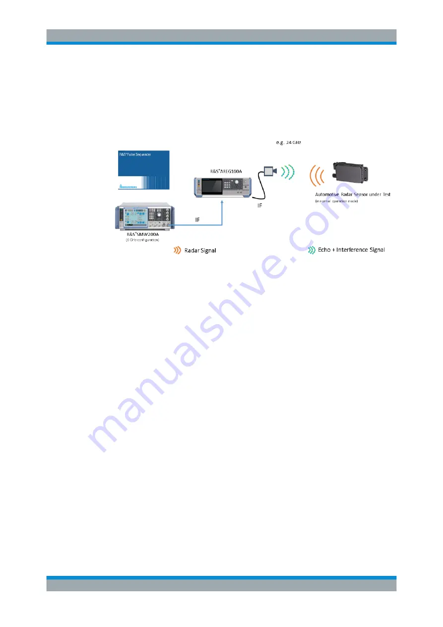
Testing Radar Sensors Against Interferers
The R&S
AREG100A provides an input interface in the IF domain (AUX IF In), which
allows in combination with any analog or vector signal generator the simulation of a
wide range of interferers together with the wanted echoes.
Figure 4-1: Testing Radar Sensors Against Interferers
1. Connect an R&S SMW200A to the TX IF IN connector of the R&S
AREG100A
base unit.
2. Set the frequency of the interfering signal to an IF frequency that will result at the
desired RF frequency. The resulting RF frequency can be calculated with the fol-
lowing equation:
f_RF = f_IF + f_LO
f_LO = 23.3 GHz for B124 options
f_LO = 75.3 GHz for B177 options
For B181 options, f_LO depends on the frequency setting.
● If the frequency setting for the R&S
AREG100A is below 78.5 GHz, f_LO =
75.3 GHz.
● If the frequency setting for the R&S
AREG100A is above 78.5 GHz, f_LO )
76.275 GHz.
3. The generated interfering signal is superimposed and upconverted into the E-band
together with the delayed echo signal from the simulated radar objects.
4. The influence of the interferer signals can now be observed and evaluated.
4.1.3
Measuring EIRP of Radar Sensor
The calibrated receive path from the Rx antenna port of the R&S
AREG100A to the
power measurement port at the front end allows to measure the sensor's EIRP (equiv-
alent isotropic radiated power) with a connected power sensor (e.g R&S NRP8SN
Power Sensor).
Use Cases