background image

Remote-Control Commands

IEEE 802.11 (a/b/g)

63

Operating Manual 1171.5283.12 ─ 18

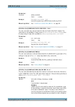
Parameters:

<RCosine>

float
Range: 

0  to  1.0

Increment:  0.01
*RST: 

0.22

Example: 

BB:WLAN:PAR:RCOS 0.22

sets the roll-off factor to 0. 22 for filter type Root Cosine.

Manual operation: 

See 

"Roll Off Factor / BxT"


on page 39

[:SOURce<hw>]:BB:WLAN:FILTer:PARameter:SPHase 

<SPhase>

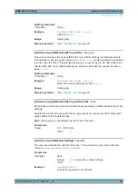
The command sets B x T for the Split Phase filter type.

Parameters:

<SPhase>

float
Range: 

0.15  to  2.5

Increment:  0.01
*RST: 

2

Example: 

BB:WLAN:PAR:SPH 0.5

sets B x T to 0.5 for the Split Phase filter type.

Manual operation: 

See 

"Roll Off Factor / BxT"


on page 39

[:SOURce<hw>]:BB:WLAN:CRATe:VARiation 

<Variation>

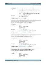
The command enters the output chip rate.

Parameters:

<Variation>

float
Range: 

1 kcps  to  40 Mcps

Increment:  1 Hz
*RST: 

11.0Mcps

Example: 

BB:WLAN:CRAT:VAR 4086001

'sets the output chip rate to 4.08 Mcps.

Manual operation: 

See 

" Chip Rate Variation "


on page 39

4.3


Trigger Settings

EXTernal<ch>

The numeric suffix to 

EXTernal<ch>

 distinguishes between the external trigger via

the [TRIGGER 1] (suffix 1) and [TRIGGER 2] (suffix 2) connector.

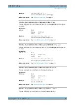
[:SOURce<hw>]:BB:WLAN:TRIGger:ARM:EXECute

............................................................64

[:SOURce<hw>]:BB:WLAN:TRIGger:EXECute

....................................................................64

[:SOURce<hw>]:BB:WLAN:TRIGger:EXTernal:SYNChronize:OUTPut

...................................64

Trigger Settings

Summary of Contents for AMU-K48

Page 1: ...IEEE 802 11 a b g Digital Standard for R S Signal Generators Operating Manual Operating Manual Version 18 1171528312 ÕÂá ...

Page 2: ...om Internet www rohde schwarz com Subject to change Data without tolerance limits is not binding R S is a registered trademark of Rohde Schwarz GmbH Co KG Trade names are trademarks of the owners 1171 5283 12 Version 18 IEEE 802 11 a b g The following abbreviations are used throughout this manual R S AMU200A is abbreviated as R S AMU R S SMATE200A is abbreviated as R S SMATE R S SMBV100A is abbrev...

Page 3: ... PLCP PPDU Format 14 2 3 Data Spreading and Modulation CCK PBCC 15 2 3 1 1 Mbps Data Rate with DBPSK Modulation 16 2 3 2 2 Mbps Data Rate with DQPSK Modulation 16 2 3 3 5 5 Mbps Data Rate with CCK Modulation 17 2 3 4 11 Mbps Data Rate with CCK Modulation 18 2 3 5 5 5 Mbps and 11 Mbps Data Rates with PBCC Modulation 19 2 3 6 22 Mbps and 33 Mbps Data Rates with PBCC Modulation 19 3 WLAN User Interfa...

Page 4: ... Clock Settings 40 3 6 1 Trigger In 41 3 6 2 Marker Mode 45 3 6 3 Marker Delay 46 3 6 4 Clock Settings 47 3 6 5 Global Settings 48 4 Remote Control Commands 49 4 1 General Commands 50 4 2 Filter Clipping Settings 59 4 3 Trigger Settings 63 4 4 Marker Settings 69 4 5 Clock Settings 74 4 6 PSDU Settings 76 List of Commands 85 Index 87 ...

Page 5: ...nit manual Contains the description of all instrument modes and functions It also provides an introduction to remote control a complete description of the remote control com mands with programming examples and information on maintenance instrument interfaces and error messages Includes the contents of the quick start guide man ual Software option manual Contains the description of the specific fun...

Page 6: ...describe the firmware installation The open source acknowledgment document provides verbatim license texts of the used open source software See the product page of the base unit e g at www rohde schwarz com firmware smbv100a Application Notes Application Cards White Papers etc These documents deal with special applications or background information on particu lar topics see www rohde schwarz com a...

Page 7: ...ully equipped product that is with all options instal led Thus some functions shown in the screenshots may not be available in your par ticular product configuration 1 2 3 Naming of Software Options In this operating manual we explicitly refer to options required for specific functions of the digital standard The names of software options for signal generators vary in the name of the instru ment b...

Page 8: ...Preface IEEE 802 11 a b g 8 Operating Manual 1171 5283 12 18 Conventions Used in the Documentation ...

Page 9: ...pansion to include the new data rates of 5 5 Mbps and 11 Mbps is defined in the 802 11b standard A new modulation mode complementary code keying CCK was introduced see following sections Standard 802 11g issued in 2003 extends standard 802 11b with higher transmission rates It includes the previous 802 11b standard and implements the OFDM transmis sion of standard 802 11a in the 2 4 GHz ISM band I...

Page 10: ...FDM orthogonal frequency division multiplex with 52 carriers as transmission method The symbol rate of the modulation on the individual carriers is 250 kHz A user data rate of up to 54 Mbps at a channel bandwidth of 20 MHz can be obtained by combining 48 useful carriers for data transmission 4 carriers are used for pilots and using 64QAM for subcarrier modulation With OFDM the individual carriers ...

Page 11: ...16QAM or 64QAM modulation can be used on the subcarriers Prior to the modulation the raw data are convolutionally coded with code rates of to being possible The frame structure can be seen in the figure below also indicated in the PPDU Con figuration dialog 2 1 1 PLCP Format The physical layer convergence protocol PLCP is a protocol layer between medium access control and the actual physical trans...

Page 12: ...has the best chance to obtain the information required for subsequent demodulation of the data sec tion 2 1 4 User Data The user data in the data section of the frame is finally taken to the receiver The data section may have a variable length of OFDM symbols and can be transmitted with one of the defined data rates between 6 and 54 Mbps The data section of the frame is sub divided into the fields...

Page 13: ...which significantly improves the faculties of the Viterbi decoder in the receiver for a correction The next stage performs the actual modulation of the individual OFDM carriers Depending on the set data rate the useful carriers are subjected to a uniform BPSK QPSK 16QAM or 64QAM modulation This is done by first calculating the I and Q coefficients of each carrier Gray coding is used to distribute ...

Page 14: ...s the data rate used in the PSDU field The rates 1 Mbps 2 Mbps 5 5 Mbps and 11 Mbps can be selected rates 22 MBps and 33 Mbps can be used in the optional PBCC modes The service field also helps to differentiate the modulation modes CCK or PBCC used for the higher data rates of 5 5 Mbps and 11 Mbps The length of the PSDU field is entered in µs in the Length field The CRC field contains a check sum ...

Page 15: ...on Depending on the PLCP PPDU format used the PLCP preamble and the PLCP header are combined in the packet builder The PSDU field of the packet is filled with the input data of the physical layer block In the next step all the packet data is scram bled The actual spreading and modulation of the data signal to the resulting chip rate of 11 Mcps comes next However the data rates and modulations of t...

Page 16: ...s CCK DQPSK PSDU 5 5 Mbps 11 Mcps PBCC BPSK PSDU 11 Mbps 11 Mcps PBCC QPSK PSDU 22 Mbps 11 Mcps PBCC 8PSK PSDU 33 Mbps 16 5 Mcps PBCC 8PSK The individual combinations of spreading coding and modulation are described below 2 3 1 1 Mbps Data Rate with DBPSK Modulation At a data rate of 1 Mbps the already scrambled data stream is DBPSK modulated according to the table below The resulting symbol seque...

Page 17: ...The phases φ1 φ2 φ3 φ4 are determined by these four bits φ1 is determined by the data bits d0 and d1 according to the following table which specifies different phases for even and odd modulation steps Dibit pattern d0 d1 d0 is first in time Even symbols phase change Odd symbols phase change 00 0 pi 01 pi 2 3pi 2 pi 2 11 pi 0 10 3pi 2 pi 2 pi 2 The phase φ1 must be interpreted relative to the phase...

Page 18: ... is basically the same as described for the 5 5 Mbps data rate In each modulation step eight successive bits d0 to d7 are taken from the data stream which is already scrambled The phases φ1 φ2 φ3 φ4 are determined by these eight bits φ1 is determined by the data bits d0 and d1 according to the following table which specifies different phases for even and odd modulation steps Dibit pattern d0 d1 d0...

Page 19: ...tic overview of this method For details refer to the standard Figure 2 2 Principle of PBCC modulation 2 3 6 22 Mbps and 33 Mbps Data Rates with PBCC Modulation 802 11g also defines the optional PBCC ER PBCC modes using the extended 22 Mbps and 33 Mbps rates In contrast to the 5 5 Mbps und 11 Mbps PBCC modes a rate 2 3 convolutional coder and 8PSK modulation are used With 33 Mbps also the clock rat...

Page 20: ...Introduction IEEE 802 11 a b g 20 Operating Manual 1171 5283 12 18 Data Spreading and Modulation CCK PBCC ...

Page 21: ...e made available in the lower section The upper section of the menu is where the IEEE 802 11a g WLAN digital standard is enabled The default settings are called and the physical layer mode the simulation mode and the frame type are selected Additional parameters for defining the signal length and a graph outlining the signal structure are indicated A button leads to the submenu for loading and sav...

Page 22: ...the default settings The values of the main parameters are listed in the following table Parameter Value State Not affected by Set to default Standard 802 11g Physical Layer Mode CCK Simulation Mode Framed Predefined Frames Data Sequence Length 1 frame Idle Time 0 1 ms Filter Gauss FSK 0 50 Chip Rate Variation 11 Mcps Clipping Off PPDU Configuration CCK PLCP P H Format Long PLPC PSDU Bit Rate CCK ...

Page 23: ... is specified in the File name entry field the directory selected in the save into field The file is saved by pressing the Save button File Manager Calls the File Manager The File Manager is used to copy delete and rename files and to create directories Remote command SOURce hw BB WLAN SETTing CATalog on page 55 SOURce hw BB WLAN SETTing LOAD on page 55 SOURce hw BB WLAN SETTing STORe on page 56 S...

Page 24: ...layer mode OFDM The OFDM orthogonal frequency division multiplexing physical layer supports a frame based transmission The OFDM signal is divided into 52 carriers The symbol rate of the modulation on the individual carriers is 250 kHz A user data rate of up to 54 Mbps at a channel bandwidth of 20 MHz can be obtained This is achieved by combining 48 useful carriers for data transmission 4 carriers ...

Page 25: ...ned by 802 11a g This mode can be used for simple tests for which only modulation and spectrum of the test signal are of interest No PLCP preamble and no signal field are generated in the unframed mode The idle time is also omitted The data field is identical to that of the framed mode and also contains the service and tail bits The length limitation stipulated by the standard to the maximum PSDU ...

Page 26: ...n page 51 PPDU Configuration This feature is available for Framed Mode only Calls the menu for configuration of the PPDU The menu differs for the physical layer modes The menu is described in Chapter 3 2 PPDU Sequence Configuration on page 27 Remote command n a Sequence Configuration This feature is available for Unframed Mode only Calls the menu for configuration of the signal in unframed modes T...

Page 27: ...ayers The PLCP preamble and header are used for synchronization and signaling purposes and are themselves divided into fields The details of the PPDU structure depend on the selected standard or more precisely on the physical layer mode see below In unframed mode the signal can be configured via the PSDU bit rate and PSDU modulation parameters as in the framed mode However a preamble or header is ...

Page 28: ...he menu the parameters of the data part PSDU are set In framed mode a distinction is made between the packet type or PPDU format with long or short PLCP physical layer convergence protocol A graph in the lower sec tions illustrates the structure of the PPDU framed mode or the unframed sequence unframed mode Framed Mode PPDU Sequence Configuration ...

Page 29: ...layer conver gence protocol Depending on the format selected the structure modulation and data rate of the PLCP preamble and header are modified The format currently set is shown in the graphic display in the lower part of the menu See Chapter 2 2 Physical Layer CCK PBCC on page 14 for description of the long and short format Remote command SOURce hw BB WLAN PLCP FORMat on page 52 PPDU Sequence Co...

Page 30: ...rrelation between data rate and modulation Data rate Possible modulation mode 1 Mbps Barker sequence DBPSK the information data sequence is spread with an 11 chip Barker sequence chip rate is 11 Mcps 2 Mbps Barker sequence DQPSK the information data sequence is spread with an 11 chip Barker sequence chip rate is 11 Mcps 5 5 Mbps CCK DQPSK or PBCC BPSK 11 Mbps CCK DQPSK or PBCC QPSK 22 Mbps PBCC 8P...

Page 31: ...s a function of the set PSDU bit rate and displays it at Data Length Remote command SOURce hw BB WLAN PSDU SCOunt on page 84 PSDU Data Sorce Selects the data source for the data field The following standard data sources are available All 0 All 1 An internally generated sequence containing 0 data or 1 data PNxx An internally generated pseudo random noise sequence Pattern An internally generated seq...

Page 32: ...bler and selects the mode of determining the initializa tion value OFF The scrambler is deactivated Random The scrambler is activated The initialization value of the scrambler is selected at random Each frame has a different random initialization value The value is also dif ferent if successive recalculations are applied The recalculations have the same setting parameters so that different signals...

Page 33: ...ame Remote command SOURce hw BB WLAN SCRambler PATTern on page 54 Interleaver Active OFDM Activates deactivates the interleaver Remote command SOURce hw BB WLAN ILEaver STATe on page 51 Service field hex Enters the value of the service field The standard specifies a default value of 0 Other values can be entered in hexadecimal form for test purposes or future extensions Remote command SOURce hw BB...

Page 34: ... a frame checksum These two functions can be controlled in the menu FCS checksum Activates deactivates the calculation of the FCS frame check sequence The stan dard defines a 32 bit 4 byte check sum to protect the MAC header and the user data frame body Remote command SOURce hw BB WLAN PSDU MAC FCSequence STATe on page 81 MAC Header Activates deactivates the generation of the MAC header for the PS...

Page 35: ...ONtrol MDATa on page 81 SOURce hw BB WLAN PSDU MAC FCONtrol WEP on page 81 SOURce hw BB WLAN PSDU MAC FCONtrol ORDer on page 81 Duration Id Enters the value of the duration ID field Depending on the frame type the 2 byte field Duration ID is used to transmit the asso ciation identity of the station The station transmits the frame or it indicates the duration assigned to the frame type Remote comma...

Page 36: ...start count for the transmission normally 0 and the number of packets required to increment the corre sponding counter can be defined for both numbers This is done with the parameters Start Number and Incremented every packet s see below Example An error free transmission of 50 packets no packet retransmission is to be simulated The sequence number should be incremented by 1 for each packet Since ...

Page 37: ...l Remote command SOURce hw BB WLAN PSDU MAC SCONtrol FRAGment INCRement on page 82 SOURce hw BB WLAN PSDU MAC SCONtrol SEQuence INCRement on page 82 Frame Body Indicates the length of the user data frame body Remote command n a FCS Indicates the length of the check sum Remote command n a 3 4 PPDU Graph The frame graph in the lower part of the menu indicates the configuration of the PPDU The frame ...

Page 38: ...this menu 3 5 1 Filter Settings Filter Sets the baseband filter This opens a selection window containing all the filters available to the instrument In 802 11a g OFDM mode a cosine filter with roll off factor 0 1 is used by default to achieve the spectrum masks requirement In 802 11b g CCK PBCC mode a gauss FSK filter with B T 0 5 is used by default to achieve the spectrum masks requirement Remote...

Page 39: ...M on page 62 Chip Rate Variation Enters the chip rate For each physical layer mode an own parameter is defined Which parameter is affected depends on the currently selected mode The chip rate entry changes the output clock and the modulation bandwidth and the synchronization signals that are output It does not affect the calculated chip sequence Remote command SOURce hw BB WLAN CRATe VARiation on ...

Page 40: ...pping does not take place Remote command SOURce hw BB WLAN CLIPping LEVel on page 59 Clipping Mode Selects the clipping method A graphic illustration of how the two methods work is given in the menu Vector i q The limit is related to the amplitude i q The I and Q components are mapped together the angle is retained Scalar i q The limit is related to the absolute maximum of all the I and Q values i...

Page 41: ...thout restarting signal and marker generation The Clock Settings section is where the clock source is selected and for an external source the clock type The buttons in the last section lead to submenu for general trigger clock and mapping settings 3 6 1 Trigger In The Trigger In section is where the trigger for the signal is set Various parameters are provided for the settings depending on which t...

Page 42: ... event occurs Then the signal is gener ated once to the length specified at Signal Duration Every subsequent trigger event internal or external causes a restart Remote command SOURce hw BB WLAN TRIGger SEQuence on page 69 Signal Duration Defines the length of the signal sequence to be output in the Single trigger mode The input is to be expressed in chips It is possible to output deliberately just...

Page 43: ...hreshold and the input impedance of the trigger signal Remote command SOURce hw BB WLAN TRIGger SOURce on page 67 Sync Output to External Trigger enabled for trigger source external Enables disables output of the signal synchronous to the external trigger event For R S SMBV instruments For or two or more R S SMBVs configured to work in a master slave mode for syn chronous signal generation configu...

Page 44: ...he processing time and starts with sample 0 i e the complete signal is outputted This mode is recommended for triggering of short signal sequences with signal duration comparable with the processing time of the instrument Remote command SOURce hw BB WLAN TRIGger EXTernal SYNChronize OUTPut on page 64 Trigger Delay Delays the trigger event of the signal from The external trigger source The other pa...

Page 45: ...ch signal sequence period selected number of frames Frame Start A marker signal is generated at the start of each frame period PPDU idle time Frame Active A marker signal is generated at the start of every active part of the frame The active data transfer part PPDU of a frame period is marked with high the inactive part idle time with low This marker can be used to decrease the carrier leakage dur...

Page 46: ... frame or slot The input is expressed in number of symbols samples If the setting Fix marker delay to dynamic range is enabled the setting range is restricted to the dynamic range In this range the delay of the marker signals can be set without restarting the marker and signal Remote command SOURce hw BB WLAN TRIGger OUTPut ch DELay on page 70 Current Range without Recalculation Displays the dynam...

Page 47: ...the synchronization and reference clock sig nal from another instrument working in a master mode Remote command SOURce hw BB WLAN CLOCk SYNChronization MODE on page 76 Set Synchronization Settings for R S SMBV only Performs automatically adjustment of the instrument s settings required for the syn chronization mode selected with the parameter Synchronization Mode Remote command SOURce hw BB WLAN C...

Page 48: ...d for permanent monitoring of the enabled and externally supplied clock signal Remote command CLOCk INPut FREQuency 3 6 5 Global Settings This section provides access general trigger clock and mapping settings Global Trigger Clock Settings Accesses the Global Trigger Clock Input Settings dialog This dialog is to set the trigger threshold the input impedance and the polarity of the clock and trigge...

Page 49: ... Signal Generator operating manual Common Suffixes The following common suffixes are used in remote commands Suffix Value range Description SOURce hw 1 2 available baseband signals OUTPut ch 1 4 available markers R S SMBV supports two markers EXTernal ch 1 2 external trigger connectors Placeholder root For commands that read out or save files in the default directory the default directory is set u...

Page 50: ... subsystem are described here General Commands 50 Filter Clipping Settings 59 Trigger Settings 63 Marker Settings 69 Clock Settings 74 PSDU Settings 76 4 1 General Commands SOURce hw BB WLAN FFORmat 51 SOURce hw BB WLAN ILEaver STATe 51 SOURce hw BB WLAN ITIMe 51 SOURce hw BB WLAN MODE 52 SOURce hw BB WLAN PLCP FORMat 52 SOURce hw BB WLAN PLCP LCBit STATe 53 SOURce hw BB WLAN PRESet 53 SOURce hw B...

Page 51: ...gs for Clear to Send ACK Predefined settings for Acknowledgement USER User defined settings response for query only RST USER Example BB WLAN SMODe FRAM selects framed mode BB WLAN FFOR RTS selects frame type RTS Manual operation See Predefined Frames on page 25 SOURce hw BB WLAN ILEaver STATe State The command activates deactivates the interleaver This command is only available in physical layer m...

Page 52: ...nd using 64QAM for subcarrier modulation With OFDM the individ ual carriers are superimposed mutually orthogonal which in the ideal case does not cause any intercarrier interference ICI CCK The CCK complementary code keying physical layer mode is used for the 5 5 Mbps and 11 Mbps data rates PBCC The PBCC packet binary convolutional coding physical layer can optionally be used instead of CCK modula...

Page 53: ... a standardized default for the IEEE 802 11a g standard The settings correspond to the RST values specified for the commands Example BB WLAN PRES resets all the IEEE 802 11a g settings to default values Usage Event Manual operation See Set to default on page 22 SOURce hw BB WLAN SCRambler MODE Mode The command activates deactivates the scrambler and selects the mode of determin ing the initializat...

Page 54: ... SCRambler PATTern Pattern BitCount The command enters the initialization value for scrambling mode User This value is then identical in each generated frame The command is only available for physical layer mode OFDM SOURce BB WLAN MODE OFDM Parameters Pattern numeric Range H0 0 to HFF 8 RST H0 0 BitCount integer Range 1 to 8 RST 1 Example BB WLAN SCR USER the scrambler is activated BB WLAN SCR PA...

Page 55: ...ilable Usage Query only Manual operation See Save Recall on page 23 SOURce hw BB WLAN SETTing DELete Filename This command deletes the selected file with IEEE 802 11a g WLAN settings The directory is set using command MMEM CDIRectory A path can also be specified in which case the files in the specified directory are read The file extension may be omit ted Only files with the file extension wlan wi...

Page 56: ...Setting parameters Filename string Example BB WLAN SETT STOR wlan_g stores the current settings into file wlan_g Usage Setting only Manual operation See Save Recall on page 23 SOURce hw BB WLAN SETTing STORe FAST Fast Determines whether the instrument performs an absolute or a differential storing of the settings Enable this function to accelerate the saving process by saving only the settings wit...

Page 57: ...ard The command selects the standard according to which the signal is simulated Parameters Standard STAN80211A STAN80211B STAN80211G STAN80211A The standard supports OFDM orthogonal frequency division multiplexing This modulation is defined by the IEEE 802 11a specification in the 5 GHz frequency band STAN80211B The standard includes the modulation mode CCK complemen tary code keying and the data ...

Page 58: ...quent sig nal filtering The command is only available for physical layer mode OFDM SOURce BB WLAN MODE OFDM Parameters State 0 1 OFF ON RST OFF Example BB WLAN TDW STAT OFF deactivates the time domain windowing Manual operation See Time Domain Windowing Active on page 33 SOURce hw BB WLAN TTIMe Ttime The command sets the transition time The transition time defines the overlap range of two OFDM sym...

Page 59: ...ng MODE 60 SOURce hw BB WLAN CLIPping STATe 60 SOURce hw BB WLAN FILTer TYPE 60 SOURce hw BB WLAN FILTer PARameter APCO25 61 SOURce hw BB WLAN FILTer PARameter COSine 61 SOURce hw BB WLAN FILTer PARameter GAUSs 61 SOURce hw BB WLAN FILTer PARameter LPASs 62 SOURce hw BB WLAN FILTer PARameter LPASSEVM 62 SOURce hw BB WLAN FILTer PARameter PGAuss 62 SOURce hw BB WLAN FILTer PARameter RCOSine 62 SOUR...

Page 60: ...B WLAN CLIP MODE SCAL selects the absolute maximum of all the I and Q values as the reference level BB WLAN CLIP LEV 80PCT sets the limit for level clipping to 80 of this maximum level BB WLAN CLIP STAT ON activates level clipping Manual operation See Clipping Mode on page 40 SOURce hw BB WLAN CLIPping STATe State Activates level clipping Clipping The value is defined with the command SOURce BB WL...

Page 61: ...ters Apco25 float Range 0 05 to 0 99 Increment 0 01 RST 0 2 Example BB WLAN PAR APCO25 0 2 sets the roll off factor to 0 2 for filter type APCO25 Manual operation See Roll Off Factor BxT on page 39 SOURce hw BB WLAN FILTer PARameter COSine Cosine The command sets the roll off factor for the Cosine filter type Parameters Cosine float Range 0 05 to 1 0 Increment 0 01 RST 0 1 Example BB WLAN PAR COS ...

Page 62: ...B WLAN FILTer PARameter LPASSEVM LPassevm The command sets the cut off frequency factor for the Lowpass filter EVM optimiza tion type Parameters LPassevm float Range 0 05 to 2 0 RST 0 5 Example BB WLAN FILT PAR LPASSEVM 0 5 the cut of frequency factor is set to 0 5 Manual operation See Cut Off Frequency Factor on page 39 SOURce hw BB WLAN FILTer PARameter PGAuss PGauss The command sets the roll of...

Page 63: ...0 5 for the Split Phase filter type Manual operation See Roll Off Factor BxT on page 39 SOURce hw BB WLAN CRATe VARiation Variation The command enters the output chip rate Parameters Variation float Range 1 kcps to 40 Mcps Increment 1 Hz RST 11 0Mcps Example BB WLAN CRAT VAR 4086001 sets the output chip rate to 4 08 Mcps Manual operation See Chip Rate Variation on page 39 4 3 Trigger Settings EXTe...

Page 64: ...ts Armed_Retrigger mode i e every trigger event causes sig nal generation to restart BB WLAN TRIG EXEC executes a trigger signal generation is started BB WLAN TRIG ARM EXEC signal generation is stopped BB WLAN TRIG EXEC executes a trigger signal generation is started again Usage Event Manual operation See Arm on page 42 SOURce hw BB WLAN TRIGger EXECute The command executes a trigger The internal ...

Page 65: ...ggering of short signal sequen ces with signal duration comparable with the processing time of the instrument RST ON Example BB WLAN TRIG SOUR EXT sets external triggering BB WLAN TRIG EXT SYNC OUTP ON enables synchrounous output to external trigger Manual operation See Sync Output to External Trigger on page 43 SOURce hw BB WLAN TRIGger OBASeband DELay Delay The command specifies the trigger dela...

Page 66: ...gnal is not generated A trigger event did not occur in the triggered modes or signal generation was stopped by the com mand BB WLAN TRIG ARM EXECute armed trigger modes only Example BB WLAN TRIG SOUR EXT sets external triggering via the TRIGGER 1 connector BB WLAN TRIG MODE ARET selects the Armed_Retrigger mode BB WLAN TRIG RMOD queries the current status of signal generation Response RUN the sign...

Page 67: ...le trigger mode SOUR BB WLAN SEQ SING Parameters Slunit FRAMe CHIP SEQuence FRAMe Unit Frame A single frame is generated after a trigger event CHIP Unit Chip A single chip is generated after a trigger event SEQuence Unit Sequence Length A single sequence is generated after a trigger event RST SEQuence Example BB WLAN SEQ SING sets trigger mode Single BB WLAN TRIG SLUN FRAM sets unit Frame for the ...

Page 68: ...1 chip RST 0 0 Example BB WLAN TRIG SOUR EXT sets an external trigger via the TRIGGER 1 connector BB WLAN TRIG DEL 50 sets a delay of 50 chips for the trigger Manual operation See Trigger Delay on page 44 SOURce hw BB WLAN TRIGger EXTernal ch INHibit Inhibit The command specifies the number of chips by which a restart is to be inhibited follow ing a trigger event This command applies only in the c...

Page 69: ...e automatically toggles to RETRIG mode Every subsequent trigger event causes a restart Signal generation is stopped with command SOUR BB WLAN TRIG ARM EXEC and started again when a trigger event occurs SINGle The modulation signal is generated only when a trigger event occurs Then the signal is generated once to the length specified with command SOUR BB WLAN TRIG SLEN Every subsequent trigger even...

Page 70: ...gnal If a delay is entered in setting ON but is outside this range the maximum possible delay is set and an error message is generated Parameters Fixed 0 1 OFF ON RST OFF Example BB WLAN TRIG OUTP DEL FIX ON restricts the marker signal delay setting range to the dynamic range Manual operation See Fix marker delay to current range on page 46 SOURce hw BB WLAN TRIGger OUTPut ch DELay Delay for R S S...

Page 71: ...ee Current Range without Recalculation on page 46 SOURce hw BB WLAN TRIGger OUTPut ch DELay MINimum for R S SMx AMU instrumenets only The command queries the minimum marker delay for set ting BB WLAN TRIGger OUTPut DELay FIXed ON Return values Minimum float Range 0 to max Example BB WLAN TRIG OUTP DEL FIX ON restricts the marker signal delay setting range to the dynamic range BB WLAN TRIG OUTP DEL...

Page 72: ... RESTart Example BB WLAN TRIG OUTP2 MODE FRAM selects the frame marker signal on output MARKER 2 Manual operation See Marker Mode on page 45 SOURce hw BB WLAN TRIGger OUTPut ch ONTime OnTime SOURce hw BB WLAN TRIGger OUTPut ch OFFTime OffTime The command sets the number of chips in a period ON time OFF time during which the marker signal in setting SOURce BB WLAN TRIGger OUTPut MODE RATio on the m...

Page 73: ...Se The resulting pulse frequency is derived by dividing the symbol rate by the divider Parameters Divider float Range 2 to 1024 Increment 1 RST 2 Example BB WLAN TRIG OUTP2 PULS DIV 2 sets the divider to 2 for the marker signal on output MARKER 2 BB WLAN TRIG OUTP2 FREQ queries the resulting pulse frequency of the marker signal Response 66 000 the resulting pulse frequency is 66 kHz Manual operati...

Page 74: ...LOCk MODE Mode The command enters the type of externally supplied clock BB WLAN CLOCk SOURce EXTernal When MCHip is used a multiple of the chip clock is supplied via the CLOCK connector and the chip clock is derived internally from this The multiplier is entered with the com mand SOURce hw BB WLAN CLOCk MULTiplier For two path instruments the only numerical suffix allowed for SOURce is 1 since the...

Page 75: ... is only possible for path A since the external clock source is permanently allocated to path A selecting AINTernal is only possible for path B Parameters Source INTernal EXTernal AINTernal INTernal The internal clock reference is used EXTernal The external clock reference is supplied to the CLOCK connec tor RST INTernal Example BB WLAN CLOC SOUR EXT selects an external clock reference The clock i...

Page 76: ...ments must have the same length and type Avoid unnecessary cable length and branching points Parameters Mode NONE MASTer SLAVe NONE The instrument is working in stand alone mode MASTer The instrument provides all connected instrument with its syn chronization including the trigger signal and reference clock signal SLAVe The instrument receives the synchronization and reference clock signal from an...

Page 77: ... PSDU MAC SCONtrol FRAGment INCRement 82 SOURce hw BB WLAN PSDU MAC SCONtrol FRAGment STARt 82 SOURce hw BB WLAN PSDU MAC SCONtrol SEQuence INCRement 82 SOURce hw BB WLAN PSDU MAC SCONtrol SEQuence STARt 83 SOURce hw BB WLAN PSDU MAC SCONtrol STATe 83 SOURce hw BB WLAN PSDU MAC STATe 83 SOURce hw BB WLAN PSDU MODulation 84 SOURce hw BB WLAN PSDU SCOunt 84 SOURce hw BB WLAN PSDU BRATe Brate The com...

Page 78: ...e hw BB WLAN PSDU DATA DSELect ZERO ONE Internal 0 and 1 data is used PATTern Internal data is used The bit pattern for the data is defined by the command SOURce hw BB WLAN PSDU DATA PATTern RST PN9 Example BB WLAN PSDU DATA PATT selects as the data source for the data fields of burst 0 the bit pattern defined with the following command BB WLAN PSDU DATA PATT H3F 8 defines the bit pattern Manual o...

Page 79: ... 1 to 64 RST 1 Example BB WLAN PSDU MAC DATA PATT H3F 8 defines the bit pattern Manual operation See PSDU Data Sorce on page 31 SOURce hw BB WLAN PSDU DLENgth Dlength The command sets the data length in bytes In the framed mode data field lengths of up to 4095 bytes are possible This corresponds to the maximum data length The unframed mode offers a data length of up to 100000 bytes If the data fie...

Page 80: ...hw BB WLAN PSDU MAC ADDRess ch STATe State The command activates deactivates the selected address field The MAC header can only be configured in framed mode SOURce BB WLAN SMODe FRAMed Parameters State 0 1 OFF ON RST OFF Example BB WLAN PSDU MAC ADDR2 STAT ON activates generation of address field 2 SOURce hw BB WLAN PSDU MAC DID Did The command enters the value of the duration Id field Depending o...

Page 81: ...e hw BB WLAN PSDU MAC FCONtrol ORDer Order SOURce hw BB WLAN PSDU MAC FCONtrol PMANagement Pmanagement SOURce hw BB WLAN PSDU MAC FCONtrol PVERsion PVersion SOURce hw BB WLAN PSDU MAC FCONtrol RETRy Retry SOURce hw BB WLAN PSDU MAC FCONtrol SUBType Subtype SOURce hw BB WLAN PSDU MAC FCONtrol TDS Tds SOURce hw BB WLAN PSDU MAC FCONtrol TYPE Type SOURce hw BB WLAN PSDU MAC FCONtrol WEP Wep The comma...

Page 82: ...B WLAN PSDU MAC SCON FRAG INCR 2 two packets are required to increment the counter of the frag ment bits Manual operation See Sequence Control on page 35 SOURce hw BB WLAN PSDU MAC SCONtrol FRAGment STARt Start The command enters the start number of the fragment bits of the sequence control The MAC header can only be configured in framed mode SOURce BB WLAN SMODe FRAMed Parameters Start integer Ra...

Page 83: ... SMODe FRAMed Parameters Start integer Range H0 12 to HFFF 12 RST H0 12 Example BB WLAN PSDU MAC SCON SEQ STAR H4 4 sets the start value of the sequence bits of the sequence control Manual operation See Sequence Control on page 35 SOURce hw BB WLAN PSDU MAC SCONtrol STATe State The command activates deactivates the sequence control The MAC header can only be configured in framed mode SOURce BB WLA...

Page 84: ...s the modulation mode Response DQPSK Usage Query only Manual operation See PSDU Modulation on page 30 SOURce hw BB WLAN PSDU SCOunt Scount The command sets the number of data symbols If the number of OFDM data symbols is changed the generator calculates the data field length as a function of the set PSDU bit rate The command is only available in physical layer mode OFDM SOURce BB WLAN MODE OFDM If...

Page 85: ...ATe 51 SOURce hw BB WLAN ITIMe 51 SOURce hw BB WLAN MODE 52 SOURce hw BB WLAN PLCP FORMat 52 SOURce hw BB WLAN PLCP LCBit STATe 53 SOURce hw BB WLAN PRESet 53 SOURce hw BB WLAN PSDU BRATe 77 SOURce hw BB WLAN PSDU BSPReading STATe 77 SOURce hw BB WLAN PSDU DATA 78 SOURce hw BB WLAN PSDU DATA DSELect 78 SOURce hw BB WLAN PSDU DATA PATTern 79 SOURce hw BB WLAN PSDU DLENgth 79 SOURce hw BB WLAN PSDU ...

Page 86: ...ndowing STATe 58 SOURce hw BB WLAN TRIGger ARM EXECute 64 SOURce hw BB WLAN TRIGger EXECute 64 SOURce hw BB WLAN TRIGger EXTernal SYNChronize OUTPut 64 SOURce hw BB WLAN TRIGger OBASeband DELay 65 SOURce hw BB WLAN TRIGger OBASeband INHibit 65 SOURce hw BB WLAN TRIGger OUTPut DELay FIXed 70 SOURce hw BB WLAN TRIGger OUTPut ch DELay 70 SOURce hw BB WLAN TRIGger OUTPut ch DELay MAXimum 71 SOURce hw ...

Page 87: ...lipping 26 Fix marker delay to current range 46 Frame body 37 Frame control 35 G Generate waveform file 23 Global trigger clock settings 48 I Idle time 26 Increment every 37 Interleaver active OFDM 33 L Load IEEE 802 11a g WLAN settings 23 M Marker delay 46 Marker mode 45 Measured external clock 48 Multiplier 48 N Number of data symbols 31 O OFDM mode 24 ON OFF ratio marker 45 Online help 5 Online...

Page 88: ...lt 22 Signal duration 42 Simulation mode 24 Standard 23 Standard settings 22 Start number 36 State 22 State clipping 39 Stopped 42 Sync Output to external trigger 43 Synchronization mode 47 Synchronization Mode 76 T Time domain windowing active OFDM 33 Transition time 33 Trigger delay 44 Trigger inhibit 45 Trigger mode Armed 42 Auto 42 Retrigger 42 Single 42 Trigger parameters 26 Trigger source 43...

Reviews: