


Connecting External Accessories
R&S
®
ZVA
1145.1090.62 1.18
E-1
Attention!
The monitor must be connected while the instrument is switched off (in standby
mode). Otherwise correct operation can not be guaranteed.
The monitor displays the magnified analyzer screen with all diagram areas, measurement results and
control elements.
With an additional mouse or keyboard connected to the analyzer, you can control the
measurement from the monitor. If desired, click
Display – Config/View – Hardkey Bar
to add the Font
Panel Keys to the analyzer screen.
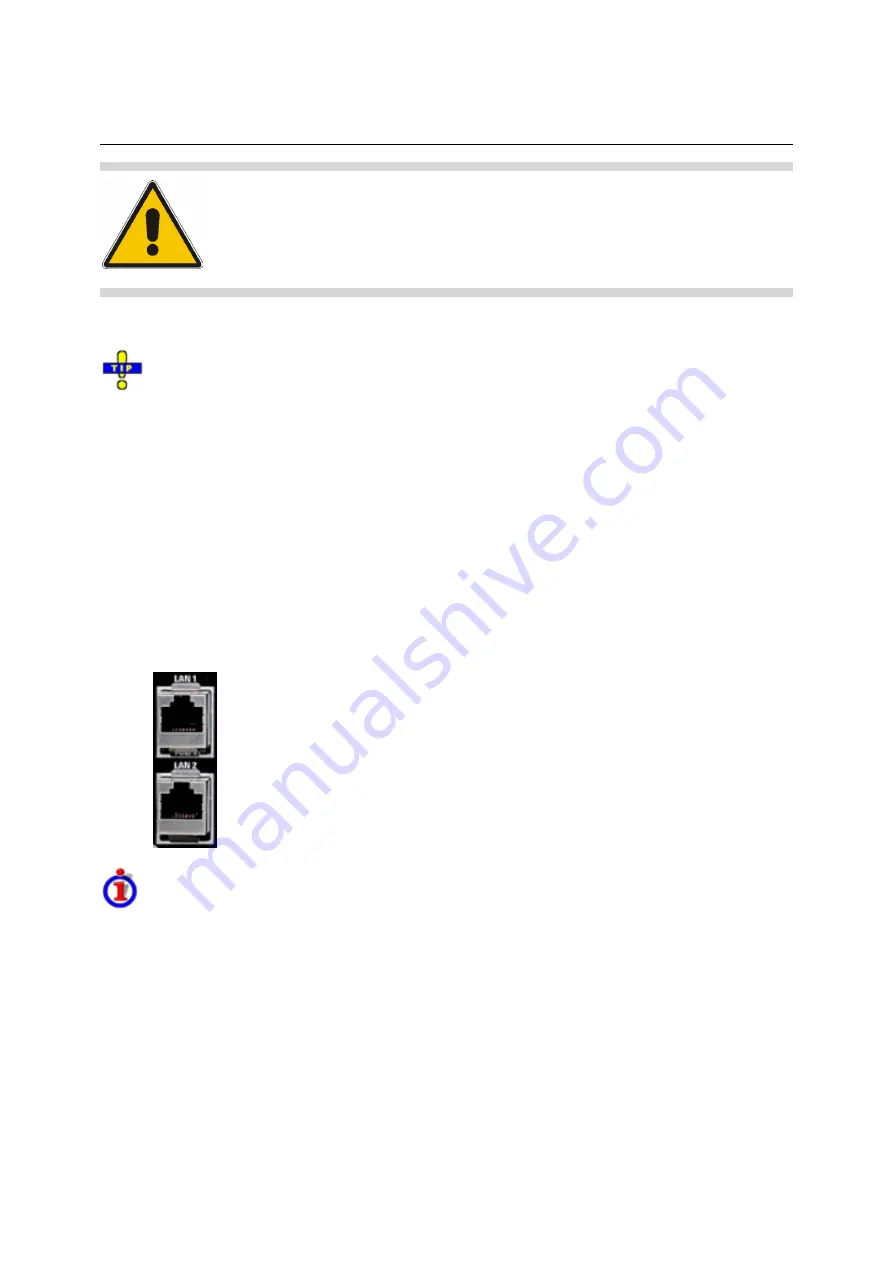
Connecting a LAN Cable
A LAN cable can be connected to one of the LAN connectors on the rear panel of the analyzer. To
establish a LAN connection proceed as follows:
1. Refer to section
Assigning an IP Address
and learn how to avoid connection errors.
2. Connect an appropriate LAN cable to one of the LAN ports. Use a commercial RJ-45 cable to
establish a non-dedicated network connection, or a cross-over RJ-45 cable to establish a
dedicated connection between the analyzer and a single PC.
Dedicated vs. non-dedicated network connections
There are two methods to establish a LAN connection of the analyzer:
•
A non-dedicated network (Ethernet) connection from the analyzer to an existing network made with
an ordinary RJ-45 network cable. The analyzer is assigned an IP address and can coexist with a
computer and with other hosts on the same network.
•
A dedicated network connection between the analyzer and a single computer made with a cross-
over RJ-45 network cable. The computer must be equipped with a network adapter and is directly
connected to the analyzer. The use of hubs, switches, or gateways is not needed, however, data
transfer is still made using the TCP/IP protocol.
The IP address information is displayed in the Info – Setup Info dialog.
Summary of Contents for 1145.1010.04/05/06
Page 10: ......
Page 20: ......
Page 22: ......
Page 48: ......
Page 70: ......
Page 72: ......
Page 90: ......
Page 92: ......
Page 108: ......
Page 156: ......
Page 162: ......
Page 406: ...Display Menu R S ZVA ZVB ZVT 1145 1084 12 4 244 E 6 Stack Tile Horizontally Tile Vertically...
Page 450: ...Status Reporting System R S ZVA ZVB ZVT 1145 1084 12 5 18 E 1...
Page 462: ......
Page 766: ......
Page 772: ......
Page 792: ......
Page 794: ......
Page 808: ......


