Quick Start
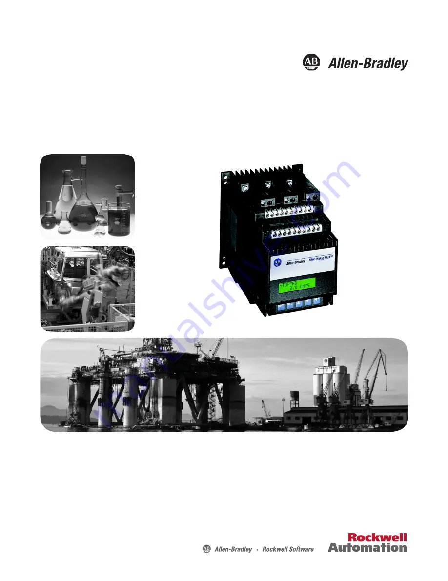
SMC Dialog Plus™ Controller
Bulletin 150
Page 1: ...Quick Start SMC Dialog Plus Controller Bulletin 150 ...
Page 2: ...s assumed by Rockwell Automation Inc with respect to use of information circuits equipment or software described in this manual Reproduction of the contents of this manual in whole or in part without written permission of Rockwell Automation Inc is prohibited Throughout this manual when necessary we use notes to make you aware of safety considerations SMC Dialog Plus Allen Bradley Rockwell Softwar...
Page 3: ...fety precautions For safety of maintenance personnel as well as others who might be exposed to electrical hazards associated with maintenance activities follow all local safety related work practices e g the NFPA 70E Part II in the United States Maintenance personnel must be trained in the safety practices procedures and requirements that pertain to their respective job assignments For detailed SM...
Page 4: ...ntrol precautions are required when installing testing servicing or repairing the assembly Component damage may result if ESD control procedures are not followed If you are not familiar with static control procedures refer to applicable ESD protection handbooks ATTENTION An incorrectly applied or installed controller can damage components or reduce product life Wiring or application errors such as...
Page 5: ...ics inhibit the controller s current measurement capability To compensate for additional motor heating that may result the controller uses motor thermal modeling which increments motor thermal usage This compensation takes place when these options are in use Preset Slow Speed Smart Motor Braking Accu Stop and Slow Speed with Braking ATTENTION Only one peripheral device can be connected to the SCAN...
Page 6: ...to be used as an emergency stop Refer to applicable standards for emergency stop requirements ATTENTION Accu Stop and Slow Speed with Braking are not intended to be used as an emergency stop Refer to applicable standards for emergency stop requirements ATTENTION The fast acting current limiting fuses specified in Table 2 C of the user manual may not provide branch circuit protection Branch circuit...
Page 7: ...ules may be placed on the line load or both sides of the SMC Do not place protective modules on the load side of the SMC when when using pump or braking control ATTENTION When installing or inspecting the protective module make sure that the controller has been disconnected from the power source The protective module should be inspected periodically for damage or discoloration Replace if necessary...
Page 8: ...DC Refer to the product nameplate prior to applying control power Connect control power to the controller at terminals 11 and 12 The control power requirement for the control module is 40 VA For controllers rated 97 1000 A control power is also required for the heatsink fans as defined in Table A Depending on the specific application additional control circuit transformer VA capacity may be requir...
Page 9: ...t 14 Logic Ground 15 Dual Ramp Option Input 16 Start Input 17 Stop Input 18 Auxiliary Relay Common 19 N O Auxiliary Contact 1 20 N C Auxiliary Contact 2 21 Not Used 22 Not Used 23 Not Used 24 Not Used 25 Converter Module Fanning Strip Connection 26 Converter Module Fanning Strip Connection 27 Converter Module Fanning Strip Connection 28 Converter Module Fanning Strip Connection 29 Auxiliary Contac...
Page 10: ...rovides typical wiring diagrams for the control options for example Pump Control Stop 11 12 13 14 15 16 17 18 19 20 Start 3 Phase Input Power Branch Protection Fast acting SCR Fuses optional SMC Dialog Plus Controller M Customer supplied L1 1 L2 3 L3 5 T1 2 T2 4 T3 6 Fan Power Terminals 97 1000 A SMC Dialog Plus Control Terminals Internal Auxiliary Contacts Factory Set 110 120V AC To Supply 1 2 3 ...
Page 11: ...t key alternately causes the top or bottom line of the display to become active indicated by flashing first character In parameter modification with series A FRN 3 00 or greater and series B human interface modules Select moves the cursor from the least significant digit to the most significant Up Down Arrows These keys are used to increment and decrement a parameter value or to scroll through the...
Page 12: ...rch are only available when using a Series B Bulletin 1201 human interface module Password protected English is currently the only available language Power Up and Status Display Choose Mode Program read write Control Status Display read only Password Search read only Control Logic Fault Queue Linear List Metering Basic Setup Advanced Setup Faults Calibrate Language OPERATION LEVEL MODE LEVEL GROUP...
Page 13: ... LEVEL PARAMETER LEVEL ESC or Clear Fault Fault Buffer 1 Fault Buffer 2 Fault Buffer 3 Fault Buffer 4 Fault Buffer 5 SMC Option Starting Mode Ramp Time 1 Initial Torque 1 Curr Limit Level Kickstart Time Stall Delay Energy Saver Aux Contacts 1 2 Aux Contact 3 Contact 3 Config Option Settings Parameter Mgmt SMC Option Starting Mode Dual Ramp Ramp Time 1 Initial Torque 1 Ramp Time 2 Initial Torque 2 ...
Page 14: ...e connected motor A clamp on ammeter which provides a true rms measurement and has a published accuracy of 1 Fluke model 33 or equal is required to perform this procedure Parameter Setting Starting Mode Soft Start Ramp Time 10 seconds Initial Torque 70 of locked rotor torque Kickstart Off Energy Saver Off Stall Off Phase Rebalance Off Auxiliary Contacts Normal Service Factor 1 15 Overload Class Of...
Page 15: ...accuracy Description Action Display 1 Check all power and control wiring connections to the controller and motor Apply a start command to the controller and check for motor rotation to full speed _ 2 Using the clamp on ammeter measure the three phase motor currents Place the ammeter around the phase with the largest current draw _ 3 In the Calibrate group scroll to the Calibration parameter 4 Moni...
Page 16: ... the Select key Scroll with the Up Down keys to Store In EE selection Press the Enter key to save the settings to EEPROM ATTENTION After calibration is completed program the desired overload class and save the setting to the controller s EEPROM ATTENTION The method of current measurement is not applicable to the multi motor installations or resistive heating loads Utilization of the Bulletin 825 c...
Page 17: ...or control from a connected human interface module you must take the following programming steps Series A 1 Enter into the Program mode 2 Select the Linear List programming group 3 Scroll to the Logic Mask parameter number 85 4 Program the Logic Mask parameter for a value of 4 5 Press Enter Series B 1 Enter the Control Status mode 2 Select the Enable option of Control Logic 3 Press Enter IMPORTANT...
Page 18: ...18 Rockwell Automation Publication 150 QS002B EN P October 2011 Quick Start Notes ...
Page 19: ......
Page 20: ...u experience a problem within the first 24 hours of installation review the information that is contained in this manual You can contact Customer Support for initial help in getting your product up and running New Product Satisfaction Return Rockwell Automation tests all of its products to ensure that they are fully operational when shipped from the manufacturing facility However if your product i...