


224
Rockwell Automation Publication 520-UM001K-EN-E - August 2021
Appendix E Encoder/Pulse Train Usage and Position StepLogic Application
Note: Incremental move commands will cause the drive to move the amount
specified based on the current position. Absolute commands are always with
reference to “Home”.
[Pos Reg Filter] provides a low pass filter at the input of the position
regulator.
[Pos Reg Gain] is a single adjustment for increasing or decreasing the
responsiveness of the position regulator. For faster response, the filter should
be reduced and/or the gain should be increased. For smoother response with
less overshoot, the filter should be increased and/or the gain should be
reduced. In general, the gain will have a larger effect on most systems than the
filter.
Homing Routine
This drive supports incremental encoders only. Therefore, when the drive
powers up it will reset the current position to zero. If this is known to be
correct the position routine can be started without further adjustment.
However, in most applications the drive will need to be “homed” after each
power-up and prior to starting the position routine.
This can be accomplished in one of the following two ways:
1. Manual Homing–Program the following drive parameters:
,
...
[DigIn TermBlk xx] = 37 “Pos Redefine”
Program one of the digital inputs to 37 “Pos Redefine”. Then, move the
system into the home position with a run command, a jog command,
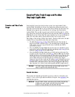
Positioning Settings (Digit 4)
Required
Setting
Accel/Decel
Param. Used
StepLogic
Output State
Direction
From Home
Type of
Command
0
Accel/Decel 1
Off
FWD
Absolute
1
Accel/Decel 1
Off
FWD
Incremental
2
Accel/Decel 1
Off
REV
Absolute
3
Accel/Decel 1
Off
REV
Incremental
4
Accel/Decel 1
On
FWD
Absolute
5
Accel/Decel 1
On
FWD
Incremental
6
Accel/Decel 1
On
REV
Absolute
7
Accel/Decel 1
On
REV
Incremental
8
Accel/Decel 2
Off
FWD
Absolute
9
Accel/Decel 2
Off
FWD
Incremental
A
Accel/Decel 2
Off
REV
Absolute
b
Accel/Decel 2
Off
REV
Incremental
C
Accel/Decel 2
On
FWD
Absolute
d
Accel/Decel 2
On
FWD
Incremental
E
Accel/Decel 2
On
REV
Absolute
F
Accel/Decel 2
On
REV
Incremental
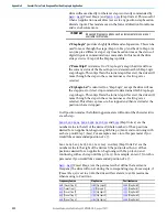
Settings (Digit 2 and 1)
Setting Description
0
Skip Step (Jump Immediately)
1
Step Based on [Stp Logic Time x]
2
Step if “Logic In 1” is Active
3
Step if “Logic In 2” is Active
4
Step if “Logic In 1” is Not Active
5
Step if “Logic In 2” is Not Active
6
Step if either “Logic In 1” or “Logic In 2” is Active
7
Step if both “Logic In 1” and “Logic In 2” are Active
8
Step if neither “Logic In 1” nor “Logic In 2” is Active
9
Step if “Logic In 1” is Active and “Logic In 2” is Not
Active
A
Step if “Logic In 2” is Active and “Logic In 1” is Not
Active
b
Step after [Stp Logic Time x] and “Logic In 1” is
Active
C
Step after [Stp Logic Time x] and “Logic In 2” is
Active
d
Step after [Stp Logic Time x] and “Logic In 1” is Not
Active
E
Step after [Stp Logic Time x] and “Logic In 2” is
Not Active
F
Do Not Step/Ignore Digit 2 Settings
Use the Wizard in Connected Components Workbench software to
simplify setup instead of manually configuring the parameters.
Summary of Contents for Allen-Bradley PowerFlex 520 Series
Page 8: ...8 Rockwell Automation Publication 520 UM001K EN E August 2021 Table of Contents Notes ...
Page 68: ...68 Rockwell Automation Publication 520 UM001K EN E August 2021 Chapter 2 Start Up Notes ...
Page 236: ...236 Rockwell Automation Publication 520 UM001K EN E August 2021 Appendix F PID Set Up Notes ...
Page 270: ...270 Rockwell Automation Publication 520 UM001K EN E August 2021 Index Notes ...