34
Rockwell Automation Publication 440G-UM001B-EN-P - May 2016
Chapter 4
Description of Operation
With Inactive Guard Lock Monitoring
1. Switch on operating voltage.
The State status indicator flashes (5 Hz) as the device performs a self-test
(up to 8 seconds). When the self-test is complete, the State status indicator
flashes at regular intervals.
2. Close all safety guards and insert the bolt tongue into the locking module.
As soon as the bolt tongue is inserted in the locking module, the safety
outputs FO1A/FO1B are ON (independent of whether the guard door is
locked or unlocked).
• The machine must not start automatically.
• The State status indicator is ON. The lock status indicator is ON for a
long time with a short interruption (guard door unlocked) or is ON
continuously (guard door locked).
3. To start the machine, use the control system.
4. Open the guard door (for Power to Release versions, use the control system
to unlock the guard door).
• The machine must switch off and it must not be possible to start it as
long as the safety guard is open.
Repeat steps two through four for each safety guard.
Change Device Configuration
(using DIP switches)
The Access Box can be configured using DIP switches. The following settings
are possible:
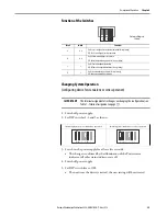
• Changing system operation (standalone or series operation)
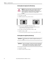
• Deactivating guard lock monitoring
• Deactivating release monitoring
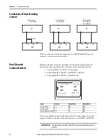
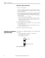
Figure 1 - Location of the Switches
Sticker with factory settings
Dip switches

