


Publication 1747-UM013B-EN-P - January 2005
4-34
Scanner Configuration and Programming
2.
Assign the scanner to a physical slot in the SLC processor’s
chassis by selecting
Scanner
from the list. If the scanner
selection is not available, select
OTHER
from the I/O
Configuration Screen and enter the Code ID number:
13608.
3.
Enter the number of
Scanned Input
and
Output Words
using the
Specialty I/O and Advanced Setup menus
.
The default value is 32 I/O words. You can specify less than 32
and reduce the processor scan time by transferring only the part
of the input and output image that your application requires.
4.
Using the
Specialty I/O Configuration
menu, set the M1 and M0
file sizes to 32 words (48 words if using complementary I/O). 32
words is the minimum required for operation. If you do not set
the M1 and M0 file sizes to at least 32 words the programming
device will not allow you to access the M files in the SLC control
program.
If you are using the block transfer (BT) function, you should set
the M1 and M0 file sizes to 3,300. Refer to Chapter 5 before
completing this selection.
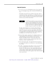
5.
Set the G file size to 3 (5 if using complementary I/O) using the
Specialty I/O Configuration
menu.
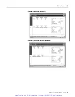
6.
Enter your setup information using the
Modify G File
menu.
IMPORTANT
Do not set either of these values to 0. If you
do, the scanner will not work correctly.
IMPORTANT
SLC 5/02 processors scan chassis I/O slots left
to right starting at slot 1, regardless of the
module type. SLC 5/03 and later processors
scan slots with discrete I/O modules first, left
to right starting at slot 1, and then slots with
specialty modules, left to right starting at slot 1.
Artisan Technology Group - Quality Instrumentation ... Guaranteed | (888) 88-SOURCE | www.artisantg.com