background image

Publication 1747-UM013B-EN-P - January 2005

4-10

        Scanner Configuration and Programming

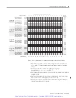
Illegal Configuration Examples

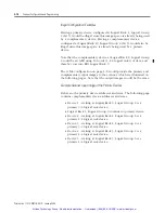
Having a primary device configured at Logical Rack 1, Logical Group 
2 (bit 5) would be illegal since this image space is already being used 
by a complementary device. Having a complementary device 
configured at Logical Rack 10, Logical Group 2 (bit 9) would also be 
illegal since this image space is already being used by a primary 
device.

Note that the complementary device at Logical Rack 8, Logical Group 
2 could be an ASB using 10 words (1-1/4 logical racks) of data, and 
thereby cross into RIO Logical Rack 9.

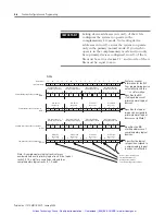
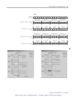
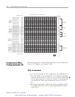
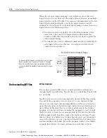
The G file configuration on page 2-6 would provide the primary and 
complementary input images to the scanner, which are illustrated on 
the following pages. Note that the output images would be the same.

Example Scanner Input Image of the Primary Devices

Below are the primary device addresses and sizes. The following page 
contains complementary device addresses and sizes.

Device 1 - starting at Logical Rack 0, Logical Group 2 is a 
primary 3/4 logical rack device. 

Logical Rack 1, Logical Group 0 contains no primary device.

Device 2 - starting at Logical Rack 1, Logical Group 6 is a 
primary 1/4 logical rack device.

Device 3 - starting at Logical Rack 2, Logical Group 0 is a 
primary 3/4 logical rack device.

Device 4 - starting at Logical Rack 3, Logical Group 2 is a 
primary 1/4 logical rack device.

Device 5 - starting at Logical Rack 3, Logical Group 6 is a 
primary 1/4 logical rack device.

Artisan Technology Group - Quality Instrumentation ... Guaranteed | (888) 88-SOURCE | www.artisantg.com

Summary of Contents for Allen-Bradley 1747-SN

Page 1: ...service in house repair center WE BUY USED EQUIPMENT Sell your excess underutilized and idle used equipment We also offer credit for buy backs and trade ins www artisantg com WeBuyEquipment REMOTE IN...

Page 2: ...RemoteI OScanner 1747 SN User Manual Artisan Technology Group Quality Instrumentation Guaranteed 888 88 SOURCE www artisantg com...

Page 3: ...se based on the examples and diagrams No patent liability is assumed by Rockwell Automation Inc with respect to use of information circuits equipment or software described in this manual Reproduction...

Page 4: ...right of this paragraph The table below lists the sections that document new features and additional or updated information on existing features For this information See configuring RIO using G Files...

Page 5: ...Publication 1747 UM013B EN P January 2005 Summary of Changes 2 Artisan Technology Group Quality Instrumentation Guaranteed 888 88 SOURCE www artisantg com...

Page 6: ...ddressing 1 13 Complementary I O Placing Modules with 1 2 Slot Addressing 1 14 Summary for Placing Modules Used In Complementary I O 1 15 Complementary I O Application Considerations 1 17 Complementar...

Page 7: ...nication Status Enable Device Fault Bit 4 23 General Communication Status Communication Attempted Bit 4 23 RIO Baud Rate Status 4 24 Logical Device Starting Address Status 4 24 Logical Device Image Si...

Page 8: ...ween Processor Files and M0 or M1 Files B 4 Access Time B 4 Minimizing the Scan Time B 7 Capturing M0 M1 File Data B 8 Specialty I O Modules with Retentive Memory B 8 G Files B 9 Configuring G Files u...

Page 9: ...uous Block Transfer Example D 16 Bidirectional Alternating Block Transfer D 21 Bidirectional Alternating Repeating Block Transfer D 27 Glossary Index Rockwell Automation Support 1 7 Installation Assis...

Page 10: ...single master scanner and multiple slaves adapters Communication between devices occurs over twisted pair cable with the devices daisy chained together The scanner can reside in any slot of the local...

Page 11: ...ed network devices over twisted pair cable Note that the end to end length of the cable can be a maximum of 3 048 meters 10 000 feet Dataliner Message Display Adapter Slave PanelView Operator Terminal...

Page 12: ...gical rack consists of eight input and eight output image words A logical group consists of one input and one output word in a logical rack Each logical group is assigned a number from 0 to 7 IMPORTAN...

Page 13: ...full logical rack or portion of a logical rack assigned to an adapter SLC and Scanner Asynchronous Operation The SLC processor scan and RIO scanner scan are independent asynchronous of each other The...

Page 14: ...ur data is not exchanged between the scanner and adapter RIO discrete transfers are asynchronous to the processor scan SLC Processor SLC Processor Scan Cycle RIO Scanner Scan Cycle Program The scanner...

Page 15: ...ull logical rack You may configure devices to start at any even I O group number within an RIO logical rack More than one physical device s adapter I O information can reside in a single logical rack...

Page 16: ...p 1 Rack 3 Group 1 Rack 3 Group 2 Rack 2 Group 7 Rack 3 Group 0 Rack 3 Group 5 Rack 3 Group 3 Rack 3 Group 4 Rack 2 Group 5 Rack 2 Group 6 Rack 2 Group 3 Rack 2 Group 4 Rack 2 Group 1 Rack 2 Group 2 W...

Page 17: ...Word 8 Word 9 Word 10 Word 11 Word 12 Word 13 Word 14 Word 5 Word 6 Word 30 Word 31 Rack 0 Group 0 Rack 0 Group 1 Rack 3 Group 1 Rack 3 Group 2 Rack 2 Group 7 Rack 3 Group 0 Rack 3 Group 5 Rack 3 Gro...

Page 18: ...er for more details Physical and Logical RIO Link Specifications The maximum number of adapters with which your scanner can communicate is determined by the scanner s and adapter s physical and logica...

Page 19: ...s function are required e g 1747 ASB modules One adapter is configured via its DIP switches as a primary chassis the other as a complementary chassis If a primary chassis exists it is scanned first Pr...

Page 20: ...nd 1 slot addressing or 16 point I O modules with 2 slot addressing Do not place an input module in the primary chassis opposite an input module in the complementary chassis they will use the same bit...

Page 21: ...Outputs in the complementary chassis would use the same bits in the output image table as the outputs in the primary chassis You cannot place inputs in the complementary chassis Example 1 Example 2 1...

Page 22: ...oint BT Block T ransfer Module 1 Output modules use the same output image table bits This is not recommended I 16 I 16 I 16 O 16 O 16 O 16 O 16 BT I 16 O 16 O 16 6 7 0 1 2 3 O 16 O 16 I 16 I 16 I 16 O...

Page 23: ...ample 2 I Input Module 8 16 or 32 point O Output Module 8 16 or 32 point BT Block T ransfer Module 1 Output modules use the same output image table bits This is not recommended I I O O O O BT I 45 67...

Page 24: ...reside in that logical group s complementary chassis 1 slot 8 point 16 point 1 2 slot 8 point 16 point 32 point Addressing Method Placement 2 slot The right slot of the primary I O group can be anothe...

Page 25: ...mentary Chassis I O Image Scanner s I O Image 1 2 3 4 Slot 1 Slot 2 Slot 3 Slot 4 Slot 5 Slot 6 Slot 8 Slot 1 Slot 2 Slot 3 Slot 4 Slot 5 Slot 6 Slot 8 Slot 1 Slot 2 Slot 3 Slot 4 Slot 5 Slot 6 Slot 7...

Page 26: ...ics Converter Module 1771 AF DH DH Communication Adapter Module 1785 KA DH RS 232C Communications Interface Module 1785 KE Use the following modules in either primary or complementary I O chassis oppo...

Page 27: ...ONE END OF CABLE SHIELD TO CHASSIS MOUNTING BOL T REFER T O USER S MANUAL 1747 SN LINE 1 LINE 2 SHIELD 1 2 KBAUD ON OFF OFF OFF OFF ON ON ON 57 6 115 2 230 4 230 4 2 1 3 4 5 6 7 1 Status Led Displays...

Page 28: ...is 3 pin male connector connects the scanner to the RIO link The Allen Bradley repair part number is 1746 RT29 Compatible Devices Catalog Number Device Comments 1785 LT x 1 2 PLC 5 15 in adapter mode...

Page 29: ...al racks of discrete I O You can also assign partial logical racks You can address PanelView Terminals as up to four full logical racks of discrete I O You can also assign partial logical racks 1336 G...

Page 30: ...em installation requirements If you have any questions or are unfamiliar with the terms used or concepts presented in the procedural steps always read the referenced chapters and other recommended doc...

Page 31: ...style systems calculate the total load on the system power supply using the procedure described in the SLC 500 Modular Hardware Style User Manual Publication 1747 UM011 See Chapter 3 Installation and...

Page 32: ...our system I O configuration for the particular slot in which you installed the scanner slot 1 in this example If your module is not listed in your software version select Other and enter the scanner...

Page 33: ...will not allow you to access the M files in the SLC control program Set the G file size to 3 5 if using complementary I O using the Specialty I O Configuration menu Do the programming necessary to con...

Page 34: ...747 UM013B EN P January 2005 Quick Start for Experienced Users 2 5 FAULT LED is off COMM LED is green SCANNER FAULT COMM Artisan Technology Group Quality Instrumentation Guaranteed 888 88 SOURCE www a...

Page 35: ...Publication 1747 UM013B EN P January 2005 2 6 Quick Start for Experienced Users Artisan Technology Group Quality Instrumentation Guaranteed 888 88 SOURCE www artisantg com...

Page 36: ...egions It has been designed and tested to meet the following directives EMC Directive This product is tested to meet Council Directive 89 336 EEC Electromagnetic Compatibility EMC and the following st...

Page 37: ...r discrete I O or specialty module Refer to the illustration on page 2 4 to identify chassis and module components listed in the procedures below Baud Rate DIP Switch Position Switch 1 Switch 2 57 6K...

Page 38: ...bracket See the RIO link wiring illustration on page 2 4 5 Insert the cable tie in the slots 6 Route the cable down and away from module securing it with the cable tie 7 Cover all unused slots with t...

Page 39: ...cabling 3 Press the releases at the top and bottom of the module and slide the module out of the chassis slot 4 Cover all unused slots with the Card Slot Filler Catalog Number 1746 N2 CardGuide Module...

Page 40: ...n the baud rate and extended node capability as shown in the table that follows IMPORTANT To use extended node all devices on the RIO link must support it Refer to each device s user manual Baud Rate...

Page 41: ...3 Attach the ring terminal lug to the SLC chassis mounting bracket Note that for new installations the middle shield terminal is not used when connecting to the scanner LINE 1 _______ LINE 2 _______ R...

Page 42: ...your processor in Run mode When power is applied to your scanner it requires about three seconds to complete its power up diagnostics During this time the FAULT and COMM LEDs cycle on and off After th...

Page 43: ...normal scanner operation SLC in Run mode the scanner s LEDs illuminate as shown below When Changing From Run Mode When the SLC processor is changed from Run mode to Program or Test mode the following...

Page 44: ...user manual for information on BTs and Hold Last State settings FAULT LED COMM LED Status Information Flashing Red Not Applicable Scanner configuration error No RIO link communication attempted Duplic...

Page 45: ...Publication 1747 UM013B EN P January 2005 3 10 Installation and Wiring Artisan Technology Group Quality Instrumentation Guaranteed 888 88 SOURCE www artisantg com...

Page 46: ...ing the M0 and M1 files understand slot addressing quickly configure the RIO Scanner Understanding Remote Input and Output Image Files The SLC system allows you to assign up to 32 words of input and o...

Page 47: ...r accommodates up to 32 words of input from remote devices Word 10 Word 1 1 Word 8 Word 9 Word 14 Word 12 Word 13 Word 15 Logical Rack 1 Word 7 Word 5 Word 6 Word 3 Word 4 Word 1 Word 2 Word 0 Logical...

Page 48: ...10 11 12 13 14 15 Bit Number decimal SLC Input File Address I e 0 I e 1 I e 2 I e 3 I e 4 I e 5 I e 6 I e 7 I e 8 I e 9 I e 10 I e 11 I e 12 I e 13 I e 14 I e 30 I e 31 Word 0 Word 1 Word 2 Word 3 Wo...

Page 49: ...configure the 1747 BSN M0 M1 size for 5548 words so that this non generic G file configuration screen appears after you click on the configure G file button For RSLogix 500 versions prior to 5 50 con...

Page 50: ...pies Word 3 Complementary Logical Device Address specifies the logical starting address of each complementary RIO link device The logical address consists of the logical rack number 8 9 10 or 11 becau...

Page 51: ...in Word 1 RIO Rack 0 Image Size 0 2 4 6 RIO Rack 1 Image Size 0 2 4 6 RIO Rack 2 Image Size 0 2 4 6 RIO Rack 3 Image Size 0 2 4 6 Full Logical Rack Device Half Logical Rack Device Three Quarter Logica...

Page 52: ...though no complementary devices are configured A logical device s starting group must begin at even group numbers 0 2 4 or 6 Each bit in words 2 and 4 represent an even logical group number Concernin...

Page 53: ...ted and prevent the device from running Control functions i e device inhibit device reset and device output reset are only selectable for the primary device but also apply to the complementary device...

Page 54: ...ing Logical Group RIO Logical Rack 0 Starting Logical Group 0 0 1 0 1 0 0 1 1 0 0 0 0 1 0 0 0 1 1 1 1 1 0 1 1 0 0 0 0 1 1 0 0 2 4 6 0 2 4 6 0 2 4 6 RIO Logical Rack 1 1 Starting Logical Group 0 2 4 6...

Page 55: ...mentary input images to the scanner which are illustrated on the following pages Note that the output images would be the same Example Scanner Input Image of the Primary Devices Below are the primary...

Page 56: ...Rack 0 Group 2 Logical Rack 0 Group 3 0 1 2 3 4 5 6 7 8 9 10 11 12 13 14 15 Bit Number decimal SLC Input File Address I e 0 I e 1 I e 2 I e 3 I e 4 I e 5 I e 6 I e 7 I e 8 I e 9 I e 10 I e 1 1 I e 12...

Page 57: ...6 7 8 9 10 11 12 13 14 15 Bit Number decimal SLC Input File Address I e 0 I e 1 I e 2 I e 3 I e 4 I e 5 I e 6 I e 7 I e 8 I e 9 I e 10 I e 11 I e 12 I e 13 I e 14 I e 30 I e 31 Word 0 Word 1 Word 2 W...

Page 58: ...ght logical groups and half of logical rack 1 four logical groups The image size of the adapter in example 2 consumes two groups in logical rack 0 and four groups in logical rack 1 Creating More than...

Page 59: ...I O scans Instead M file values act as interrupts and are immediately read from or written to upon the execution of the ladder logic instruction in which they are used When M file data bits or words i...

Page 60: ...E B3 COP COPY FILE 13 Source B3 10 Dest N10 0 Length 64 Rung 2 2 Examine B3 12 an internal storage bit to determine if a BT error occurred Buffer the BT status from B3 3 if an error does occur BT ERRO...

Page 61: ...ving Run mode regardless of the RIO device s Hold Last State setting or while in Test mode by using words 24 through 27 If you do not modify the Device Reset and Remote Output Reset words the device o...

Page 62: ...x x x x x x x x x x x Logical Rack 1 Device Inhibit Word 9 Logical Rack 2 Device Inhibit Word 10 Logical Rack 3 Device Inhibit Word 11 0 0 0 0 x x x x x x x x x x x x Logical Rack 0 Device Reset Word...

Page 63: ...to a device starting M0 File 0 1 1 0 x x x x x x x x x x x x Logical Rack 0 Device Inhibit Word 8 M0 e 8 0 0 0 0 x x x x x x x x x x x x M0 e 9 1 0 0 1 x x x x x x x x x x x x M0 e 10 1 0 0 0 x x x x...

Page 64: ...14 15 Bit Number decimal M0 Control File Words 16 through 19 Logical Rack 0 Device Reset Word 16 M0 e 16 0 0 0 0 x x x x x x x x x x x x M0 e 17 0 0 0 0 x x x x x x x x x x x x M0 e 18 0 0 0 0 x x x...

Page 65: ...3 14 15 Bit Number decimal M0 Control File Words 24 through 27 Logical Rack 0 Remote Output Reset Word 24 M0 e 24 M0 e 25 M0 e 26 M0 e 27 Logical Rack 1 Remote Output Reset Word 25 Logical Rack 2 Remo...

Page 66: ...set and Remote Output Reset words the device outputs reflect the scanner output image whenever the SLC processor is in Run mode If the SLC processor is in Program Test or Fault mode it instructs the d...

Page 67: ...urned off DR 0 In this instance the last ROR 0 state switch setting is valid DR 0 In this instance the last ROR state switch setting is valid DR X ROR 1 These two combinations will reset device output...

Page 68: ...47 M1 e 32 47 complementary device retry counters General Communication Status Enable Device Fault Bit Word 0 bit 0 is the Enabled Device Fault status bit When any enabled device is faulted this bit...

Page 69: ...ng addresses you configured in word 1 of the G file primary normal logical devices Writing to M1 file word 8 will not alter the contents of the G file 0 1 2 3 4 5 6 7 8 9 10 11 12 13 14 15 1 1 x x x x...

Page 70: ...Rack 0 Starting Group 0 RIO Logical Rack 0 Starting Group 6 Starting Group 0 2 4 6 Starting Group 0 2 4 6 Starting Group 0 2 4 6 Starting Group 0 2 4 6 1 Complementary Logical Device Address Word 3 M1...

Page 71: ...ess devices are inhibited not responding to communications or configured to an incorrect logical rack size this word is identical to the device configuration M1 e 3 RIO Rack 8 Image Size 0 2 4 6 RIO R...

Page 72: ...s complementary device is also inhibited A complementary device cannot be exclusively inhibited 0 RIO Rack 8 Starting Group 0 2 4 6 RIO Rack 9 Starting Group 0 2 4 6 RIO Rack 10 Starting Group 0 2 4 6...

Page 73: ...0 0 0 0 0 0 0 1 1 1 0 RIO Rack 0 Starting Group 0 2 4 6 RIO Rack 1 Starting Group 0 2 4 6 RIO Rack 2 Starting Group 0 2 4 6 RIO Rack 3 Starting Group 0 2 4 6 e slot number of the SLC rack containing t...

Page 74: ...al rack 11 0 1 2 3 4 5 6 7 8 9 10 11 12 13 14 15 1 1 x x x x x x x x x x x x x x RIO Logical Rack 0 Status Word Word 0 RIO Logical Rack 1 RIO Logical Rack 2 RIO Logical Rack 3 1 0 x x x x x x x x x x...

Page 75: ...0 RIO Logical Rack 9 RIO Logical Rack 10 RIO Logical Rack 1 1 1 0 x x x x x x x x x x x x x x Baud Rate Word 2 M1 e 0 M1 File M1 e 2 Complementary Device Starting Address Word 3 M1 e 3 Complementary...

Page 76: ...ck 3 group 0 M1 e 29 not used in this example M1 e 30 not used in this example M1 e 31 communication retry counter for RIO logical rack 3 group 6 IMPORTANT Your SLC control program cannot initialize c...

Page 77: ...example M1 e 44 communication retry counter for RIO logical rack 11 group 0 M1 e 45 communication retry counter for RIO logical rack 11 group 2 M1 e 46 not used in this example M1 e 47 not used in thi...

Page 78: ...he user manual included with your programming device For more information on M and G files refer to appendix B 1 Locate an open slot in your SLC chassis Remember that you must use an SLC 5 02 or later...

Page 79: ...d for operation If you do not set the M1 and M0 file sizes to at least 32 words the programming device will not allow you to access the M files in the SLC control program If you are using the block tr...

Page 80: ...fer to Using Block Transfer Instructions BTR and BTW on page 5 5 What Is RIO Block Transfer RIO Block Transfer is a data transfer mechanism that allows you to control the transfer of up to 64 words of...

Page 81: ...scanner The chassis backplane then transfers BTR data via the scanner s M files to the SLC processor The SLC control program processes the data once the SLC receives it from the scanner 1747 RIO Scann...

Page 82: ...anner writes the BTR data to a unique M1 file location that you specify Also one byte of the scanner s I O image file is used for handshake purposes between the scanner and the adapter intelligent I O...

Page 83: ...on for details on the status information 4 The RIO scanner transfers BTW information across the RIO link to the adapter 5 The adapter transfers the BTW information to the appropriate adapter or intell...

Page 84: ...er Control Block when the instruction is entered The processor uses these values to execute the transfer You must enter an M1 file address into BTR Instructions and an M0 file address into BTW Instruc...

Page 85: ...re Rack The I O rack number 0 to 3 of the I O chassis in which you placed the target I O module Group The I O group number 0 to 7 which specifies the position of the target I O module in the I O chass...

Page 86: ...word 0 of the control block structure Figure 5 1 Successful Block Transfer Table 5 1 Control Block Structure 15 14 13 12 11 10 9 8 7 6 5 4 3 2 1 0 Word 0 EN ST DN ER EW TO RW Rack Group Slot Word 1 Re...

Page 87: ...RIO link device copies the received data to the data file BTR only and sets the done DN bit 4 The SLC control program detects the DN bit processes the BTR data and solves the BT rung false which clear...

Page 88: ...false the processor reads the DN bit from the RIO scanner The scanner clears the DN bit when the ladder logic processor clears the EN bit Error ER bit 12 Block Transfer Error ER Error When this bit is...

Page 89: ...Description 0 The block transfer completed successfully 6 Illegal block transfer length requested 7 Block transfer communication error occurred when block transfer request was initiated 8 Error in bl...

Page 90: ...ntrol block has been updated with the actual transmitted word count This is important for BTR instructions because this indicates the number of valid data words received from the remote device This da...

Page 91: ...prevent configuration conflicts it is highly recommended that each M file buffer My e x00 should be used by only one block transfer instruction Table 5 4 Block Transfer Programming Examples Figure 5...

Page 92: ...tion 1747 UM013B EN P January 2005 RIO Block Transfer 5 13 Figure 5 2 Directional Figure 5 3 Directional Repeating Artisan Technology Group Quality Instrumentation Guaranteed 888 88 SOURCE www artisan...

Page 93: ...47 UM013B EN P January 2005 5 14 RIO Block Transfer Figure 5 4 Directional Continuous Figure 5 5 Bi directional Continuous Artisan Technology Group Quality Instrumentation Guaranteed 888 88 SOURCE www...

Page 94: ...B EN P January 2005 RIO Block Transfer 5 15 Figure 5 6 Bi directional Alternating Figure 5 7 Bi directional Alternating Repeating Artisan Technology Group Quality Instrumentation Guaranteed 888 88 SOU...

Page 95: ...lock word 0 bit 9 CO Continuous bit None This bit is in control block word 0 bit 11 FILE File Number None This word is control block word 3 ELEM Element Number None This word is control block word 4 E...

Page 96: ...le the scanner s power or re enter the Run mode Look for another scanner on the same network If the condition persists replace the scanner 64H FAULT LED red Hardware error on scanner Replace scanner 6...

Page 97: ...gured devices To access retry counter information you must view status file words M1 e 16 through M1 e 31 and M1 e 32 through M1 e 47 if complementary I O is used These counters display the number of...

Page 98: ...when product or packaging is marked CSA certified CSA Class I Division 2 Groups A B C D certified UL listed CE marked for all applicable directives Table A 1 Baud Rate Determination of Maximum Cable L...

Page 99: ...cretely mapped input to discretely mapped output with BTs present BT throughput time from when a BT is enabled to when the BT successfully completes RIO Network Throughput Components The following com...

Page 100: ...ughput of the 1747 SN Scanner if there are no BTs occurring on the RIO link to any chassis If BTs are present on the RIO link you must use the Discrete I O Throughput with Block Transfers Tdm bt Prese...

Page 101: ...on RIO Scan Time Calculation TRIO on page A 4 Tadp The adapter throughput delay For a 1747 ASB this is two ASB backplane scan times adapter user manual TSNo The scanner module output delay time ms see...

Page 102: ...s on the 1746 IN16 until the output on the 1746 OB16 is on 1 Use the throughput formula to calculate the maximum throughput Tps 25 0 ms TRIO The total RIO scan time ms TSNo See value in the table on p...

Page 103: ...d to calculate the discrete throughput of the 1747 SN Scanner if there are BTs occurring on the RIO link to any chassis If BTs are not present on the RIO link you must use the Discrete I O Throughput...

Page 104: ...t Scanner output delay time with BTs present see the section Determining TSNo bt on page A 7 TSNi The scanner module input delay time ms 5 ms constant value for all formulas in this appendix Tid The i...

Page 105: ...he RIO scan time increase Tri for each logical rack is The total increase in the RIO scan time Tbtx is equal to Tbtx sum of Tri for all logical racks Example Discrete I O Throughput with Block Transfe...

Page 106: ...al rack one 32 word BT write read module 1 Use the throughput formula to calculate the maximum throughput of the 1747 ASB module Tdm bt 2Tps 2TRIO 2Tbtx Tadp TSNo bt TSNi Tid Tod Tps 25 0 ms TRIO The...

Page 107: ...sing the table on page B 7 Then add together the Tri times for each logical rack to obtain Tbtx Tri for rack 0 0 150 8 3 5 4 7 ms maximum BT to rack 0 is 8 words Tri for rack 1 0 150 2 3 5 3 8 ms maxi...

Page 108: ...of the M0 file write which clears the EN flag 1 time for the scanner to detect that the EN flag has been cleared 2 time for SLC control program to detect that the DN flag has been cleared 1 The formul...

Page 109: ...g BT If multiple BTs are not being performed to the same logical rack this value equals zero calculated TRIO RIO scan time without BTs see the section RIO Scan Time Calculation TRIO on page A 4 Tbtx A...

Page 110: ...r of logical racks configured is determined by the number of racks that contain configured devices For example if there are four 1 4 rack devices in logical rack 0 and one full rack device in logical...

Page 111: ...ms Number of Logical Racks Configured All Baud Rates TSNo if Tupd Thold Thold TSNo if Tupd Thold 1 Logical Rack 5 0 5 0 2 5 2 Logical Rack 7 0 7 0 4 0 3 Logical Rack 9 0 9 0 5 5 4 Logical Rack 11 0 11...

Page 112: ...d 230 4K baud TSNo if Tupd Thold Thold TSNo if Tupd Thold TSNo if Tupd Thold Thold TSNo if Tupd Thold TSNo if Tupd Thold Thold TSNo if Tupd Thold 1 Logical Rack 10 0 6 0 6 0 12 0 8 0 8 0 15 0 10 0 9 0...

Page 113: ...Publication 1747 UM013B EN P January 2005 A 16 Specifications Artisan Technology Group Quality Instrumentation Guaranteed 888 88 SOURCE www artisantg com...

Page 114: ...e opposite is true for specialty I O modules where the M0 file is a read only file and the M1 file is a write only file M0 and M1 files can be addressed in your ladder program and they can also be act...

Page 115: ...o monitor the actual state of each addressed M0 M1 address M0 M1 Monitoring Option Disabled When you monitor a ladder program in the Run or Test mode with the M0 M1 Monitoring option disabled the foll...

Page 116: ...will be significant When you are monitoring the ladder program in the Run or Test mode the APS or HHT display does not show these instructions as being true when the processor evaluates them as true...

Page 117: ...o an integer file This technique is used to monitor the contents of an M0 or M1 data file indirectly in a processor data file Access Time During the program scan the processor must access the specialt...

Page 118: ...ted on page B 2 1930 s 1580 s plus 670 s per word SLC 5 02 Series C All Types 1 1160 s 950 s plus 400 s per word SLC 5 03 All Times XIC or XIO 782 s OTU OTE or OTL 925 s COP to M file 772 s plus 23 s...

Page 119: ...s to add As an example if you use a COP to M file instruction like the one shown above add 772 s plus 23 s per word This adds 1554 s to the SLC 5 03 processor scan time due to the COP instruction SLC...

Page 120: ...rung true only periodically as determined by clock bit S 4 8 Clock bits are discussed in Appendix B of the SLC 500 Instruction Set Reference Manual Publication 1747 RM001 A rung such as this might be...

Page 121: ...Specialty I O Modules with Retentive Memory Certain specialty I O modules retain the status of M0 M1 data after power is removed See your specialty I O module user s manual This means that an OTE inst...

Page 122: ...he G file is passed on to the specialty I O module when you download the processor file and enter the REM Run or any one of the REM Test modes Configuring G Files using RSLogix 500 1 Access the I O co...

Page 123: ...nu You can edit the number of words in each category Although it is recommended to leave them at default values unless specific project considerations require changes See Chapter 4 for more informatio...

Page 124: ...G File Configuration Options Once you understand how the modules map Remote I O locations this menu is used to set up the Scanner First select a group number in a logical rack Then select the type of...

Page 125: ...12 M0 M1 Files and G Files Figure 2 4 Rack Configurations Once you select the group and type of addressing the I O word layout for the group is shown Artisan Technology Group Quality Instrumentation...

Page 126: ...ing in Group 1 After all devices have been properly mapped click OK and the G file is automatically configured This procedure eliminates the bit by bit process needed to configure the G file with othe...

Page 127: ...nfiguration function only With the decimal and hex bcd formats you edit data at the word level G1 1 234 decimal format G1 1 00EA hex bcd format With the binary format you edit data at the bit level G1...

Page 128: ...3 Group 4 Group 5 Group 6 Group 7 Group 0 Group 1 Group 2 Group 3 Group 4 Group 5 Group 6 Group 7 Group 0 Group 1 Group 2 Group 3 Group 4 Group 5 Group 6 Group 7 High Byte Low Byte Bit Number Decimal...

Page 129: ...up 0 Group 1 Group 2 Group 3 Group 4 Group 5 Group 6 Group 7 High Byte Low Byte Bit Number Decimal Logical Rack 1 0 7 8 15 Logical Rack 0 Logical Rack 2 Logical Rack 3 SLC Processor Output Image O e 0...

Page 130: ...LTIPLE TIMES DURING EACH PROGRAM SCAN EACH TIME AN INSTRUCTION CONTAINING AN M1 FILE BIT WORD OR FILE IS SCANNED BY THE PROCESSOR AN IMMEDIATE DATA TRANSFER TO THE MODULE OCCURS AND THEREFORE WILL IMP...

Page 131: ...3 5 U 0 VIRTUAL BT ENABLE BIT B3 100 U 15 CHECK BTR STATUS UNTIL DN OR ER BIT IS OFF B3 5 L 1 Rung 2 4 IF A BTR ERROR OCCURS UNLATCH THE ENABLE BIT AND BUFFER THE BT ERROR CODE ALSO UNLATCH THE BTR PE...

Page 132: ...IRTUAL STATUS INITIATE A BT ENABLE BTR DONE BTR ERROR BTR BTR BIT BIT BIT PENDING I 2 0 B3 100 B3 0 B3 0 B3 5 L 0 15 13 12 0 VIRTUAL BT ENABLE BIT B3 100 L 15 Rung 2 6 MOVE THE VIRTUAL CONTROL WORD TO...

Page 133: ...ICE THE BTW STATUS BTW PENDING BTW STATUS B3 5 COP COPY FILE 0 Source M1 1 100 Dest B3 0 Length 4 CHECK BTW STATUS UNTIL DONE BIT IS OFF B3 5 1 Rung 2 2 UNLATCH THE BIT THAT CONTINUES TO CHECK THE BTW...

Page 134: ...BIT B3 100 U 15 CHECK BTW STATUS UNTIL DONE BIT IS OFF B3 5 L 1 Rung 2 5 WHEN USER LOGIC INITIATES A NEW BTW COPY THE DATA TO THE M0 FILE DATA AREA AND LATCH THE VIRTUAL BTW ENABLE BIT PROVIDED THAT A...

Page 135: ...true block transfer reads execute continuously Use the same method for a BTW Rung 2 6 MOVE THE VIRTUAL CONTROL WORD TO THE M0 FILE FOR THE SN MODULE WHENEVER A TRANSITION OF THE BTW ENABLE BIT OCCURS...

Page 136: ...NNED BY THE PROCESSOR AN IMMEDIATE DATA TRANSFER TO THE MODULE OCCURS AND THEREFORE WILL IMPACT THE OVERALL PROCESSOR SCAN TIME BTR PENDING BTR STATUS B3 COP COPY FILE 80 Source M1 1 100 Dest B3 0 Len...

Page 137: ...G B3 U 80 VIRTUAL BTR ENABLE BIT B3 U 1615 CHECK BTR STATUS B3 L 81 Rung 2 4 WHEN A BTR UNSUCCESSFULLY COMPLETES BUFFER THE ERROR CODE AND UNLATCH THE BR ENABLE BIT AND THE BTR PENDING BIT ALSO LATCH...

Page 138: ...TUAL VIRTUAL VIRTUAL CONDITION BTR ENABLE BTR DONE BT ERROR BTR BIT BIT BIT BIT PENDING B3 B3 B3 B3 B3 L 83 1615 13 12 80 VIRTUAL BTR ENABLE BIT B3 L 1615 Rung 2 6 MOVE THE VIRTUAL CONTROL WORD TO THE...

Page 139: ...IT WORD OR FILE IS SCANNED BY THE PROCESSOR AN IMMEDIATE DATA TRANSFER TO THE MODULE OCCURS AND THEREFORE WILL IMPACT THE OVERALL PROCESSOR SCAN TIME BTR PENDING BTR STATUS B3 COP COPY FILE 80 Source...

Page 140: ...G THE BTR STATUS UNTIL THE SN TURNS OFF THE DONE BIT VIRTUAL BTR DONE BIT BTR DATA B3 COP COPY FILE 13 Source M1 1 110 Dest N7 10 Length 64 BTR PENDING B3 U 80 VIRTUAL BTR ENABLE BIT B3 U 1615 CHECK B...

Page 141: ...may be used for a BTW Rung 2 5 BLOCK TRANSFER READS WILL REPEAT AS FAST AS POSSIBLE AS LONG AS THESE RUNGS ARE SCANNED VIRTUAL VIRTUAL VIRTUAL BTR ENABLE BTR DONE BT ERROR BTR BIT BIT BIT PENDING B3...

Page 142: ...IT WORD OR FILE IS SCANNED BY THE PROCESSOR AN IMMEDIATE DATA TRANSFER TO THE MODULE OCCURS AND THEREFORE WILL IMPACT THE OVERALL PROCESSOR SCAN TIME BTR PENDING BTR STATUS B3 COP COPY FILE 80 Source...

Page 143: ...G THE BTR STATUS UNTIL THE SN TURNS OFF THE DONE BIT VIRTUAL BTR DONE BIT BTR DATA B3 COP COPY FILE 13 Source M1 1 110 Dest N7 10 Length 64 BTR PENDING B3 U 80 VIRTUAL BTR ENABLE BIT B3 U 1615 CHECK B...

Page 144: ...VIRTUAL VIRTUAL BTR ENABLE BTR DONE BTR ERROR BTR BIT BIT BIT PENDING B3 B3 B3 B3 B3 L 83 1615 13 12 80 VIRTUAL BTR ENABLE BIT B3 L 1615 B3 U 83 Rung 2 7 MOVE THE VIRTUAL CONTROL WORD TO THE M0 FILE F...

Page 145: ...Source N7 53 Dest M0 1 200 Length 3 Rung 2 1 COPY THE BTR STATUS AREA TO AN INTEGER FILE ONLY WHEN A BTR IS IN PROGRESS THIS STATUS INFORMATION WILL THEN BE USED THROUGHOUT THE PROGRAM AND WILL LIMIT...

Page 146: ...st N7 64 Length 4 CHECK BTW STATUS B3 3 Rung 2 4 UNLATCH THE BIT THAT CONTINUES TO CHECK THE BTW STATUS WHEN A BTW IS COMPLETE THE DONE OR ERROR BIT IS SET THE LADDER PROGRAM MUST THEN UNLATCH THE ENA...

Page 147: ...PENDING B3 U 0 VIRTUAL BTR ENABLE BIT N7 50 U 15 CHECK BTR STATUS B3 L 2 Rung 2 6 WHEN A BTR UNSUCCESSFULLY COMPLETES BUFFER THE ERROR CODE AND UNLATCH THE BTR ENABLE BIT AND THE BTR PENDING BIT ALSO...

Page 148: ...BIT N7 53 U 15 CHECK BTW STATUS B3 L 3 Rung 2 8 WHEN A BTW UNSUCCESSFULLY COMPLETES BUFFER THE ERROR CODE AND UNLATCH THE BTW ENABLE BIT AND THE BTW PENDING BIT ALSO LATCH THE CHECK BTW STATUS BIT IN...

Page 149: ...BTW ENABLE BTW DONE BTW ERROR BIT BIT BIT BTW DATA N7 53 N7 64 N7 64 COP COPY FILE 15 13 12 Source N7 10 Dest M0 1 210 Length 11 VIRTUAL BTW ENABLE BIT N7 53 L 15 BTW PENDING B3 L 1 Rung 2 11 MOVE THE...

Page 150: ...The XIO conditions prevent the BTR and BTW from queueing simultaneously The block transfers continue as long as the XIC precondition bit is true Rung 2 12 MOVE THE VIRTUAL BTW CONTROL WORD TO THE M0...

Page 151: ...RESS THIS STATUS DATA WILL THEN BE USED THROUGHOUT THE PROGRAM AND WILL LIMIT THE NUMBER OF M FILE ACCESSES BTR PENDING BTR STATUS B3 COP COPY FILE 0 Source M1 1 100 Dest N7 60 Length 4 CHECK BTR STAT...

Page 152: ...NABLE BIT THEN WAIT FOR THE SN MODULE TO TURN OFF THE THE DONE ERROR BIT BEFORE ANOTHER BTW TO THE SAME M FILE LOCATION CAN BE INITIATED THIS COMPLETES ONE BTW CYCLE VIRTUAL BTW DONE CHECK BTW BIT STA...

Page 153: ...VE 12 Source M1 1 103 Dest N7 21 0 BTR PENDING B3 U 0 VIRTUAL BTR ENABLE BIT N7 50 U 15 CHECK BTR STATUS B3 L 2 Rung 2 7 WHEN A BTW SUCCESSFULLY OR UNSUCCESSFULLY COMPLETES UNLATCH THE BTW ENABLE BIT...

Page 154: ...W ENABLE BTR DONE BTR ERROR BTR DITION BIT BIT BIT BIT BIT PENDING B3 N7 50 N7 53 N7 60 N7 60 B3 L 11 15 15 13 12 0 VIRTUAL BTR ENABLE BIT N7 50 L 15 Rung 2 9 BT VIRTUAL VIRTUAL VIRTUAL VIRTUAL PRECON...

Page 155: ...15 Source N7 50 0 Dest M0 1 100 VIRTUAL BTR DONE BIT N7 60 13 VIRTUAL BTR ERROR BIT N7 60 12 Rung 2 11 MOVE THE VIRTUAL BTW CONTROL WORD TO THE M0 FILE FOR THE SN MODULE WHILE A BTW IS IN PROGRESS AN...

Page 156: ...scanned Rung 2 0 CONFIGURE THE BT OPERATION TYPE LENGTH AND RIO ADDRESS R G S IN DECIMAL AT POWER UP BIT N7 50 7 MUST BE SET TO A 1 TO INDICATE A BTR AND N7 53 7 MUST BE A LOGICAL 0 TO INDICATE A BTW...

Page 157: ...FILE ONLY WHEN A BTW IS IN PROGRESS THIS STATUS DATA WILL THEN BE USED THROUGHOUT THE PROGRAM AND WILL LIMIT THE NUMBER OF M FILE ACCESSES BTW BTW PENDING STATUS B3 COP COPY FILE 1 Source M1 1 200 De...

Page 158: ...gth 10 BTR PENDING B3 U 0 VIRTUAL BTR ENABLE BIT N7 50 U 15 CHECK BTR STATUS B3 L 2 Rung 2 6 WHEN A BTR UNSUCCESSFULLY COMPLETES BUFFER THE ERROR CODE AND UNLATCH THE BTR ENABLE BIT AND THE BTR PENDIN...

Page 159: ...ROR CODE IN CASE AN ERROR OCCURS VIRTUAL BTW DONE BTW BIT PENDING N7 64 B3 U 13 1 VIRTUAL VIRTUAL BTW ERROR BTW ENABLE BIT BIT N7 64 N7 53 U 12 15 CHECK BTW STATUS B3 L 3 BTW ERROR CODE MOV MOVE Sourc...

Page 160: ...L BTW ENABLE BIT N7 53 L 15 BTW PENDING B3 L 1 Rung 2 10 MOVE THE VIRTUAL BTR CONTROL WORD TO THE M0 FILE FOR THE SN MODULE WHILE A BTR IS IN PROGRESS AND CONTINUE DOING SO UNTIL THE ENABLE DONE AND E...

Page 161: ...IS IN PROGRESS AND CONTINUE DOING SO UNTIL THE ENABLE DONE AND ERROR BITS ARE ALL TURNED OFF COMPLETING THE HAND SHAKE PROCESS VIRTUAL BTW BTW ENABLE CONTROL BIT WORD N7 53 MOV MOVE 15 Source N7 53 0...

Page 162: ...remote chassis and if installed two remote expansion chassis when using the 1747 ASB Block Transfer BT See RIO Block Transfer Block Transfer Read BTR A form of block transfer that occurs when a remote...

Page 163: ...the scanner within a certain period of time Input file The scanner s input image file that is updated during the SLC processor input scan Local Expansion Chassis A chassis that is connected to a local...

Page 164: ...nsion Chassis A chassis that is connected to a remote chassis using a 1747 C9 91 4 cm 36 in or 1747 C7 15 2 cm 6 in cable Reset Adapter Decide Commands sent by the scanner to a logical device during a...

Page 165: ...r slave device Scanner The Catalog Number 1747 SN Remote I O Scanner which is the master on the RIO network Scanner Image The data table area within the scanner used to exchange I O information betwee...

Page 166: ...O image 1 6 configuration G file 4 4 general rules 4 7 rules concerning complimentary I O 4 7 configuring scanner 4 33 considerations complementary I O 1 17 configuring remote I O 4 12 device and rem...

Page 167: ...gical device image size 4 25 logical rack crossing logical rack boundaries 4 13 logical rack boundaries crossing 4 13 M M files overview 4 14 using binary files in conjunction 4 14 M0 and M1 data file...

Page 168: ...apters 1 2 1 5 interaction with adapters 1 5 operating with SLCs 1 4 output delay time with block transfer A 7 without block transfer A 13 scanning remote I O 1 4 scanner I O image concepts 1 6 select...

Page 169: ...4 5 word 1 primary logical device address G file 4 5 word 2 primary logical image size G file 4 5 word 3 secondary logical device address G file 4 5 word 4 secondary logical image size G file 4 5 wor...

Page 170: ...Publication 1747 UM013B EN P January 2005 Index 5 Artisan Technology Group Quality Instrumentation Guaranteed 888 88 SOURCE www artisantg com...

Page 171: ...Artisan Technology Group Quality Instrumentation Guaranteed 888 88 SOURCE www artisantg com...

Page 172: ...Assistance If you experience a problem with a hardware module within the first 24 hours of installation please review the information that s contained in this manual You can also contact a special Cu...

Page 173: ...service in house repair center WE BUY USED EQUIPMENT Sell your excess underutilized and idle used equipment We also offer credit for buy backs and trade ins www artisantg com WeBuyEquipment REMOTE IN...

Reviews: