Publication 1747-UM013B-EN-P - January 2005
Installation and Wiring
3-3
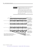
Insertion
1.
Disconnect power.
2.
Align the full-sized circuit board with the chassis card guides.
The first slot (slot 0) of the first rack is reserved for the SLC 500
processor.
3.
Slide the module into the chassis until the top and bottom
latches catch.
4.
Attach the RIO link cable to the connector on the front of the
module, behind the door. Ground the cable’s shield wire to a
chassis mounting bracket. See the RIO link wiring illustration on
page 2-4.
5.
Insert the cable tie in the slots.
6.
Route the cable down and away from module, securing it with
the cable tie.
7.
Cover all unused slots with the Card Slot Filler, Catalog Number
1746-N2.
ATTENTION
Disconnect system power before attempting to
install, remove, or wire the scanner.
IMPORTANT
Make sure you have set the DIP switches properly
before installing the scanner.
IMPORTANT
Before installation, ensure that your modular SLC
power supply has adequate reserve current capacity.
The scanner requires 600 mA @ 5V dc.
Artisan Technology Group - Quality Instrumentation ... Guaranteed | (888) 88-SOURCE | www.artisantg.com


