218
Rockwell Automation Publication 1715-UM001J-EN-P - December 2020
Chapter 7 1715 Redundant I/O System in SIL 2 Safety Applications
Simple Input-logic-output Chain
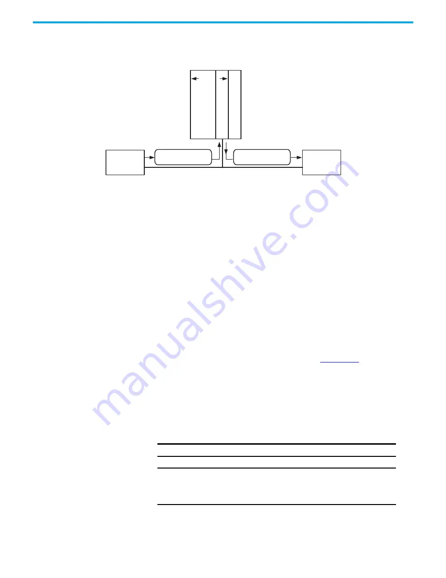
Figure 68 - Logix System Worst-case Reaction Time for Simple Input to Logic to Output
The Logix System Reaction Time for any simple input to logic to output chain
consists of these five components.
1. Safety input module reaction time plus input delay time
2. Safety Input Connection Reaction Time Limit
(Read from the Module Properties dialog box in RSLogix 5000 software.)
3. Safety Task Period plus Safety Task Watchdog time
4. Safety Output Connection Reaction Time Limit
(Read from the Module Properties dialog box in RSLogix 5000 software.)
5. Safety output module reaction time
Configuring the SIL 2 Task
Period and Watchdog
This SIL 2 task is a periodic task with priority (1). See the Using ControlLogix
SIL 2 Applications Reference Manual, publication
1756-RM001
.
SIL Task/Program Instructions
The user application must contain one SIL task that is composed of programs
and routines. The SIL 2 task must be the top priority task of the controller and
the user-defined watchdog must be set to accommodate the SIL 2 task.
The task period and task watchdog are configured in the Task Properties
dialog box.
1. Safety Input
Module Delay
5. Safety Output
Module Delay
2. Safety Input Connection
Reaction Time Limit
4. Safety Output Connection
Reaction Time Limit
CIP Safety Network
Co
mmu
nic
ation
Module
GuardLog
ix® C
ont
ro
ller
3. Safety Task
Safety Task Watchdog
IMPORTANT
Motion-related functions are not allowed and must not be used.
IMPORTANT
You must dedicate a specific task for safety-related functions
and set that task to the highest priority (1). SIL 2 safety logic and
logic that is intended for use in non-SIL 2 functions must be
separate.


