102
Rockwell Automation Publication 1715-UM001J-EN-P - December 2020
Chapter 2 Installation Instructions
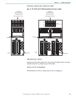
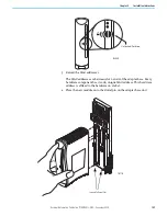
To install the 1715-AENTR adapters on to the 1715-A2A two-slot base unit, follow
these steps.
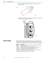
1. Inspect the connector pins.
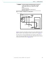
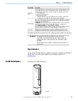
2. Inspect the identification labels on the sides of the adapters and record
the location and the module information that is shown on the label.
This helps you when installing a new or replacement module in the
future by allowing you to order the replacement parts without disturbing
the system.
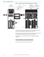
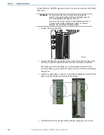
3. Check the coding pegs on the 1715-A2A adapter backplane and verify that
they match the sockets on the back of the adapter.
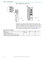
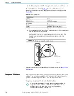
4. Verify that the slot on the head of the adapter clamp screw is vertical.
IMPORTANT
You must inspect the connector pins before you install the
modules. If you install modules with bent or damaged connector
pins, it can damage the backplane connectors.
Also, inspect the socket contacts on the backplane, and for an I/
O module, on the mating termination assembly. If a contact is
damaged, do not attempt to install the module.
32085a-M
32085 M

