Parameters and Programming
5-19
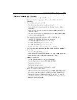
Common Problems with PI Control
1. Drive direction is incorrectly set for PI control.
Ensure that the drive is operating with the clockwise direction indicator
illuminated.
2. Drive oscillates between 0 and 3 Hz.
• Check direction and polarity of analog input signal.
• Ensure that the drive is operating with the clockwise direction indicator
illuminated.
• Ensure the +10V DC wire is connected to TB3-2 and that the common is
connected to TB3-3.
• Check that parameters
P81 - [PI Proportional Gain]
and
P82 - [PI Integral Gain]
are set to a value other than 0.00.
3. Drive accelerates too quickly resulting in an
F05 - OverVoltage Fault
.
• Lower
P81 - [PI Proportional Gain]
below its current value.
• Lower
P82 - [PI Integral Gain]
below its current value.
• Raise
P31 - [Decel Time 1]
above its current value.
• Raise
P30 - [Accel Time 1]
above its current value.
• Evaluate the need for a dynamic brake for the application.
4. Drive will only run off the internal frequency or does not control with the PI
process loop.
• Check that
P46 - [Input Mode]
is set to 9.
• Ensure that power was cycled for one minute after changing the P46 setting.
• Ensure that there is not a connection between TB3-7 and 8.
5. Nothing works properly.
• Set
P56 - [Reset Functions]
to 1 and press the Enter key.
• Press the Stop button to clear the
F48 - Reprogram Fault
.
• Cycle power to the drive.
• Confirm that wiring is correct.
• Reapply power and program according to this procedure.
6. PI does not function with DeviceNet.
• Firmware Version 7.05 and earlier only allows one
P46 - [Input Mode]
setting
to be active at one time (settings 2 or 6 for DeviceNet or setting 9 for PI).
• It is possible for users of Firmware Version 7.05 and earlier to set up PI
control via an external processor, such as a SLC500. Consult your processor
manual for specific instructions.
Summary of Contents for Allen-Bradley 160 SSC Series
Page 12: ...1 6 Getting Started End of Chapter ...
Page 58: ...5 20 Parameters and Programming End of Chapter ...
Page 66: ...A 4 Specifications End of Chapter ...
Page 75: ...Accessories and Dimensions B 9 Drilling Template A Figure B 10 ...
Page 76: ...B 10 Accessories and Dimensions Drilling Template B Figure B 11 ...
Page 82: ...C 6 CE Conformity End of Chapter ...
Page 87: ......


