Parameters and Programming
5-5
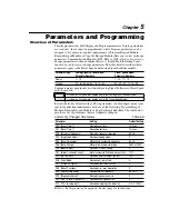
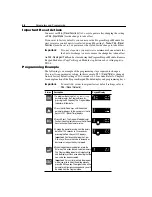
Program Group Parameters
This group contains parameters whose values
can
be programmed. Refer to
Programming Example
earlier in this chapter. Unless otherwise stated, parameters
that are programmed while the drive is running take immediate effect.
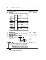
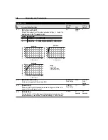
Display Group (Read Only)
No.
Parameter Name/Description
Min./Max. Range Units
17
[Fault Buffer 0]
This parameter stores the last fault that occurred. If the same fault occurs multiple times in
a row, it will be stored once. After a “reset defaults” (P56) this will set this parameter to
F48 - Reprogram Fault. As faults occur, the previous value of this parameter is moved to
P18 - [Fault Buffer 1].
0/48
Numeric Value
18
[Fault Buffer 1]
This parameter stores the second most recent fault that occurred. After a “reset defaults”
(P56) this will set this parameter to 0 (No active fault). As faults occur, the value of this
parameter will be overwritten by P17 - [Fault Buffer 0]. The previous value of this parameter
is moved to P19 - [Fault Buffer 2].
0/48
Numeric Value
19
[Fault Buffer 2]
This parameter stores the third most recent fault that occurred. After a “reset defaults” (P56)
this will set this parameter to 0 (No active fault). As faults occur, the value of this parameter
will be overwritten by P18 - [Fault Buffer 1].
0/48
Numeric Value
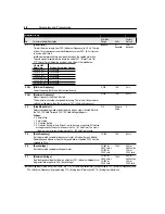
Program Group
No.
Parameter Name/Description
Min./Max.
Range
Units
Factory
Default
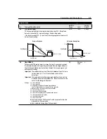
30
[Accel Time 1]
Time for the drive to ramp from 0.0 Hz. to P33 - [Maximum Frequency]. The rate
is linear for any increase in command frequency unless P53 - [S-Curve] is set to
a value other than “0”. Setting this to 0.0 sec. gives 0.1 sec acceleration with the
initial current limit turned off. This allows quicker acceleration times for low inertia
systems. For medium to high inertia systems, the minimum value should be 0.1
sec.
0.0/600.0
0.1
Seconds
10.0
Seconds
Speed
0
Time
Maximum
Frequency
Accel Time
Decel Time
0
Acceleration
Deceleration
Summary of Contents for Allen-Bradley 160 SSC Series
Page 12: ...1 6 Getting Started End of Chapter ...
Page 58: ...5 20 Parameters and Programming End of Chapter ...
Page 66: ...A 4 Specifications End of Chapter ...
Page 75: ...Accessories and Dimensions B 9 Drilling Template A Figure B 10 ...
Page 76: ...B 10 Accessories and Dimensions Drilling Template B Figure B 11 ...
Page 82: ...C 6 CE Conformity End of Chapter ...
Page 87: ......

