2-14
Installation and Wiring
Important:
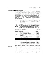
Settings 4 through 9 provide additional flexibility of TB3 control
input terminal 8.
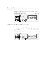
P46 Setting 4 - Two-Wire Accel/Decel Control
This input mode is similar to Setting 1 except TB3 terminal 8 provides the function
of switching from
P30 - [Accel Time 1]
and
P31 - [Decel Time 1]
to
P69 - [Accel Time 2]
and
P70 - [Decel Time 2]
for any commanded frequency reference.
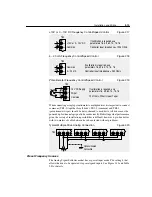
Two-Wire Accel/Decel control
Figure 2.8
➊
TB3 terminal 8 can be used to clear faults. See Figure 2.14 for details.
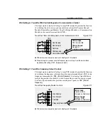
P46 Setting 5 - Two-Wire Enable Control
This input mode is similar to Setting 1 except TB3 terminal 8 provides the function
of “enable” command. The “enable” input is required for the drive to operate and
if opened during operation the programmed
P34 - [Stop Mode]
will be overridden
and the motor will coast to rest.
Two-Wire Enable control
Figure 2.9
➊
TB3 terminal 8 can be used to clear faults. See Figure 2.14 for details.
➋
When this input is in an open state, the motor will coast to rest.
56
7
8
Run Reverse
Run Forward
Common
Accel/Decel Select
➊
TB3
TB3-8 Open
Accel 2, Decel 2
TB3-8 Closed
Accel 1, Decel 1
Enable
➊
56
7
8
Common
Run Reverse
Run Forward
TB3
TB3-8 Open
Controller Disabled
➋
TB3-8 Closed
Controller Enabled
Summary of Contents for Allen-Bradley 160 SSC Series
Page 12: ...1 6 Getting Started End of Chapter ...
Page 58: ...5 20 Parameters and Programming End of Chapter ...
Page 66: ...A 4 Specifications End of Chapter ...
Page 75: ...Accessories and Dimensions B 9 Drilling Template A Figure B 10 ...
Page 76: ...B 10 Accessories and Dimensions Drilling Template B Figure B 11 ...
Page 82: ...C 6 CE Conformity End of Chapter ...
Page 87: ......


