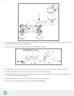
3. Connect the white, green and bare wires to the Robotiq RS-485 signal converter as shown in the figure below. Also connect the
red (24V) and black (0V) wires in the terminal blocks of the robot controller.
Fig. 3-2: Vacuum Gripper wiring to robot controller
4. Connect the USB cable into a USB port of the robot controller.
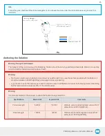
The figure below illustrates the Vacuum Gripper pigtail connector from the coupling (GRP-CPL-062 or AGC-CPL-XXX-002), the device
cable on the robot side (CBL-COM-2065-10-HF) and their associated pinout.
Fig. 3-3: Pinout of the Vacuum Gripper pigtail and device cable
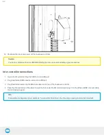
Box sensor
1. Via a hole under the UR controller, run the box sensor cable in and connect the brown (24V), blue (0V) and black (digital input)
wires.
44
Summary of Contents for PALLETIZING SOLUTION
Page 12: ...Palletizing Solution Instruction Manual 12...
Page 72: ...6 1 2 AirPick Vacuum Gripper Fig 6 1 AirPick general dimensions 72...
Page 73: ...Palletizing Solution Instruction Manual 6 1 3 Extra Reach Bracket 73...
Page 74: ...6 1 4 Bracket for two 2 Suction Cups Fig 6 2 Two air nodes bracket s dimensions 74...
Page 80: ...80...
Page 95: ...1 2 2 Safety Connections Fig 12 2 Universal Robots Controller Safety Connections Schema 95...

