


Robotiq 2-Finger Adaptive Robot Gripper - 200
Instruction Manual
Robotiq inc. © 2008-2013
17
1.
a.
b.
2.
3.
a.
3.3 Mechanical connections
You must use Robotiq's coupling to attach the Gripper to the robot. Be sure to use the coupling and optional
adapters related to your robot model. If there is no options for your robot, you can modify a blank adapter plate,
Robotiq can create a custom version for you or you can build one based on the dimensions in
. Please
refer to the
for a list of available coupling and adapters.
Here are the steps to follow for the installation of the Gripper (see Figure 3.3.1). Note that all screws must be locked
in place using medium strength thread locker (Loctite 248).
Attach the Coupling to the Gripper by aligning the indexing dowel pins with the associated holes
All dowel pins are 8 m6 x 20 standard stainless steel (
).
Ø
Y-997
Dowel pins must be press-fitted in the Coupling.
Secure the Gripper with coupling screws (socket head cap screws M8 x 40
).
Y-830
Screw the Coupling to your robot arm with the robot side screws (socket head cap screws M8 x 30
).
Y-829
With optional adapter plate : Screw the adapter plate to the robot arm and then your Coupling to the
adapter plate(if your cables are running through the robot, be sure to use an adapter plate with a
groove).
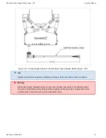
Figure 3.3.1 : Attaching the 2-Finger Adaptive Robot Gripper 200 to a robot arm with Robotiq coupling.
–
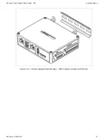
The 2-Finger Adaptive Robot Gripper 200 Controller Unit is equipped with DIN rail mounting clips and is designed
–
to be clipped on #3 DIN rails. It is recommended to fix the Controller Unit inside the robot controller cabinet.