SECTION 5: C
OMMUNICATIONS
39
Each control board on the network must have a
unique MAC address. The IP address must be
unique on the Ethernet network. The default IP
address can be used or a custom IP address can be
assigned. In addition to these two addresses, the IP
network number must be set for each controller. Use
the touchscreen provided to set these values.
The touchscreen communicates between controllers
over an MS/TP network with network number 100.
This must not be changed.
The MS/TP network
number is important for the broadcasting of Outside
Air Temperature.
Create the MS/TP network between controllers.
. Access the controller you wish
to program through the touchscreen home menu.
for help.
Default IP Address
IP address: 192.168.168.x where x is the MAC
address
Subnet mask: 255.255.255.0
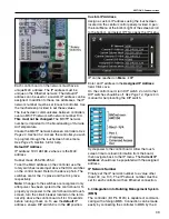
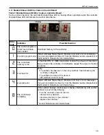
To set the MAC address on the controller, use the
rotary switches located just above the HOA switches
on the control board. Refer to the above photo. The
switches are for the 1's place and the 10's place
respectively.
Note:
Changes to the switches are recognized only
after power has been cycled to the control board. To
properly cycle power to the control board and touch-
screen, turn the circuit breaker located on the termi-
nal strip above the control board off for 10 seconds
before turning it back on. To use the
default
IP
address, ensure DIP switch 2 is in the
off
position.
Custom IP Address
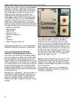
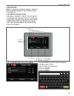
Assign a custom IP address using the touchscreen
located on the central control panel provided. Open
the local Menu at the bottom right of the screen scroll
to the bottom, and select IP. This opens the IP menu.
IP can be reached on
Menu
IP
Enter an IP address in the
Assigned IP Address
field. Click save.
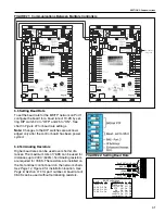
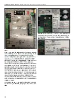
On the control board, turn DIP switch 2 on. All other
DIP switches should be off.
manual for help locating the DIP switch.
Cycle power to the control board. Allow the touch-
screen time to reload information from the board,
then navigate back to the IP menu. The
Current IP
Address
should now be populated with the assigned
address.
IP Network Number
Finally, set the IP network number to a value other
than 100 (i.e. 101). The IP network number must be
set for each controller with an Ethernet connection.
5.3 Integration into Building Management System
(BMS)
The controller (I/O Pro 812U) is capable of communi-
cating with a foreign BMS. Connection can be made
easily by connecting the controller to BMS by the 2-
Summary of Contents for CORAYVAC
Page 2: ......
Page 4: ......
Page 69: ...SECTION 8 PROGRAMMING AND TROUBLESHOOTING THE SYSTEM 65 THIS PAGE LEFT INTENTIONALLY BLANK ...
Page 71: ...SECTION 9 TROUBLESHOOTING 67 FIGURE 26 Vacuum pump does not turn on ...
Page 75: ...SECTION 9 TROUBLESHOOTING 71 FIGURE 31 Burner troubleshooting in manual mode ...
Page 77: ...SECTION 9 TROUBLESHOOTING 73 After 45 second prepurge burners do not light continued ...
Page 81: ...SECTION 9 TROUBLESHOOTING 77 FIGURE 36 Air Pressure Switch alarm ...
Page 83: ...SECTION 9 TROUBLESHOOTING 79 FIGURE 38 Repeater troubleshooting ...
Page 85: ...SECTION 9 TROUBLESHOOTING 81 BACnet MS TP troubleshooting continued ...
Page 109: ...SECTION 13 TOUCHSCREEN TREE 105 Touchscreen Tree Overview continued ...
Page 111: ...SECTION 13 TOUCHSCREEN TREE 107 FIGURE 47 Maintenance Unit FIGURE 48 Alarms ...
Page 113: ...SECTION 13 TOUCHSCREEN TREE 109 FIGURE 51 Configuration Zones FIGURE 52 Configuration Unit ...
Page 115: ...SECTION 13 TOUCHSCREEN TREE 111 FIGURE 55 Touchscreen System FIGURE 56 Touchscreen Setup ...
Page 118: ...ROBERTS GORDON CORAYVAC MODULATING HEATING CONTROL CONTROLLER INSTALLATION MANUAL 114 ...

