background image

CRV-S

ERIES

 I

NSTALLATION

, O

PERATION


AND

 S

ERVICE

 M

ANUAL

74 of 83

SECTION 17: TROUBLESHOOTING

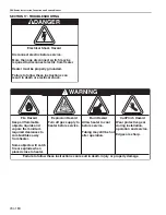
DANGER

Electrical Shock Hazard

Disconnect electric before service.

More than one disconnect switch may be 
required to disconnect electric from heater.

Heater must be properly grounded.

Failure to follow these instructions can 
result in death or electrical shock.

Fire Hazard

Keep all flammable 
objects, liquids and 
vapors the minimum 
required clearances to 
combustibles away 
from heater.

Some objects will catch 
fire or explode when 
placed close to heater.

Cut/Pinch Hazard

Wear protective gear 
during installation, 
operation and service.

Edges are sharp.

WARNING

Failure to follow these instructions can result in death, injury or property damage.

Burn Hazard

Allow heater to cool 
before service.

Tubing may still be hot 
after operation.

Explosion Hazard

Turn off gas supply to 
heater before service.

Summary of Contents for CoRayVac CRV-B-10

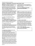
Page 1: ...ms Installation Operation Service Manual WARNING FOR YOUR SAFETY If you smell gas 1 Open windows 2 DO NOT try to light any appliance 3 DO NOT use electrical switches 4 DO NOT use any telephone in your building 5 Extinguish any open flame 6 Leave the building 7 Immediately call your local gas supplier after leaving the building Follow the gas supplier s instructions 8 If you cannot reach your gas s...

Page 2: ......

Page 3: ... Outside Air Blower Internal Wiring 44 SECTION 11 Gas Piping 47 SECTION 12 Control Methods 49 12 1 ROBERTS GORDON System Control 49 12 2 ROBERTS GORDON ULTRAVAC 49 12 3 CORAYVAC Modulating Controls 49 12 4 SPST Transformer Relay Kit P N 90417600K 52 12 5 SPDT Transformer Relay P N 90436300 52 SECTION 13 Starting The System 63 13 1 Checking the Gas Line 63 13 2 Checking the Electrical System 63 13 ...

Page 4: ......

Page 5: ... Air Supply 46 Figure 27 Non Pressurized Outside Air Supply 46 Figure 28 Gas Connection with Flexible Gas Hose 48 Figure 29 VFD Terminal Strip 51 Figure 30 One Zone Operation without Control Panel optional 53 Figure 31 One Zone Operation with Outside Air Blower without Control Panel optional 54 Figure 32 Two Zone Operation without Control Panel optional 55 Figure 33 General System Wiring 56 Figure...

Page 6: ......

Page 7: ... compatible This heater must be applied and operated under the general concepts of reasonable use and installed using best building practices This appliance is not intended for use by persons including children with reduced physical sensory or mental capabilities or lack of experience and knowledge unless they have been given supervision or instruction concerning use of the appliance by a person r...

Page 8: ...Plate Label Logo Label Clearances to Combustibles Label Control Side Panel inside Filter Side Panel inside Wiring Label Internal Ladder Diagram Label Description Part Number Logo Label 91007901 Rating Plate Label 91010401 Clearances to Combustibles Label 91009101 Internal Ladder Diagram Label 91017301 Wiring Label 91017300 ...

Page 9: ...SECTION 1 HEATER SAFETY 3 of 83 FIGURE 2 Top and Back Panel Label Placement Description Part Number Gas Connection Label 91018125 Burner Box Combination Label 91029600 Proposition 65 Label 91070016 ...

Page 10: ...he CRV Series heater e g thermostat or controller A copy of the wall tag P N 91037912 is illustrated on the back cover For an immediate solution you may affix this copy on the wall near the heater Know your model number and installed configuration Model number and installed configuration are found on the burner and in the Installation Operation and Service Manual See Page 6 Figure 3 through Page 8...

Page 11: ...lity to assure that adjacent materials are protected from degradation Maintain clearances from heat sensitive equipment and workstations Maintain clearances from vehicles parked below the heater Maintain clearances from swinging and overhead doors overhead cranes vehicle lifts partitions storage racks hoists building construction etc In locations used for the storage of combustible materials signs...

Page 12: ...RV B 12 4 36 60 36 11 92 153 92 CRV B 12A 4 36 60 36 11 92 153 92 B C D A FIGURE 4 ONE SIDE REFLECTOR inches centimeters Model A B C D A B C D CRV B 2 4 12 56 20 11 31 143 51 CRV B 4 4 12 56 20 11 31 143 51 CRV B 6 4 12 56 20 11 31 143 51 CRV B 8 4 12 56 20 11 31 143 51 CRV B 9 4 12 60 42 11 31 153 107 CRV B 10 4 12 60 42 11 31 153 107 CRV B 12 4 12 60 42 11 31 153 107 CRV B 12A 4 12 60 42 11 31 1...

Page 13: ...4 18 21 46 61 46 CRV B 12A 8 18 24 18 21 46 61 46 C A B D FIGURE 7 UNIVERSAL SHIELD POSITION 2 inches centimeters Model A B C D A B C D CRV B 2 4 24 48 24 11 61 122 61 CRV B 4 4 24 48 24 11 61 122 61 CRV B 6 4 24 48 24 11 61 122 61 CRV B 8 4 24 48 24 11 61 122 61 CRV B 9 4 36 48 36 11 92 122 92 CRV B 10 4 36 48 36 11 92 122 92 CRV B 12 4 36 48 36 11 92 122 92 CRV B 12A 4 36 48 36 11 92 122 92 C A ...

Page 14: ...6 143 46 CRV B 12 4 18 56 18 11 46 143 46 CRV B 12A 4 18 56 18 11 46 143 46 A B C D FIGURE 10 BARRIER SHIELD inches centimeters Model A B C D A B C D CRV B 2 4 12 12 12 11 31 31 31 CRV B 4 4 12 12 12 11 31 31 31 CRV B 6 4 12 12 12 11 31 31 31 CRV B 8 4 12 12 12 11 31 31 31 CRV B 9 UNAPPROVED UNAPPROVED CRV B 10 UNAPPROVED UNAPPROVED CRV B 12 UNAPPROVED UNAPPROVED CRV B 12A UNAPPROVED UNAPPROVED C ...

Page 15: ...ovisions shall be made to assure accessibility to suspended heaters for recurrent maintenance purposes 4 3 Public Garages Installation in garages must be in accordance with the following codes United States Refer to Standard for Parking Structures NFPA 88A latest revision or the Code for Motor Fuel Dispensing Facilities and Repair Garages NFPA 30A latest revision Canada Refer to Natural Gas and Pr...

Page 16: ...ll appropriate suspension hardware beam clamps chain or rod at predetermined locations Adjustments of chain length will provide uniform pitch FIGURE 12 Major Component Descriptions Burner Tube Hot rolled heat treated or coated aluminized tube supplied in 10 3 m lengths 45 Elbow 90 Elbow End Vent Coupling Assembly with Lock Flex Gas Line with shut off cock Combustion Chamber Tee Reflector Aluminum ...

Page 17: ...tension Bracket Barrier Shield Reflector Side Extension Condensate Valve Assembly Reflector End Cap Aluminum or Stainless Steel Punch out center section to accommodate tube S Hook Deco Grille Turnbuckle Protective Grille Universal Shield Tube and Reflector Hanger Suspend system from these hangers Reflector Support Strap Wire Form Bracket Assembly ...

Page 18: ...treet West Unit 10 Grims by Ontario L3M 1R6 Canad a Telephone 905 945 5403 Fax 905 945 0511 Printe d in U S A Impri mé aux Etats Unis P N 91008 005 Rev B ROBERTSGORDON UltraVac Controller Part Number Numéro de la Pièce ENCLO SED ENERG Y MANAG EMENT EQUIP MENT 58SB Serial Number No de Série Ratings Input 120V AC 25A Outputs 120V AC 3A 8 total EP 100 Pump Package 4 dia For more information refer to ...

Page 19: ...zed 6 15 cm dia 10 3 m 9141030D Tube Coated 4 10 cm dia 10 3 m E0009105 Tube Heat Treated Aluminized 6 15 cm dia 10 3 m Part No Description 91418200 Tube Adapter Aluminized 6 15 cm dia x 4 10 cm dia 02722100 Adapter 4 10 cm Cast Iron 02726000K Lower Tube Temperature Insert 91240010 Tube Hanger 6 15 cm 91308001 High Temperature Pipe Compound 1lb can Part No Description Venting Accessories 01324401 ...

Page 20: ...2451 Voltage Surge Suppressor 120 V 90602452 Voltage Surge Suppressor 120 240 V 1 Ø 60 Hz 90602460 Line Reactor 480 V 3 Ø 60 Hz w Enclosure Output 90602461 Line Reactor 230 V 3 Ø 60 Hz 75 HP Output 90602462 Line Reactor 230 V 3 Ø 60 Hz 2 HP Output 90602470 Line Reactor 480 V 3 Ø 60 Hz 4 A w Enclosure Input Part No Description Thermostats 05023000 Load Relay Package 90417600K Transformer Relay SPST...

Page 21: ...ensate Neutralization Tube 600 01327004 Condensate Neutralization Tube 1000 01327005 Condensate Neutralization Tube 2000 01327007 Refill Condensate Neutralization Tube 600 01327008 Refill Condensate Neutralization Tube 1000 01327009 Refill Condensate Neutralization Tube 2000 Part No Description Contactors 10050011 Contactor 120 Vac for EP 203 EP 303 3 Ø EP 100 EP 201 208 230 V 1 Ø EP 301 208 230 V...

Page 22: ...o the system operation and performance required by the building being heated Every effort should be made to follow the dimensions on the layout drawing If deviations are necessary either contact the company responsible for the layout design your ROBERTS GORDON independent distributor or consult the CRV Series Design Manual P N 127500NA ...

Page 23: ...ion Cet appareil doit être connecter à une source de courant avec mise á terre Faute de suivre ces instructions peut entraîner la mort ou les choc électriques Roberts G ordon P O Box 44 Buffalo NY 14240 004 4 Telephone 716 852 4 400 Fax 716 852 0 854 Toll Free 800 828 7 450 www rg in c com Roberts G ordon 76 Main Street West Unit 10 Grimsby Ontario L3M 1R6 Canada Telephone 905 945 54 03 Fax 905 94...

Page 24: ... as indicated on the rating plate and in this instruction manual The minimum and maximum gas inlet pressures must be maintained as indicated on the rating plate Typical installation configurations are shown on Page 19 Figure 14 Expansion and contraction of the tube dictates that the minimum suspension lengths must be maintained See table on Page 19 Figure 14 WARNING Severe Injury Hazard Secure bur...

Page 25: ... Hook 3 8 24 min 61 cm X See Table Locknut Typical Anchor Hanger Front View S Hook Turnbuckle Reflector 7 6 2 3 m Chain size 3 16 minimum Description Part Number Turnbuckle 91903201 S Hook 91907302 Tube Reflector Hanger 03090100 Run Length Typical Expansion Minimum X Length 50 15 m 1 3 cm 12 30 cm 100 31 m 2 5 cm 24 61 cm 150 46 m 3 8 cm 36 91 cm 200 61 m 4 10 cm 46 122 cm 250 76 m 5 13 cm 57 145 ...

Page 26: ... Seam Bottom of Tube Hanger Turnbuckles Tube Description Part Number Tube 91409XXX Turnbuckle 91903201 Tube Reflector Hanger 03090100 Tube Tube Orient coupling so that the impact block is in the 2 00 or 10 00 o clock positions Closed Open Tab 3 8 cm to 4 10 cm Slide Bar Coupling Lock Coupling Wide End Coupling Tube Slide Bar Coupling Lock A Close coupling with tab B Start slide bar coupling lock o...

Page 27: ...eat Step 7 2 A D until all tubes are assembled NOTE If coupling is not tight loss of vacuum can occur Tighten slide bar as shown below Tube 90 Elbow Coupling Description Part Number Elbow Package 02718702 90 Elbow 01335801 Coupling 01312700 Reflector End Cap 02750800 Reflector Joint Piece 02750900 U Clip Package 91107720 Minimum Distance Required Between Burner and Elbow Model MinimumDistance CRVB...

Page 28: ... and support strap Reflector must not touch tube Failure to follow these instructions can result in death injury or property damage Tube Hanger Combustion Chamber Slide Reflector with hole through hanger Unhook combustion chamber from chain and insert through hole Reconnect chain Reflector with Hole Description Part Number Tube Reflector Hanger 03090100 Tube 91409XXX Reflector with Hole 02750304 ...

Page 29: ... 2 Reflector Installation Reflector Wire Form Tube Reflector Support Strap Sheet Metal Screw U Clip 2 Clips per Alternate Overlaps per Side Description Part Number Reflector Support Package 03050010 U Clip Package 91107720 Reflector End Cap 027508XX ...

Page 30: ...sing a reflector support with loose screws at the reflector overlap 3 The remaining reflector overlaps require a non slip overlap connection To affix the reflectors together in a non slip overlap either a use reflector support and tight screws b if both reflectors lay inside a hanger u clips or sheet metal screws may be used This section of three reflectors joined together must be affixed to the t...

Page 31: ...ket Burner Combustion Chamber End Vent NOTE Install end vent at end combustion chamber position only Burner Combustion Chamber End Vent End Vent Clips Rating Number Description Part Number Bolt 94273914 Burner 0270XXXX Lock Washer 96411600 Gasket 01367800 End Vent 013676XX ...

Page 32: ...ep 8 1 Tee Installation WARNING Cut Pinch Hazard Wear protective gear during installation operation and service Edges are sharp Failure to follow these instructions can result in injury Tee Tube Coupling Description Part Number Tee 01330XXX Tube Reflector Hanger 03090100 Tube 91409XXX Coupling 01312700 ...

Page 33: ...SECTION 8 OPTIONAL HEATER ACCESSORIES 27 of 83 Step 8 2 Reflector Joint Step 8 2 1 Reflector Joint Installation Step 8 2 2 Reflector Joint Installation ...

Page 34: ...CRV SERIES INSTALLATION OPERATION AND SERVICE MANUAL 28 of 83 Step 8 2 3 Reflector Joint Detail FIGURE 15 Reflector Joint Detail ...

Page 35: ... air movement applications Tube and Reflector Hanger Reflector Tube Reflector Support Description Part Number Reflector Side Extension Package 02712700 Reflector Side Extension 01368000 Retainer Clips 02751200 Sheet Metal Screws 94118106 Order Separately Reflector Side Extension Bracket 01329910 Retainer Clip 2 per Side Cut relief notches for supports and hangers Reflector Side Extension 8 x 3 8 3...

Page 36: ...cket Assembly 02721400 Stud 02790900 Hex Nut 92114800 Universal shields are adjustable aluminum reflectors whose angle and height can be adjusted to direct heat to or away from a desired area See Page 7 Figure 6 through Page 7 Figure 8 for positions Reflector Support Strap Cut Relief Notch Flatten Reflector Edges Attach U Clips Tube and Reflector Hanger Standard Reflector Barrier Shield Descriptio...

Page 37: ... Grille Installation Step 8 6 2 Frame Shield Installation Suspended Ceiling Frame Heat Exchanger Tube 2 x 4 60 cm x 120 cm Aluminum Grille Reflector Tube and Reflector Hanger Description Part Number Aluminum Grille 2 x 4 60 cm x 120 cm 91407000 Shield Description Part Number Deco Grille Shield 01365900 ...

Page 38: ...siderable air movement it is recommended that one 8 x 3 8 sheet metal screw be installed per reflector extension to prevent it from blowing over Allow 6 15 cm minimum clearance between burner box and overhead obstructions for service 6 15 cm Minimum Insert screw here see note Distance A Extension Minimum Maximum Part No Width 2 4 cm 6 15 cm 01370408 8 20 cm 6 15 cm 10 26 cm 01370412 12 30 cm 10 26...

Page 39: ...tion Step 8 7 2 Grille End Cap Installation Step 8 7 3 Grille Installation Silicone Cap Grille Finger Description Part Number Grille Section 08050001 Grille End Cap 08050002 Silicone Cap 91915951 6P Bend up 90 Pull outward Grille Grille End Cap A B C D Grille Grille End Cap Reflector Final Grille Section 40 101 cm ...

Page 40: ...BERTS GORDON End Vent Plate for End Burner Only End Vent Clips Special Tube and Reflector Hanger ROBERTS GORDON End Vent Clips CORAYVAC Classic Turnbuckle Hang cast iron combustion chamber with a turnbuckle spring clips will not fit around cast iron hanging loop WARNING Severe Injury Hazard Hang heater with materials with a minimum working load of 750 lbs 340 kg Use special tube and reflector hang...

Page 41: ...P 200 Condensate Valve Assembly WARNING Carbon Monoxide Hazard Heaters installed unvented must be interlocked with sufficient building exhaust Heaters must be installed according to the installation manual Failure to follow these instructions can result in death or injury WARNING Cut Pinch Hazard Wear protective gear during installation operation and service Edges are sharp Failure to follow these...

Page 42: ... total condensate is 1 8 gal h the condensate neutralization tube which is closest to and higher than the calculated gal h value is P N 01327002 NOTE Condensate neutralization tubes must be replaced yearly every 2000 operating hours or check condensate water pH level If it is below pH 6 replace tube To order replacement see the chart below Radiant Tube Length average distance between burners Tailp...

Page 43: ... at a height sufficient to prevent blockage by snow and building materials protected from degradation by flue gases Secure all joints with 8 x 3 8 sheet metal screws Seal all joints with high temperature silicone sealant Vent terminal must be beyond any combustible overhang 9 2 1 United States Requirements Vent must terminate at least 3 0 9 m above any forced air inlet located within 10 3 1 m Vent...

Page 44: ...tional heat exchanger lengths are considered as vent length for length determination Subtract 15 4 6 m of maximum allowed vent or outside air duct length per vent elbow if more than three are used 9 2 6 Vent Material Recomendations Vent recommendations in order of preferred use 1 Porcelain coated tubing 4 10 cm O D P N 9141030D 2 Heat treated aluminized tubing 4 10 cm O D P N 91409408 Heat treated...

Page 45: ... dia 10 3 m 01335801 Elbow 4 10 cm Aluminized 90 91412800 Flexible Boot 4 10 cm 02718851 Drain Cap 4 10 cm 91412801 4 Flexible Boot 1 2 1 3 cm 02718852 Drain Cap Assembly 6 15 cm 91412802 Flexible Boot 6 15 cm 01327002 Condensate Neutralization Tube 200 91901300 Boot Clamp 4 10 cm 01327003 Condensate Neutralization Tube 600 91913703 Boot Clamp 6 15 cm 01327004 Condensate Neutralization Tube 1000 E...

Page 46: ...mber Description Part Number Description 01330203 Tee 4 10 cm Aluminized 01327005 Condensate Neutralization Tube 2000 01331900 Damper Coupling 4 10 cm 90502100 Vent Terminal 4 10 cm Combustible Wall 01335801 Elbow 4 10 cm Aluminized 90 90502101 Vent Terminal 6 15 cm Combustible Wall 01365400 Bird Screen 4 10 cm 91409403 Tube Aluminized 4 10 cm dia 10 3 m 02537801 1P Vent Terminal Non Combustible W...

Page 47: ...ption Part Number Description 01330203 Tee 4 10 cm Aluminized 90502101 Vent Terminal 6 15 cm Combustible Wall 01331900 Damper Coupling 4 10 cm 91409403 Tube Aluminized 4 10 cm dia 10 3 m 01335801 Elbow 4 10 cm Aluminized 90 91409420 Tube Aluminized 6 15 cm dia 10 3 m 01365400 Bird Screen 4 10 cm 91412801 4 Flexible Boot 1 2 1 3 cm 02537801 1P Vent Terminal Non Combustible Wall 91418200 Tube Adapte...

Page 48: ...nized 90502101 Vent Terminal 6 15 cm Combustible Wall 01331900 Damper Coupling 4 10 cm 90502302 Vent Cap 6 15 cm Metalbestos 01335801 Elbow 4 10 cm Aluminized 90 91409403 Tube Aluminized 4 10 cm dia 10 3 m 01397400 Bird Screen 6 15 cm 91409420 Tube Aluminized 6 15 cm dia 10 3 m 02537801 1P Vent Terminal Non Combustible Wall 91412800 Flexible Boot 4 10 cm 02718851 Drain Cap 4 10 cm 91412802 Flexibl...

Page 49: ... series with the pump pressure switch When using an outside air blower with a ROBERTS GORDON System Control or ROBERTS GORDON ULTRAVAC control or relay transformer a separate load relay package is required Wire the control for the relay in parallel with the pump The outside air blower must have a separate 20 A 120 V power supply See Page 44 Figure 23 for outside air blower internal wiring requirem...

Page 50: ...ments end vents When a duct is carrying more than 40 flow units it must be at least 6 15 cm diameter Pressurized Systems 6 15 cm diameter duct must not exceed 120 36 m total per system 4 10 cm diameter duct must not exceed 120 36 m per radiant branch Non Pressurized 6 15 cm diameter duct must not exceed 90 27 m maximum 100 flow units 4 10 cm diameter duct must not exceed 90 27 m Elbows are equival...

Page 51: ...pport Clamp Description Part Number Filter Housing 01326801 Filter and Gaskets 01312401 Filter Support 91905500 Wing Nut 92511601 4 10 cm Air Flex Duct box of eight 8 2 4 m sections 91409601 Wall Outside Air Supply Blower Outside Wall 5 12 5 cm Inlet Pipe 5 12 5 cm Outlet Pipe Bird Screen or Vent Cap Description Part Number Blower 90707501K 5 12 7 cm Vent Cap 90502302 6 15 cm Bird Screen 01397400 ...

Page 52: ...using 01326801 4 10 cm Take Off 01324401 Blower 90707501K 5 12 7 cm Vent Cap 90502301 6 15 cm Bird Screen 01365400 6 15 cm Band Clamp 91913703 Vent Cap Outside Wall 7 16 11 1 mm Diameter Hole Pressure Switch Lock Nuts 6 1 8 m Maximum Bird Screen or Description Part Number Pressure Switch Kit 90434501 4 10 cm Bird Screen 01365400 4 10 cm Vent Cap 90502300 6 15 cm Vent Cap 90502302 ...

Page 53: ...hen gas piping is not included in the layout drawing the local gas supplier will usually help in planning the gas piping Gas lines must meet applicable codes United States The Flexible Stainless Steel Gas Hose US models supplied with the heater is certi fied per the Standard for Connectors for Gas Appli ances ANSI Z21 24 CSA 6 10 latest revision Canada The Rubber Type 1 Gas Hose Canadian models op...

Page 54: ...e Gas Hose 36 91 cm length 3 8 cm max displacement Side View Heater Movement 12 30 cm CAUTION Product Damage Hazard Hold gas nipple securely with pipe wrench when attaching gas hose Failure to follow these instructions can result in product damage Description Part Number 1 2 Flexible Stainless Steel Gas Hose US Models 91412200 3 4 Flexible Stainless Steel Gas Hose US Models 91412204 1 2 Rubber Typ...

Page 55: ...ewed and altered from a PC not supplied running ROBERTS GORDON ULTRAVAC Software ROBERTS GORDON ULTRAVAC Software requires a PC not supplied running Windows 95 or higher with a Pentium class processor and at least 64k of RAM For complete installation details please refer to the ROBERTS GORDON ULTRAVAC Installation Operation and Service Manual P N 10081601NA latest revision Special design requireme...

Page 56: ...at wiring See Page 59 Figure 37 and Page 60 Figure 38 An optional room sensor P N 10081520 and outdoor air sensors P N 10081521 are available for this thermostat as well The modulating thermostat with LonWorks provides networking capability in a LonWorks system With communications port running at 78 kilobits per second kbs this thermostat can be configured to perform a variety of activities in whi...

Page 57: ...thermostat wiring diagram is shown on Page 59 Figure 37 When the temperature falls below the setpoint the modulating thermostat will generate a demand signal to the VFD The VFD will output a signal to the pump to run at the desired heater s firing rate There are two means to set up the analog signal from the modulating thermostat to the VFD See Page 51 Figure 29 1 To obtain 4 20 mA signal connect ...

Page 58: ... is a 120 V AC 20 A supply The transformer 24 V AC output for the thermostat is rated at 40 V A Thermostats used with the transformer must not exceed this power requirement A transformer relay operated system will not give any post purge pump operation to completely exhaust products of combustion from the system or provide indication of operating conditions 12 5 SPDT Transformer Relay P N 90436300...

Page 59: ...SECTION 12 CONTROL METHODS 53 of 83 FIGURE 30 One Zone Operation without Control Panel optional Description Part Number SPST Transformer Relay 90417600K ...

Page 60: ...CRV SERIES INSTALLATION OPERATION AND SERVICE MANUAL 54 of 83 FIGURE 31 One Zone Operation with Outside Air Blower without Control Panel optional ...

Page 61: ...SECTION 12 CONTROL METHODS 55 of 83 FIGURE 32 Two Zone Operation without Control Panel optional Description Part Number SPDT Transformer Relay 90436300 ...

Page 62: ...CRV SERIES INSTALLATION OPERATION AND SERVICE MANUAL 56 of 83 FIGURE 33 General System Wiring FIGURE 34 External Wiring Diagram EP 100 and EP 201 120 V 1 Ø Pump ...

Page 63: ...IGURE 35 External Wiring Diagram EP 100 EP 201 or EP 301 230 V 1 Ø Pump optional CAUTION Product Damage Hazard Do not directly connect control relay terminals to pump motor Failure to follow these instructions can result in product damage ...

Page 64: ...58 of 83 FIGURE 36 External Wiring Diagram EP 203 or EP 303 208 230 V or 460 V 3 Ø Pump optional CAUTION Product Damage Hazard Do not directly connect control relay terminals to pump motor Failure to follow these instructions can result in product damage ...

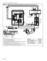
Page 65: ...ing Wiring Diagram LonWorks 2 10 Vdc with 500 ohm resistor optional Description Part Number SPST Transformer Relay 90417600K Thermostat Modulating LonWorks 90425104 Thermostat Modulating 90425105 Sensor Remote Modulating 10081520 Sensor Outdoor Modulating 10081521 ...

Page 66: ...GURE 38 CORAYVAC Modulating Wiring Diagram LonWorks 4 20 mA optional Description Part Number SPST Transformer Relay 90417600K Thermostat Modulating LonWorks 90425104 Thermostat Modulating 90425105 Sensor Remote Modulating 10081520 Sensor Outdoor Modulating 10081521 ...

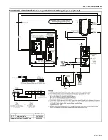
Page 67: ...SECTION 12 CONTROL METHODS 61 of 83 FIGURE 39 CORAYVAC Modulating with BACnet Wiring Diagram optional Description Part Number SPST Transformer Relay 90417600K Thermostat Modulating BACnet 90425109 ...

Page 68: ... with wiring material having a temperature rating of at least 105 C and 600 volts FIGURE 41 Burner Internal Ladder Diagram S1 TRANSFORMER VALVE GAS 120 V Power Supply Yellow Yellow Brown Green White Black 3 4 1 5 BURNER IGNITION MODULE Black Blue Yellow V2 GND TH V1 Green Gap TRANSFORMER L1 L2 Black White Blue Yellow Brown ELECTRODE GAS VALVE V2 Gnd S1 V1 TH Black Yellow IGNITION MODULE ...

Page 69: ...ately 3 5 wc or slightly above cold 13 3 Starting the System NOTE During the initial firing the protective oil on the tubing may smoke for 30 to 60 minutes and adequate ventilation should be provided 1 Start with all temperature setpoints below room temperature 2 Open main gas valve 3 Turn up temperature setpoints one zone at a time waiting to see that all burners in a zone start When the burner i...

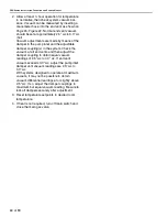
Page 70: ...in the system Check the vacuum at all end vents and then adjust the damper coupling to obtain equal vacuum readings of 2 5 wc to 3 0 wc If end vent vacuum exceeds 3 0 wc adjust the pump inlet damper until vacuum readings are 2 5 wc to 3 0 wc With systems designed to operate at maximum vacuum it may not be possible to obtain vacuum differential readings at or slightly above 2 5 wc If so adjust the ...

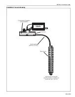
Page 71: ...SECTION 13 STARTING THE SYSTEM 65 of 83 FIGURE 42 Vacuum Reading ...

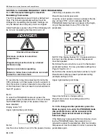
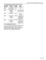
Page 72: ...ay will read P01 which indicates that the PROGRAM mode has been accessed at the begin ning of the parameter menu P01 is the first parameter NOTE If the display flashes Er the password was incorrect and the process to enter the password must be repeated 14 1 3 Use the arrow buttons to scroll to the desired parameter number For new parameter settings See Page 67 Section 14 2 14 1 4 Once the desired ...

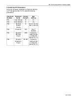
Page 73: ...following parameters Parameter Number Parameter Name Factory Default New Setting P01 Line Voltage 01 01 P03 Start Method 01 05 P05 Standard Speed Source 01 03 0 10 Vdc 04 4 20 mA P44 Password 225 Any 000 999 P45 Speed at Minimum Signal 0 0Hz Frequency Setting noted on Page 68 Section 15 2 2 P46 Speed at Maximum Signal 60 0Hz Frequency Setting noted on Page 68 Section 15 2 1 ...

Page 74: ...60 0 hit the up arrow button on the VFD until the number reads 60 0 Let the burners fire for approximately 20 30 minutes to warm up the system Using a manometer check the end vent vacuum in each zone each branch of burners See Page 70 Figure 43 If the lowest end vent vacuum reading is above 3 0 wc reduce the vacuum pump speed Generally the lowest end vent vacuum reading is on the longest branch of...

Page 75: ...n the VFD Turn on the transformer relay and program the modulating thermostat to the customer s requirements Parameter Number Parameter Name Factory Default New Setting P01 Line Voltage 01 01 P03 Start Method 01 05 P05 Standard Speed Source 01 03 0 10 Vdc 04 4 20 mA P44 Password 225 Any 000 999 P45 Speed at Minimum Signal 0 0Hz Frequency Setting noted on Page 68 Section 15 2 2 P46 Speed at Maximum...

Page 76: ...0 of 83 FIGURE 43 Possible Damper Couplings Locations Damper Coupling Damper NOTE Damper setting will vary Zone 1 Zone 2 Zone 3 Zone 1 End Vent Zone 3 End Vent Zone 2 End Vent Zone 1 Damper Coupling Zone 2 Damper Coupling Zone 3 Damper Coupling Pump Damper ...

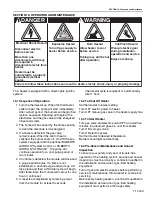
Page 77: ...t to lowest setting Turn OFF electric power to heater Turn OFF manual gas valve in the heater supply line 16 3 To Start Heater Turn gas valve and electric power OFF and wait five minutes for unburned gases to vent from heater Turn ON main gas valve Turn ON electric power Set thermostat to desired temperature Burner should light automatically 16 4 Pre Season Maintenance and Annual Inspection To ens...

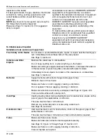
Page 78: ...Immediately remove these items if they are present See Page 5 Section 3 Vehicles and Other Objects Maintain the clearances to combustibles Do not hang anything from or place anything on the heater Make sure nothing is lodged underneath the reflector in between the tubes or in the decorative or protective grilles included with select models Immediately remove objects in violation of the clearances ...

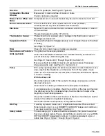
Page 79: ...ctly and secured in place if necessary Decorative grille only See Page 31 Section 8 6 2 Pump With pump operating check for excessive vibration or noise Vibration is usu ally a sign that the impeller is out of balance Turn off the system insure power is shut off and remove the inlet plate Check the shaft seal and replace it if worn or missing With the Power off Check the inlet and outlet of the pum...

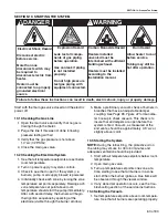
Page 80: ...ical shock Fire Hazard Keep all flammable objects liquids and vapors the minimum required clearances to combustibles away from heater Some objects will catch fire or explode when placed close to heater Cut Pinch Hazard Wear protective gear during installation operation and service Edges are sharp WARNING Failure to follow these instructions can result in death injury or property damage Burn Hazard...

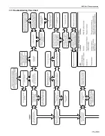
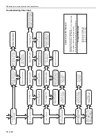
Page 81: ...SECTION17 TROUBLESHOOTING 75 of 83 17 1 Troubleshooting Flow Chart ...

Page 82: ... the end vent Is the vacuum setting too low Is the flame low Are the filters on the burners dirty Is the rotation of the pump motor correct Adjust system for proper vacuum at the end vent Follow burner check procedure given above Are there any dead burners in a branch Is the vacuum setting too low Is the system leaking water Do the burners lockout intermittently Yes Make sure that all thermostats ...

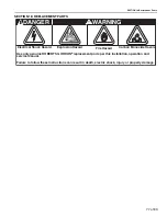
Page 83: ...oxide Hazard WARNING Use only genuine ROBERTS GORDON replacement parts per this installation operation and service manual Failure to follow these instructions can result in death electric shock injury or property damage Explosion Hazard DANGER Electrical Shock Hazard Fire Hazard ...

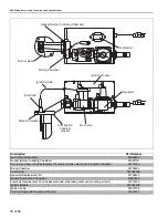
Page 84: ...0400 Transformer 90436900K Regulator Replacement Kit 02725300 Gasket Combustion Chamber 01367800 Electrode Replacement Kit includes electrode electrode gasket and mounting screws 02713200 Ignition Module 90439500K Ignition Cable 90427706 Filter Cartridge with Gasket not shown 01312401 Gasket Burner to Mixing Chamber Ignition Module Mixing Chamber Burner Head Regulator Electrode Electrode Gasket Co...

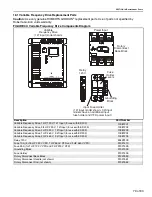
Page 85: ...ut for use with EP 203 10081204 Variable Frequency Drive 2 HP 460 V 3 Ø Input for use with EP 303 10081205 Relay 120 V 90429100 Fuse 10 A for 75 HP 230 V VFD 1 HP 460 V VFD and 2 HP 460 V VFD 91321410 Fuse 25 A for 1 HP 120 V VFD and 2 HP 230 V VFD 91321425 Grounding Block 91321300 Fuse Holder 91321400 Rotary Disconnect Base Block 91321550 Rotary Disconnect Handle not shown 91321551 Rotary Disconn...

Page 86: ...ther mostat Turn on the 24 V power switch on the relay board Press the reset button on the control board and close the doors 18 2 2 Variable Frequency Drive 25 A or 10 A Fuse To replace a fuse turn off input power to the variable frequency drive assembly at the breaker or disconnect switch Turn off 120 V power to the relay board inside the ROBERTS GORDON ULTRAVAC Controller or modulating thermosta...

Page 87: ...PIPE CONNECTION 1 2 NPT DIMENSIONS Vent Connection Size 4 10 cm or 6 15 cm Outside Air Connection Size 4 10 cm Refer to figure above for dimensional information GAS INLET PRESSURE Natural Gas 4 5 wc Minimum 14 0 wc Maximum LP Gas 10 5 wc Minimum 14 0 wc Maximum ELECTRICAL RATING 120 V 60 Hz 0 3 A Reflector Length A 20 51 cm 10 24 4 cm 6 1 2 16 cm 10 3 4 27 cm 4 10 cm 6 7 8 17 cm 3 1 2 9 cm 7 5 8 1...

Page 88: ...ia Pump Specifications Model EP 100 EP 201 EP 203 EP 301 EP 303 Horsepower Hp 1 3 3 4 3 4 2 2 Phase Ø 1 1 3 1 3 Hertz Hz 60 60 60 60 60 Voltage V 115 230 115 230 208 230 460 208 230 208 230 460 Full Load Amp Amps 4 8 2 4 6 6 3 3 2 4 2 2 1 1 12 8 11 5 5 5 5 2 2 6 R P M 3450 3450 3500 3450 3450 Motor Frame 56 56 56 90 90 Motor Enclosure TENV TENV TEFC TEFC TEFC Noise Level 5 DBA 70 70 Inlet Outlet I...

Page 89: ...RAYVAC is not installed by a contractor qualified in the installation and service of gas fired heating equipment You cannot prove original purchase date and required annual maintenance history The data plate and or serial number are removed defaced modified or altered in any way The ownership of the ROBERTS GORDON CORAYVAC is moved or transferred This warranty is nontransferable Roberts Gordon LLC...

Page 90: ......

Page 91: ......

Page 92: ......

Page 93: ......

Page 94: ......

Reviews: