background image

EN


EN -6- 

3.2 

Electrical 

3.2.1 

Lamp 

Compatible lamps 


Model 

LIF Code 

ANSI Code  

Voltage 

Power 

Flow 

Colour 

Temperature 

Lifespan 

503 

CP81 


230 V 

300 W 

7500 lm 

3200 K 

200 h 

CP82 


230 V 

500 W 

13500 lm 

3200 K 

200 h 

CP89 


230 V 

650 W 

16250 lm 

3200 K 

150 h 

T27 

GCT 

230 V 

650 W 

14500 lm 

3000 K 

400 h 

M40 


230 V 

500 W 

8500 lm 

2900 K 

2000 h 

503C 

CP81 - 120V 

FKW 

120 V 

300 W 

6900 lm 

3200 K 

50 h 

CP82 - 120V 

FRG 

120 V 

500 W 

13000 lm 

3200 K 

150 h 

CP89 - 120V 

FRK 

120 V 

650 W 

16900 lm 

3200 K 

200 h 

513 


GKV 

230 V 

600 W 

14000 lm 

3200 K 

200 h 


GLB 

230 V 

600 W 

13000 lm 

3100 K 

1500 h 

513C 


GLA 

115 V 

575 W 

13000 lm 

3050 K 

1500 h 


GLC 

115 V 

575 W 

14500 lm 

3200 K 

300 h 


523 


CDM 

230 V 

250 W 

27540 lm 

3000 K 

8000 h 

523 


CDM 

230 V 

250 W 

26000 lm 

4200 K 

8000 h 


How to place the lamp 

Warning: 


Electrically insulate prior to any intervention. Intervention must be carried out by a skilled 
technician. 


Caution : lamp and supports can be hot. The fixture must be cold prior to any intervention. 


Never touch or handle the lamp bulb with bare hands. 


1.  Unscrew the 2 screws of the lamp compartment. 
2.  Pull the lamp compartment out. 
3.  Place the lamp into the socket. 
4.  Replace the lamp compartment. You must also replace the ground wire inside the fixture. 
5.  Tighten the 2 screws of the lamp compartment. 

Summary of Contents for TIBO 503

Page 1: ...bert Juliat U S A 48 Capital Drive Wallingford CT 06492 USA phone 203 294 0481 fax 203 294 0482 info robertjuliatamerica com TIBO Projecteur de découpe Profile spot Ref Standard Standard Nord Américain North American 30 45 15 35 503 513 503C 513C 30 45 15 35 523 N A Projecteur de découpe halogène 300 650W A décharge 250W HID 300 650W Tungsten Profile Spot 250W HID PROFILE SPOT Manuel Manual ...

Page 2: ...2 3 Accessoires inclus 3 2 4 Accessoires optionnels 3 3 Installation 4 3 1 Mécanique 4 3 2 Electrique 6 3 3 Accessoires 10 4 Opération 13 4 1 Intensité lumineuse 13 4 2 Ajustement de la taille du faisceau 13 4 3 Orientation 14 4 4 Couleur 15 4 5 Contrôle de la forme du faisceau 16 4 6 Rotation de l image 17 4 7 Réglage Peak Flat version halogène uniquement 17 5 Maintenance 18 5 1 Maintenance préve...

Page 3: ...e de taille appropriée ancrée à l avant de l appareil Tenir compte de leur poids pour la charge d accrochage 11 Ne pas ouvrir l appareil sous tension 12 Attention Lampe et supports chauds Attendre que l appareil soit froid avant toute intervention 13 Ne pas modifier la sécurité 14 Resserrer régulièrement les connexions et contrôler l état des câbles Si le câble est détérioré le remplacer par un câ...

Page 4: ...illage de la lyre 6 Réglage focus 7 Accès zoom 8 Point d élingage 9 Verrouillage rotation zoom 10 Index de tilt 11 Couteaux 12 Verrouillage porte filtre 13 Porte filtre avant pour accessoire et filtre couleur 14 Réglage zoom 15 Accès zoom 16 Blocage couteaux 17 Couteaux 18 Poignée 19 Point d élingage 2 2 Etiquette d identification Description 1 Numéro de série 2 Version 01 ...

Page 5: ...éférence Description 1 PCP1716A Connecteur d alimentation IEC60309 6h 16A 2P T bleu P17 2 SGUT Porte gobo universel métal verre dépoli taille M 3 872 Crochet avec vis écrou M10 pour tube Ø48 à 51mm CMU 20Kg Certifié TÜV 4 878 Crochet acier 25x6 à vis L 23mm pour tube Ø35 à 50mm 15Kg maxi 5 CS2 Câble de sécurité longueur 600mm 6 IS500 Iris ...

Page 6: ...Positions d utilisation 3 1 2 Distance minimale entre l appareil et une matière inflammable 3 1 3 Conditions d utilisation Minimum 5 C 41 F Maximum 40 C 104 F Indice de Protection international IP20 Utilisation intérieure uniquement 1 5 m 4 9 ft ...

Page 7: ...ar une suspension auxiliaire élingue chaîne convenablement dimensionnée et ancrée à l arrière de l appareil La liaison devra être effectuée au plus court au besoin avec plusieurs tours si la longueur de l élingue ou de la chaîne le nécessite NOTA Les points d élinguage signalés peuvent etre intervertis avec leurs symétriques Attention point d accroche pour accessoires uniquement Ne pas élinguer l ...

Page 8: ...30 V 650 W 14500 lm 3000 K 400 h M40 230 V 500 W 8500 lm 2900 K 2000 h 503C CP81 120V FKW 120 V 300 W 6900 lm 3200 K 50 h CP82 120V FRG 120 V 500 W 13000 lm 3200 K 150 h CP89 120V FRK 120 V 650 W 16900 lm 3200 K 200 h 513 GKV 230 V 600 W 14000 lm 3200 K 200 h GLB 230 V 600 W 13000 lm 3100 K 1500 h 513C GLA 115 V 575 W 13000 lm 3050 K 1500 h GLC 115 V 575 W 14500 lm 3200 K 300 h 523 CDM 230 V 250 W...

Page 9: ...uds Attendre que l appareil soit froid avant toute intervention Ne pas toucher le bulbe de la lampe avec les mains nues 1 Dévisser les 2 vis de la trappe lampe 2 Retirer la trappe lampe 3 Positionner la lampe dans la douille 4 Remettre la trappe en position en s assurant que le fil de liaison terre soit bien à l intérieur du projecteur 5 Visser les 2 vis de la trappe lampe ...

Page 10: ...120 V 60 Hz Lampe 575W 4 8 A 523 230 V 50 Hz Lampe 250W CDM T Matériel de classe 1 Mise à la terre obligatoire Peut être raccordé à un gradateur électronique externe Cordon d alimentation Cordon Fiche d alimentation Câble Longueur Câblage 1 Version standard 3G1 Silicone HT 180 C 1 5 m 4 9 ft Phase marron Neutre bleu Terre jaune vert 2 Version nord américaine 3AWG18 Silicone HT 200 C style 4389 1 5...

Page 11: ...ssance 0 98 Tension de sortie maximale 350 Vac Fréquence de sortie 120 Hz Temps de réamorçage 20 min Tension d amorçage 5 kV Taux de défaillance 0 20 1000 h Protection contre les surcharges 300 Vac 48h 320 Vac Type de lampe HID 250W Puissance de la lampe 250 W Puissance d entrée 270 W Courant d entrée 1200 mA Rendement 91 8 Distance max ballast lampe 2 m Dimension L x l x h 192 x 110 x 44 8 ...

Page 12: ...FR FR 10 3 3 Accessoires 3 3 1 Porte filtre avant Etape 1 Etape 2 3 3 2 Porte gobo iris ...

Page 13: ...FR FR 11 3 3 3 Couteaux Etape 1 Etape 2 Etape 3 A Couteaux droit et gauche Logement côté lanterne B Couteaux haut et bas Logement côté zoom C Glissière gobo ...

Page 14: ...FR FR 12 3 3 4 Optique Zoom 30 45 zoom 15 35 configuration usine 30 45 Etape 1 Etape 2 Etape 3 ...

Page 15: ...e externe non fourni Version à décharge Raccorder uniquement sur prise directe non graduée 4 2 Ajustement de la taille du faisceau 4 2 1 Etendue Modèle Angle de sortie minimal Angle de sortie maximal Configuration 1 30 45 Configuration 2 15 35 cf 3 3 4 pour changement de configuration Angle de sortie DMX512 A DMX Console 0 100 ...

Page 16: ...FR FR 14 4 2 2 Contrôle 4 3 Orientation 4 3 1 Etendue Fonction Etendue PAN 0 360 TILT TU 0 55 TD 0 90 ...

Page 17: ...FR FR 15 4 3 2 Contrôle PAN TILT 4 4 Couleur Couleur fixe Type Filtre gélatine couleur ou effet standard Dimensions unités mm Installation Cf 3 2 1 ...

Page 18: ...forme du faisceau 4 5 1 Etendue Ouvert Iris 4 5 2 Contrôle Cf 3 3 Accessoires pour l installation des gobos iris et couteaux additionnels 1 couteau 2 couteaux 3 couteaux 4 couteaux Blocage couteaux Couteaux bloqués Couteaux libres ...

Page 19: ... 4 6 1 Etendue Fonction Etendue 360 Gobo Couteaux 4 6 2 Contrôle 4 7 Réglage Peak Flat version halogène uniquement 4 7 1 Etendue Fonction Peak Flat 4 7 2 Contrôle 1000 0 1000 mm 0 20 40 60 80 100 400 200 0 200 400 mm 0 20 40 60 80 100 ...

Page 20: ...èces manquantes Vérifier le serrage de toutes les pièces mécaniques vis écrous mise à la terre etc 5 1 3 Optique Le nettoyage des éléments optiques lentilles s effectue avec des nettoyants à base d alcool spécifique pour optique Accès aux lentilles du zoom 5 2 Analyse Si le problème persiste après avoir suivi la procédure de dépannage Cf 6 veuillez contacter un revendeur RJ agréé avec les informat...

Page 21: ...teur s Connexion électrique Vérifier les connexions Le faisceau n est pas uniforme Lampe dicentrée Remplacer la lampe Réglage Peak Flat Tourner la molette pour effectuer le réglage désiré Lampe non adaptée Voir la liste des lampes admissibles Faisceau de taille différente entre deux projecteurs Configurations optiques différentes Voir les chapitres sur les changements de configurations possibles 4...

Page 22: ...cation label 2 2 3 Accessories included 3 2 4 Optional accessories 3 3 Set up 4 3 1 Mechanics 4 3 2 Electrical 6 3 3 Accessories 9 4 Operation 12 4 1 Light intensity 12 4 2 Beam size adjustment 12 4 3 Orientation 13 4 4 Colour 14 4 5 Beam shaping 15 4 6 Beam rotation 16 4 7 Peak and Flat adjustment only for the tungsten version 16 5 Service 17 5 1 Preventive maintenance 17 5 2 Analysis 17 5 3 Expl...

Page 23: ...ont of the fixture 12 The combined weight of both the fixture and the accessories must be considered when choosing the load bearing capability of safety cable or bond 13 Do not open lighting fixture when the lamp is ignited 14 Warning Both lamp and lamp housing become hot during use Allow fixture to cool before servicing 15 Do not tamper with design of fixture nor any of its safety features 16 Tig...

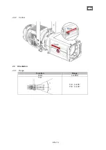
Page 24: ...ustment 7 Lens tube access 8 Safety cable attachment point 9 Lens tube rotation locking button 10 Tilt index 11 Shutters 12 Front slot locking system 13 Front slot for accessory and gel frame holder 14 Zoom adjustment 15 Zoom access 16 Shutter locking system 17 Shutters 18 Handle 19 Safety cable attachment point 2 2 Identification label Description 1 Serial number 2 Version 01 ...

Page 25: ...ies Reference Description 1 PCP1716A IEC60309 6h 16A 2P T blue P17 power connector 2 SGUT Universal M size gobo holder metal glass frosted glass 3 872 Hook clamp with M10 screw nut for Ø48 to 51mm tube CMU 20Kg TÜV certified 4 878 25x6 hook clamp for 23mm screw for Ø35 to 50mm tube 15Kg max 5 CS2 Safety cable length 600mm 6 IS500 Iris ...

Page 26: ... up 3 1 Mechanics 3 1 1 Operating positions 3 1 2 Minimum distance between a flammable material and the lighting unit 3 1 3 Instructions for use Minimum 5 C 41 F Maximum 40 C 104 F IP20 Indoor use only 1 5 m 4 9 ft ...

Page 27: ...essory such as safety bond or cable of suitable length Safety cables or bonds must be securely attached to the back of the fixture and be as short as possible or rolled up as necessary to minimise travel distance should the fixture be dislodged NOTA The indicated slinging points are symmetrical Warning hanging point for accessories only Do not use as hanging point to secure the fixture Ø 13 20 mm ...

Page 28: ... V 600 W 13000 lm 3100 K 1500 h 513C GLA 115 V 575 W 13000 lm 3050 K 1500 h GLC 115 V 575 W 14500 lm 3200 K 300 h 523 CDM 230 V 250 W 27540 lm 3000 K 8000 h 523 CDM 230 V 250 W 26000 lm 4200 K 8000 h How to place the lamp Warning Electrically insulate prior to any intervention Intervention must be carried out by a skilled technician Caution lamp and supports can be hot The fixture must be cold pri...

Page 29: ...513C 120 V 60 Hz 575W lamp 4 8 A 523 230 V 50 Hz 250 W HID lamp Class 1 equipment Mandatory earth grounding Can be connected to an external electronic dimmer Power cable Cable Connectors Cable Length Cabling 1 Standard version 503 513 HT Silicon3G1 180 C 1 5 m 4 9 ft Phase brown Neutral blue Ground yellow green 2 North American version 503C 513C 3AWG18 Silicone HT 200 C style 4389 1 5 m 4 9 ft Pha...

Page 30: ...ctor 0 98 Output voltage 350 Vac Operating frequency 120 Hz Restriction on ignition time 20 min Ignition voltage 5 kV Failure rate 0 20 1000 h Overload protection 300 Vac 48h 320 Vac Lamp type HID 250W Lamp power 250 W Input power 270 W Input current 1200 mA Efficiency 91 8 Max distance ballast lamp 2 m Dimension L x W x H 192 x 110 x 44 8 ...

Page 31: ...EN EN 9 3 3 Accessories 3 3 1 Front filter holder Step 1 Step 2 3 3 2 Gobo holder iris ...

Page 32: ...EN EN 10 3 3 3 Shutters Step 1 Step 2 A Right and left shutters slot on lamp house side B Top and bottom shutters slot on lens tube C Gobo slot ...

Page 33: ...EN EN 11 3 3 4 Optics Zoom 30 45 zoom 15 35 factory settings 30 45 Step 1 Step 2 Step 3 ...

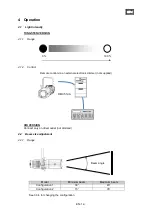
Page 34: ...trol via an external electronic dimmer not supplied HID VERSION Connect only on direct outlet not dimmed 4 2 Beam size adjustment 4 2 1 Range Model Minimum beam Maximum beam Configuration 1 30 45 Configuration 2 15 35 See 3 3 4 for changing the configuration Beam angle DMX512 A DMX Console 0 100 ...

Page 35: ...EN EN 13 4 2 2 Control 4 3 Orientation 4 3 1 Range Function Range PAN 0 360 TILT TU 0 55 TD 0 90 ...

Page 36: ...EN EN 14 4 3 2 Control PAN TILT 4 4 Colour Fixed colour Type Standard coloured gel filter Dimensions Values are in mm Installation See 3 2 1 ...

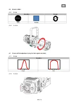
Page 37: ...15 4 5 Beam shaping 4 5 1 Range Open Iris 4 5 2 Control See 3 3 Accessories for gobo iris and additional shutters installation 1 shutter 2 shutters 3 shutters 4 shutters Locking shutter system Locked Unlocked ...

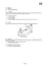
Page 38: ... 1 Range Function Range 360 Gobo shutters 4 6 2 Control 4 7 Peak and Flat adjustment only for the tungsten version 4 7 1 Range Function Peak Flat 4 7 2 Control 1000 0 1000 mm 0 20 40 60 80 100 400 200 0 200 400 mm 0 20 40 60 80 100 ...

Page 39: ...ssing parts Tighten mechanical assemblies screws bolts and nuts ground connections etc 5 1 3 Optics The cleaning of optical parts lenses shall be carried out with solutions containing alcohol Lens tube access 5 2 Analysis If there is still a problem after the troubleshooting procedures see part 6 contact RJ distributor with the following information Model version and serial number of the product D...

Page 40: ...ge the micro switch es Electrical connection Check the connections The beam is not uniform The lamp is not aligned Replace the lamp Peak Flat adjustment Turn the knob to reach the expected adjustment Non compatible lamp See the list of compatible lamps The size of the beam between two fixtures is not the same Zoom configurations are not identical See chapters referring to possible configuration ch...

Reviews: