background image

6. 操作

41

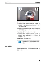
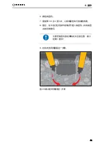
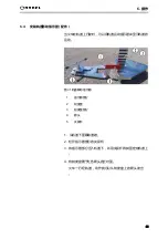
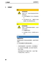
6. 撤回捣固机。

7. 重复第 1-6 步 2 到 3 次,以获得最佳和可持续的效果。

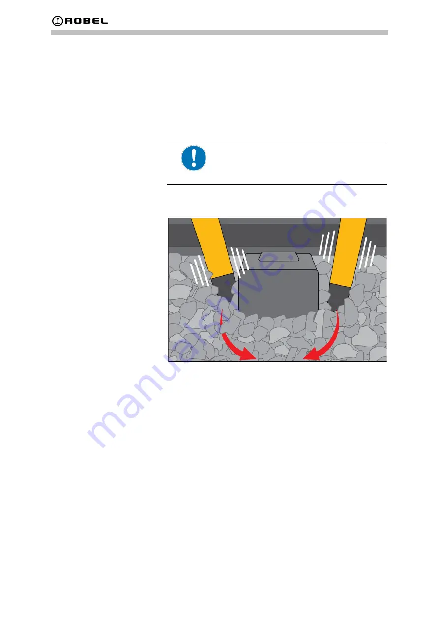
8. 最后,在不进行任何操作的情况下插入捣固机,并将捣固

点的凹痕整平。

不要把捣固机放在离轨枕太近的位置:最小
距离 1 厘米!

9. 在轨枕的两侧重复这一步骤。

图 29 在轨枕的两侧重复这一步骤

Summary of Contents for 62.05L

Page 1: ...1 Content OPERATING MANUAL ROTAMP LIGHT 62 05L Vers 02 Vertical tamper ...

Page 2: ...bel com Translation of original operating manual Status 14 07 2020 Version 5 short 2020 Robel Bahnbaumaschinen GmbH These operating instructions were issued taking into consideration the latest technology at the time of printing They are subject to change due to new developments Dimensions and weights are approximate Some photos show special designs ...

Page 3: ...s of layout 9 2 4 Design changes original parts 10 2 5 Protective devices 10 2 6 Safety regulations 10 2 7 Qualifications of staff 11 2 8 Personal protective equipment 11 2 9 Information on particular types of dangers 11 2 10 Accident prevention 14 2 11 Fire safety 16 3 Technical data 17 3 1 Drive 17 3 2 Dimensions 17 3 3 Filling Quantities 17 3 4 Weight 17 3 5 Environmental conditions 17 3 5 1 Te...

Page 4: ...5 5 1 1 Operation 25 5 1 2 Settings 25 5 2 Checking adjusting the carburetor setting 27 5 2 1 Operation at high altitude 800 m 27 5 2 2 Operation at low altitude 100 m 28 5 2 3 Adjusting idle 29 5 3 Checking the petrol engine 29 5 3 1 Engine oil level 29 5 3 2 Air filter 31 5 3 3 Filling the tank 33 6 Operation 35 6 1 Starting the engine 35 6 2 Working with the tamper 37 6 2 1 Tamping sleeper 37 6...

Page 5: ...tory setting 53 9 3 6 Changing the oil 54 9 3 7 Changing fuel pipe 55 9 4 Rubber buffers 56 9 4 1 Checking the rubber buffers 56 9 4 2 Replacing the rubber buffers 57 9 5 Centrifugal clutch 58 9 6 Tamping tool 59 9 6 1 Checking the tamping tool for wear 59 9 6 2 Replacing the tamping tool 60 9 6 3 Changing bearings 68 9 7 Signs and labels 71 10 Environmental protection and disposal 72 10 1 Environ...

Page 6: ... for any legal consequences In the event of differences between prevailing regulations that apply to use of the product and the manufacturer s or sub contractor s specifications whichever limitations are the most stringent must apply The buyer must provide all necessary machinery equipment and material resources for putting the delivered product into operation and training staff He must also make ...

Page 7: ...tions supplied by the manufacturer or supplier 1 4 Liability Exclusions The manufacturer declares himself to be exempt from any responsibility for damage arising when the product is not used in a designated way This also includes use of the machine without safety mechanisms Any use of the product other than that specified above is not designated and endangers the lives and health of operating and ...

Page 8: ...must equip the goods delivered with all fittings nec essary to meet relevant operational and safety regulations norms statutory regulations or other regulations e g fire ex tinguisher first aid box signal and telecommunications equipment additional warning devices protective clothing safety notices etc Unless otherwise agreed no fittings of this nature are provided with the goods delivered Further...

Page 9: ...rating company DANGER Indicates that non compliance with the in structions will result in death or severe irre versible injuries of the operating personnel WARNING Indicates that non compliance with the in structions may result in death or severe irre versible injuries of the operating personnel CAUTION Indicates that non compliance with the in structions may result in minor reversible inju ries o...

Page 10: ...to actually fit the designated pro tective devices during operation or to leave them in the predetermined factory position The person commissioned to carry out maintenance must refit the protective devices after completing his work 2 6 Safety regulations The necessary requirements for protecting life health material property and the environment when handling the product must take precedence Before...

Page 11: ...se of responsibility reliability Necessary national requirements qualifications minimum age No influence of alcohol medicines drugs or fatigue etc 2 8 Personal protective equipment The approved personal protective equipment has to be used when operating and maintaining the product Wear protective gloves Wear ear protection Wear steel capped work shoes The protective equipment is determined by Thes...

Page 12: ... jerky move ments Avoid adverse movements and poor posture When the engine is running there is a risk of injury from rotat ing and hot components Only authorised technical personnel may work on the com bustion engine Switch off the engine and allow it to cool down Check the engine regularly and rectify any faults found straight away e g damage leaks Listen out for unusual noises or vibrations etc ...

Page 13: ...ated may cause the fuel to expand and emerge through openings in the filler cap Do not overfill the tank so that fuel rises up into the filler neck Some parts may be live and may cause severe to fatal injuries when getting in contact with them Work on the electrical system only by authorised electrical engineers Rectify faults contact faults external damage to cables or housings etc straight away ...

Page 14: ...posal Dispose of components according to material groups steel plastics oils etc Collect waste oil in line with the relevant regulations and dispose of it accordingly Unauthorised start up and misuse can result in dangers and damage of any kind Unauthorised start up by unauthorised persons is strictly prohibited It is up to the operating company to assess this risk It is the responsibility of the ...

Page 15: ...moved immediately to prevent a fire hazard or risk of slipping Keep suitable oil binding agents and cleaning agents at hand Before leaving the product perform the following checks It has been shut down properly It is secured against moving unintentionally Tools and accessories are stowed away safely Use only machines appliances and tools that work proper ly Rectify smaller faults straight away in ...

Page 16: ...ny actions that may cause a fire or favour the spreading of a fire In addition all measures required to prevent the development or spreading of a fire must be taken in individual cases In general any fires that occur are to be fought only with powder extinguishers The following fire safety measures must be adhered to Use only approved fire extinguishers powder type extin guishers of the prescribed...

Page 17: ...3 EPA Phase 2 EU level 2 3 2 Dimensions Length 1 080 mm Width 510 mm Height 410 mm 3 3 Filling Quantities Fuel 0 6 l Motor Engine oil SAE 10W 30 0 06 l Tamping pick Engine oil SAE 10W 30 0 06 l 3 4 Weight Tamper 19 6 kg 3 5 Environmental conditions 3 5 1 Temperature Temperature range operation 20 C to 50 C Temperature range transport 20 C to 60 C Temperature range storage 20 C bis 60 C 3 5 2 Opera...

Page 18: ... worker e g staying at different places machines 3 6 1 Noise emissions Sound pressure level LpA 113 6 dB A Sound power level LWA 109 0 dB A 3 7 Vibration Total vibration vector sum of three directions 7 7 m s2 3 8 Digital tach hour meter Value Range Revolutions per minute RPM 0 60 000 U min UPM Max value of revolutions per minute ever reached RPM 0 60 000 U min UPM Operating hours 0 99 999 hours V...

Page 19: ...nbalance to produce the vibrations Mounted on the engine is the engine stop button for cutting it off 4 1 2 Tamping pick The tamping pick consists of two parts The tamping tool is located on its bottom side 4 1 3 Guiding frame The guiding frame is fixed to the vibrator with damping via eight rubber metal buffers The throttle handle is fitted on the right hand side ...

Page 20: ...Petrol engine 2 Protective cover 3 Guiding frame 4 Throttle handle 5 Rubber buffer 6 Tamping tool 7 Tamping pick 4 3 Work station The operator stands behind the machine and grabs the han dles with both hands For information on working ergonomical ly see chapter 6 2 1 ...

Page 21: ...ne Fig 2 Petrol engine 1 Handle of recoil starter 2 Fuel tank 3 Engine stop button 4 Centrifugal clutch 5 Throttle lever 4 5 Signs and labels 4 5 1 Signs and labels used Fig 3 Sign Starting by instructed personnel only Fig 4 Type label Ex ample ...

Page 22: ...ig 5 Transport Storage position Fig 6 Observe operat ing instructions Fig 7 Logo of manufacturer Fig 8 Tank capacity Fig 9 STOP next to Engine Stop Regularly check that all signs are present and intact Replaces labels if necessary ...

Page 23: ...product Fig 10 Position on the product 1 Label Starting by instructed personnel only 2 Label Tank capacity 3 Label Observe operating instructions 4 Logo of manufacturer 5 Type label 6 Label STOP 7 Logo of manufacturer 8 Label Transport Storage Position ...

Page 24: ...ductive Tach hour meter is capable of displaying three values Operating hours engine off Actual RPM engine running Max RPM ever reached Fig 11 Example display of actual rpm 1 Button 4 7 Accessories Rail movement indicator EDP No 886 823 0001 Fig 12 Rail movement indicator ...

Page 25: ...hows 2 RPM and the max RPM stored Fig 14 Max RPM stored If no button is pushed for around 8 seconds the display automatically switches back to standard mode 5 1 2 Settings The digital Tach hour meter has been factory set according to the engine used Do not change settings without reason The digital Tach hour meter can be used both for two stroke and four stroke engines 1 Press the button once The ...

Page 26: ...ds The display flashes 3 Press the button once The display is showing the other setting By pushing the button again the display toggles between the two settings 4 Set 1P1r for two stroke engines or 2P1r for four stroke engines 5 Once the display is showing the correct setting wait for around 10 seconds The displayed setting has been stored and the display automatically returns to standard mode Cha...

Page 27: ...e air This results in low engine performance and high consumption Tools Screwdriver 1 Start the engine and allow to warm up 2 Hold the tamper so that the tamping tool does not touch the ground 3 Apply full throttle and evaluate he sound of the engine If the engine is not running smoothly this is an indication that the mixture is too rich 4 Turn the screw H 2 clockwise in steps of 1 8 turn each ste...

Page 28: ... lower altitude 5 2 2 Operation at low altitude 100 m In low altitude MSL the mixture of fuel air becomes too poor This causes reduced engine performance and overheating which may result in engine damage Tools Screwdriver 1 Start the engine and allow to warm up 2 Hold the tamper so that the tamping tool does not touch the ground 3 Apply full throttle and evaluate he sound of the engine If the engi...

Page 29: ...n prior to engine operation at high alti tude 5 2 3 Adjusting idle After the mixture has been set according to the altitude it might be necessary to re adjust the idle setting see ch 9 3 4 5 3 Checking the petrol engine 5 3 1 Engine oil level NOTICE Risk of engine damage There is a risk that engine lubrication will not work if the oil level falls too low The engine will be seriously damaged Make s...

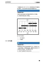
Page 30: ... requirements for API service category SF or higher or equivalent quality Always check the API service label on the oil container to ensure that it contains the letters SF or those of a higher category or equivalent quality SAE 10W 30 is recommended for general use Oils with the other viscosities indicated in the table can be used if the aver age temperature at the place of use lies within the ran...

Page 31: ...NOTICE Risk of damaging the air filter If compressed air is used to clean the air filter the sensitive filter elements may be destroyed Brushing forces the dirt into the fibers Do not use compressed air to clean or dry the air filter Do not brush the dirt away ROBEL recommends replacing air filters and spark plugs at regular intervals in line with the specifications in the maintenance schedule Onl...

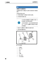
Page 32: ...5 Preparing the machine 32 Fig 21 Air filter 1 Fixing bolt 2 Filter element paper 3 Loop 4 Plate 5 Separator plate 6 Filter element sponge 7 Air filter cover ...

Page 33: ...t use any oil petrol mixes or petrol that is not clean Avoid dirt dust or water from getting into the fuel tank Use clean fresh and unleaded petrol with an ethanol vol ume percentage of no more than 10 Risk of damage to paintwork Fuel can have an aggressive effect on paint and some plas tics Make sure not to spill any fuel when refuelling 1 Keep the handle dry clean and free of fuel and oil 2 Lay ...

Page 34: ...5 Preparing the machine 34 Fig 22 Filling the tank 1 Fuel tank cap 2 Fuel upper limit 3 Fuel tank ...

Page 35: ...lide to CLOSE position Full opening if the engine is a bit warm Easy use of the throttle handle allows a better start Fig 23 Close the choke lever 1 Choke Position CLOSE 2 Continue to push the primer pump until fuel comes into the primer pump In general 7 to 10 pushes Fig 24 Primer pump 1 Primer pump ...

Page 36: ...lt then pull out the handle forcefully 4 Once engine starts set choke lever to the OPEN position Open the choke lever gradually while checking the engine operation Be sure to open the choke lever to the full in the end In cold or when the engine is cooled down never open the choke lever suddenly Other wise the engine may stop Fig 25 Move choke lever to OPEN 1 Choke Position OPEN 5 Warm up the engi...

Page 37: ... the weight of the up per part of your body to apply the vertical force this will relieve the backbone 1 Hold the tamper upright and place it next to the sleeper 2 Press down the throttle handle by hand The tamping tool starts to vibrate 3 Continue holding the tamper by the handles and apply force by using the weight of the upper part of the body 4 Dive vertically into the ballast until the tip of...

Page 38: ...ig 27 Distances between taming tool and sleeper 5 Pull the tamper towards the operator so that the ballast is compacted under the sleeper Fig 28 Compact ballast under the sleeper Distance 1 to 5 cm Distance 5 to 10 cm ...

Page 39: ...e tamping tool too close to the sleeper distance min 1 cm 9 Repeat this procedure on both sides of the sleeper Fig 29 Repeat this procedure on both sides of the sleeper 6 2 2 Tamping track panel For optimum tamping result all sleepers must be tamped from both sides directions FORWARD and BACKWARD Example illustration green forward tamping from right to left red backward tamping from left to right ...

Page 40: ...prox 1 minute press the STOP button Engine stops 6 4 Installing rail movement indicator accessories The rail movement indicator can be used to show the rail movement when a train is travelling over the track Fig 31 Rail movement indicator 1 Indicator part 2 Scale 3 Scale part 4 Arrow 5 Clamping lever 1 Remove the ballast from under the rail 2 Loosen the clamping lever on the indicator part 3 Push ...

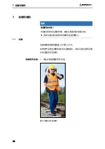
Page 41: ... vertical tamper with its motor to the top 7 1 Transport The temperature range for transporting the machine is 20 C to 60 C If the product is placed in its original packaging and properly lashed down it can be transported by any means of transport without damage 1 Carry the vertical tamper to the workstation Fig 32 Carrying the vertical tamper Transport to the workstation ...

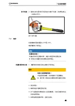
Page 42: ... extremely flammable and is explosive under certain conditions Obey the safety notes concerning the combustion engine and fuel in Chap 2 2 Drain off the fuel 3 Make sure that the oil filling cap is tightened securely 4 Unscrew the fuel tank cap and drain the fuel into a suitable container To do this tilt the engine towards fuel filler neck 5 If there is any foreign matter remaining in the fuel tan...

Page 43: ...tighten the fuel tank cap 10 Then continue to operate the engine until it stops 11 Remove the spark plug and drip several drops of engine oil through the spark plug hole 12 Gently pull the starter handle so that engine oil will spread over the engine and attach the spark plug ...

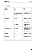
Page 44: ...ea level see chapter 5 2 Clogged Fuel filter Clean fuel filter see chap ter 9 3 2 Oil level too low Check oil level see chap ter 5 3 1 Engine runs not smoothly low performance Carburetor setting too rich Adjust carburetor setting according to actual altitude above sea level see chap ter 5 2 Clogged Fuel filter Clean air filter see chap ter 9 3 1 Worn tamping tool Wear Change tamping tool see chapt...

Page 45: ...ine damage There is a risk of engine damage if the spare parts used do not meet the specified quality requirements Use only original spare parts or parts of equivalent speci fication 1 Use only the recommended lubricants and when carrying out repairs use only original spare parts This is important firstly for warranty cases and second ly to enhance the operational reliability of the product Correc...

Page 46: ...0 operating hours Vibration tamper Clean Vibrator Check operational safety Rubber buffer1 Visual check Replace if necessary formation of cracks see ch 9 4 Tamping tool Check for wear replace when necessary See ch 9 6 1 replace ment see ch 0 After 10 hours follow ing initial commission ing and tamping tool replacement check the measurement of 224 mm between the tamping tool and the tamping pick fla...

Page 47: ...ficantly NOTICE Risk of damage Cleaning the product with solvents aggressive or combustible cleaning agents may result in damage The use of high pressure washers can result in damage caused by water getting into the motor silencer air filter carburettor and articulated joints of the product Do not use any solvents or aggressive combustible clean ing fluids Do not use petrol for cleaning Do not use...

Page 48: ...d explosion If the air filter is cleaned with petrol or a low flash point solvent a fire or an explosion could occur Do not use petrol or low flash point sol vents for cleaning the air filter insert NOTICE Risk of increased engine wear If the engine is operated without an air filter particles of dust can enter the combustion chamber Scoring of the en gine moving parts occurs pistons and cylinders ...

Page 49: ...te 4 3 Loosen fixing bolt 1 4 Pull and remove the air cleaner cover 7 5 Remove the filter elements 2 6 and tap them to remove dirt 6 Remove the filter element sponge immense it in warm water or in water diluted neutral detergent 7 Dry it completely 8 Do not squeeze or rub it when washing 9 Clean the filter element paper by tapping it gently Do not wash the filter element paper 10 Refit the cleanin...

Page 50: ...uel filter from the fuel filler neck using a wire Fig 35 Cleaning the fuel filter 1 Fuel pipe 2 Hose clamp 3 Fuel filter 4 Check the fuel filter for any contamination If it is contami nated wash it using a non flammable solvent or one with a high flash point Replace the filter if it is contaminated ex cessively 5 After checking cleaning or replacing fix the fuel filter onto the fuel pipe with the ...

Page 51: ...CMR6A NGK Spare part spark plug EDP No 900 044 0408 The recommended spark plug has the correct heat rating for normal engine operating temperatures 1 Remove the spark plug connector 2 Clean the surrounding area of the spark plug 3 Unscrew the spark plug with a suitable spark plug wrench 4 Visually inspect the spark plug Discard the spark plug if there is apparent wear or if the insulator is cracke...

Page 52: ...7 Ensure that the sealing washer is satisfactory then screw the spark plug back in by hand to avoid cross threading When installing a new spark plug tighten turn after it seats to compress the sealing washer When reinstalling the original spark plug tighten 1 8 to 1 4 turn after the spark plug seats to compress the sealing washer 8 After the spark plug is seated tighten it with a spark plug wrench...

Page 53: ...to factory setting If multiple changes have been carried out on the carburetor without success it might be beneficial to reset the carburetor to the original setting and start adjustment again from this point Tool Screwdriver Fig 39 Screws L 1 and H 2 1 Tighten the screw H 2 fully CW then turn it 2 turns in the opposite direction CCL 2 Tighten the screw L 1 fully CW then turn it 2 turns in the opp...

Page 54: ... in with the rubbish or pour it on the ground or into drains We suggest you take the oil in a sealed con tainer to your local waste oil Drain the oil while the engine is still warm to ensure speedy and complete draining 1 Make sure that the tank cap is tightened securely 2 Place a large container pan etc Fig 40 Changing the oil 3 Remove oil cap tilt the tamper toward the filler hole and drain out ...

Page 55: ...l leaks can cause a fire If any leakage is detected during inspec tion replace the fuel pipe immediately Observe the safety information on com bustion engine and fuel in chapter 2 Fig 41 Fuel pipe 1 Fuel pipe 1 Replace the fuel pipe every year or every 200 operating hours 2 If any leakage is detected during inspection replace the fuel pipe immediately ...

Page 56: ...en the handle mounting plate and tamping tool are wear parts 1 Replace the rubber buffers when necessary visible cracks porosity Fig 42 Rubber buffers 1 4x between handle and mounting plate EDP No 988 015 0446 2 4x between mounting plate and tamping tool EDP No 900 162 0104 Do not reuse used hexagon nuts EDP No 990 985 1000 ...

Page 57: ...ers A significant de crease of service life of the rubber buffers is the result If rubber buffers are gripped with pliers without additional protection they will be damaged Rubber buffers must not be screwed in twisted or misa ligned Use additional protection if you grip rubber buffers with pliers in order to protect them Fig 43 Left twisted seam right vertical seam 1 Hold rubber buffer tight usin...

Page 58: ...e 58 9 5 Centrifugal clutch Every 100 operating hours 1 Unscrew the check screw 1 and refill approximately 2 cm3 of ball bearing grease Fig 45 Maintaining centrifugal clutch 1 Check screw 2 Screw in the check screw ...

Page 59: ...n away NOTICE Risk of damage to tamping pick the tamping tool is worn and the aluminium of the tamping pick is visible there is danger of holes forming As soon as aluminium is visible you have to replace the tamping tool Fig 46 Measuring the length of the tamping tool 1 Measure the length of the tamping tool using a tape measure New tamping tool Length 40 5 cm Worn tamping tool Length 36 cm 2 As s...

Page 60: ...nd nuts have been damaged too In this case it is impossible to remove the fas tening crews with the aid of standard tools Fig 47 Cut screws 1 Use an angle grinder and cut the two screws see arrows one screw on each side Fig 48 Tamping tool removal device optional 1 Tamping tool removal device 2 Tamping tool support 3 Hexagonal receiver Order No Tamping tool removal device EPD No 8998950200 Removin...

Page 61: ... the tamping tool removal device in the counterclockwise direction 4 Remove the tamping tool from the tamping pick 1 Measure the length for the tamping pick and mark it at 34 5 cm Fig 49 Mark tamping pick Safety equipment Protective gloves Safety goggles Respiratory Mask Fig 50 Safety equipment Sliding new tamping tool Injection of resin for longer service life ...

Page 62: ...cope of delivery 1 Injection epoxy resin 2 Adapter 3 Mixing tube 4 Mask 5 Protective gloves 6 Auxiliary plate Note data sheets and safety data sheets Tools means material Multi purpose grease Brush Paper towel File Side cutter ...

Page 63: ... of aluminium tube and to the centering Grease is used as a release agent so that the alumini um tube has no connection with the tamping tool Fig 52 Apply grease to the aluminium tube and to the centring 3 Wipe off excess multipurpose grease Fig 53 Wipe off excess grease ...

Page 64: ...intenance 64 4 Prepare injection Fig 54 Remove protective cap Fig 55 Attach adapter unscrew mixing tube shorten mixing tube 5 Place auxiliary plate on tamping tool and insert injection into auxiliary plate ...

Page 65: ...65 9 Maintenance Fig 56 Place auxiliary plate on tamping tool Fig 57 Insert injection into auxiliary plate ...

Page 66: ...g tool When filling make sure that the epoxy resin is just on the bottom of the tamping tool 7 Remove injection and auxiliary plate 8 Within 2 minutes push the tamping tool onto the alumini um tube and check control dimension 224 mm see chap Fig 59 push the tamping tool onto the aluminium tube ...

Page 67: ...ws uniformly on both sides each screw with 20 Nm Fig 60 Tighten the fixing screws to 20 Nm 11 Check the distance between the tamping tool and the tamping pick flange see illustration below Target measurement 224 mm Fig 61 Checking the reference measurement 12 Store vertically for about 5 hours and allow the resin to harden ...

Page 68: ...F6 60 ml engine oil SAE 10W 30 NOTICE Risk of damaging the tamping pick If the flange oft he tamping pick or the rim is hit directly with any tool it is very likely that the tamping pick will suffer dis tortions and will be irreversibly damaged It will become im possible to dismount the eccentric shaft Use tapping device 1 optional for disassembly of eccen tric shaft NOTICE Risk of contamination d...

Page 69: ...ngine shaft Fig 64 Knocking device Order Number for knocking device EDP No 899 895 0001 2 Dismount the whole assembly the tamping pick off the vertical tamper Untighten the screws M10 11 of flange 10 with open end spanner AF17 and the two screws M8 12 that attach the coupling element to the engine shaft under rubber bellow with Allen key AF6 3 Detach tamping pick together with eccentric shaft 9 fr...

Page 70: ... dur ing assembly If force is applied although this stop has been reached the bearings may be damaged Consider the dimension 74 mm during assembly Do not apply any more force once this dimension has been reached The lower bearing floating bearing needs oil in order to reach a long working life Make sure to fill in the appropriate amount of engine oil 60 ml 10 Place tamping pick with the flange poi...

Page 71: ... and intermediate shaft is cor rect Align if necessary 15 Join tamping pick and engine 16 Insert screws into flange and tighten 17 Degrease the two screws that attach the coupling element of the intermediate shaft to the engine shaft under rubber bellow and apply high strength screw retention 18 Insert the two screws 1 for the engine shaft and tighten with 20 Nm 9 7 Signs and labels Regularly chec...

Page 72: ...ute the ground or get into the drains 10 2 Disposal The disposal of the product including machine parts engine oil and fuel will depend upon the local regulations for waste disposal If the product reaches the end of its life cycle ensure a safe and proper disposal particularly of parts or substances which are harmful for the environment These include among oth ers fuel lubricants and plastics 1 Si...

Page 73: ...73 11 Appendix 11 Appendix Fig 66 EC Declaration of Conformity EC Declaration of Conformity ...

Page 74: ...Content 目录 1 产品说明书 ROTAMP LIGHT 62 05 L 版本 02 立式捣固机 ...

Page 75: ...riestraße 31 83395 弗赖拉辛 电话 49 086 54 609 0 传真 49 086 54 609 445 电子邮箱 info robel com 网址 www robel com 产品说明书译文版 日期 2020 年 7 月 14 日 第 5 简版 德国 Robel 轨道机械有限公司 2020 版权所有 本产品说明书是在考虑 印刷时的最新技术的基础上编制的 并且会随着技术发展进行更改 尺寸和重量都为近似值 有些照片显示的为特殊设计 ...

Page 76: ...2 安全 10 2 1 指定用途 10 2 2 可预见的误用 10 2 3 布局惯例 10 2 4 设计变更 原装零件 11 2 5 防护装置 11 2 6 安全规程 11 2 7 工作人员资质 12 2 8 人身防护设备 12 2 9 关于特定类型危险的信息 13 2 10 事故预防 16 2 11 消防安全 17 3 技术参数 18 3 1 驱动装置 18 3 2 尺寸 18 3 3 加油量 18 3 4 重量 18 3 5 环境条件 19 3 5 1 温度 19 3 5 2 运行高度 19 3 6 噪声排放及振动 19 3 6 1 噪声排放 19 3 6 2 振动 19 3 7 数字式转速 小时 20 ...

Page 77: ...4 6 数字式转速 小时 26 4 7 配件 26 5 机器准备 27 5 1 数字感应式转速 小时 27 5 1 1 操作 27 5 1 2 设置 27 5 2 检查 调整化油器设置 29 5 2 1 高空作业 800 米 29 5 2 2 低空作业 100 米 30 5 2 3 怠速调整 31 5 3 检查汽油发动机 32 5 3 1 发动机油位 32 5 3 2 空气过滤器 33 5 3 3 加油 35 6 操作 37 6 1 启动发动机 37 6 2 与捣固机一起工作 39 6 2 1 捣固 轨枕 39 6 2 2 捣固 轨排 42 6 3 关停发动机 42 6 4 安装轨道移动指示器 配件 43 7 运输与储存 44 7 1 运输 44 7 2 储存 45 8 故障措施 47 ...

Page 78: ... 2 清洗燃油过滤器 54 9 3 3 火花塞维护 55 9 3 4 怠速调整 57 9 3 5 将化油器复位到出厂设置 57 9 3 6 换油 58 9 3 7 更换燃油管 59 9 4 橡胶缓冲器 61 9 4 1 检查橡胶缓冲器 61 9 4 2 更换橡胶缓冲器 62 9 5 离心式离合器 63 9 6 捣固机具 64 9 6 1 检查捣固机具的磨损情况 64 9 6 2 更换捣固机具 65 9 6 3 更换轴承 73 9 7 标志和标签 76 10 环境保护与处置 77 10 1 环境保护 77 10 2 处置 77 11 附录 78 ...

Page 79: ...目录 6 ...

Page 80: ...列表 可以更改顺序 度量 度量 度量 顺序不得更改 1 2 总则 一般情况下 使用本产品必须遵守适用法律要求和事故预防措 施 如未遵守 设备操作人员承担任何法律后果的责任 如果适用于产品使用的现行法规与制造商或分包商的规范之间 存在差异 则以最严格的限制规定为准 买方必须提供一切必要的机械 设备和材料资源 以便将交付 的产品投入生产并培训员工 买方还必须提供无限制 安全和 足够长的轨道和作业区段 在这些区段上 员工可以学习如何 操作和使用交付的产品并进行实操训练 产品制造商或供应商 对买方的特定人员配置和操作环境没有影响 因此 对本手册 的有效性不承担任何责任 但是 罗湃尔轨道机械有限公司及其客户服务部门乐于提供进 一步的建议 培训或其他咨询服务 更多细节和条件可另行 获取 ...

Page 81: ...严格遵循产品使用和安全方面的官方规定 特别是涉及工 作场所和环境的安全与保护以及制造商或供应商提供的操作 维护和安全规定或其他指示 才可以替换 维护和操作本产品 1 4 责任免除 制造商声明 对于产品未按指定方式使用引起的任何损坏 包括在没有安全措施的情况下使用机器 制造商不承担任何责 任 本说明书并未指定除产品规定使用方式以外的 危及操作和维 护人员的生命健康以及操作方的物质财产的任何使用 如果 下列情况发生 该产品的制造商声明 对属于操作方或第三方 的人员或财产的损害不承担任何责任 该产品没有按照规定的方式使用 操作和维护人员没有阅读和理解上述说明 并将该产品用 于其他用途 操作或维护人员不具备足够的资格 该产品已在超过限值的条件下使用 该产品没有在规定的时间内进行保养 使用非原装备件对产品进行了保养 未经许可 对产品部件或附件进行了更改 这些对人身或物质财产损害的责任免除并不影响其他...

Page 82: ...验收 设备及经营许可证 买方有责任检查所交付货物的条件 配件 性能 特别是安全 性能是否与所商定的有关规格以及合同中的规定相符 买方必须为交付的货物配备一切必要的配件 以符合有关的操 作和安全规程 规范 法规或其他规定 如灭火器 急救箱 信号和通讯设备 附加报警装置 防护服 安全告示等 除非另有约定 货物交付时不提供此等性质的配件 此外 买方有责任证明所交付的货物已通过认证 供有关当局 使用 制造商或供应商为此目的需提供的任何文件 说明 证明 认证等 应在供应合同中加以规定 为取得操作认证所需的任何额外措施和费用都必须由买方承担 1 7 本说明书的有效性 本说明书适用于以下 EDP 编号的产品 EDP 编号 899 990 0005 EDP 编号 980 620 5190 ...

Page 83: ...预见的误用 立式捣固机不得用于拆除或类似工程作业 2 3 布局惯例 本说明书利用下列警告文字及符号来保障操作人员的安全以及 保护其不会受到伤害 并防止对运营公司的物质资产造成损害 危险 该符号表明不遵守产品说明书将导致操作人 员死亡或严重 不可逆的 伤害 警告 该符号表示不遵守产品说明书可能导致操作 人员死亡或严重 不可逆的 伤害 小心 该符号表示不遵守产品说明书可能导致操作 人员轻微 可逆的 伤害 通知 该通知指出不遵守操作说明可能对运营公司的产品或其他资 产造成损害 该符号表示其包含关于产品及其操作或关于 现有部分说明的重要信息 ...

Page 84: ...为产品设计的 使用未经批准的备件可 能导致产品的结构特性发生变化或受损 对于因使用此类零件或劣质操作液体而造成的任何损坏 制造 商不负任何责任 2 5 防护装置 操作安全装置会对操作人员和他人的生命构成危险 操作者有义务在操作过程中切实安装好指定防护装置 或 保持其预定出厂状态 受委托进行维护的人员在完成工作后 必须重新安装防护 装置 2 6 安全规程 操作本产品时 必须优先考虑保护生命 健康 物质财产和环 境的必要要求 在使用本产品前 请确保你能证明所有受影响的人员均已 知悉下列有关规例及条文 国家安全法规 各建筑守则及工程规则的条文 各专业及行业协会的规定 职业与环境健康和安全条例 审批规程 公司内部规章制度 ...

Page 85: ...工作人员资质 运营公司对操作人员就分配给他的作业任务进行了培训 并告 知操作人员不适当的行为可能带来的危险 产品综合培训 了解操作和维护说明的内容 了解供应商及辅助设备的操作和维护说明的内容 了解有关产品和辅助设备的国家法律和法规 身心健康 具有专注力 责任感 可靠性 必要的国家要求 资格 最低年龄 无酒精 药物 毒品 疲劳等影响 2 8 人身防护设备 在使用和维护产品时 必须使用经批准的人身防护设备 戴上防护手套 戴上听力保护装置 穿钢头工作鞋 防护设备根据下列项确定 本产品说明书 国家安全规则 专业行业协会规则 等 如果运营公司现行有效的规定与制造商及其供应商的规定 有差异 则最严格者适用 操作人员 对操作人员的要求 ...

Page 86: ...会指 南 本产品说明书的警告通知述及的价值观与德国法规有关 进行风险评估 并考虑到关于操作人员和运输作业的下列 方面 运输频率 年龄 性别 操作人员健康状况 遵守起重及运输重型机械或设备的有关指南 在某些活动中 如果不通过控制装置采取必要的谨慎预防措施 则有可能损伤肌肉 肌腱 关节或骨骼 比如通过换向启动 器来启动发动机 用力拉换向启动器 但要避免急动 避免不利的动作和不良的姿势 当发动机运转时 旋转部件和热部件有造成人身伤害的风险 只有经过授权的技术人员才能在内燃机上工作 关掉发动机 让它冷却 定期检查发动机并立即纠正发现的任何故障 如 损坏 泄 漏等 留意不寻常的噪音或振动等 进行维护时必须关闭发动机 小心过热的部件 重物危险 不符合人体工程学操作的危 险 内燃机危险 ...

Page 87: ...有一氧化碳 这是一种无色 无味 有毒的气体 如果吸入一氧化碳 可能导致严重的脑 损伤 甚至死亡 只能在室外操作内燃机 只有在安装排气排烟装置的情况 下 才可在密闭的空间内操作 不要吸入废气 燃料是高度易燃的 在一定条件下与空气混合会发生爆炸 如果燃料处理不当 会有造成人身伤害或损坏物质财产的危险 关掉发动机 让它冷却后再加油 在通风良好的区域以及发动机停机后加油 操作燃料时不要吸烟 保持燃料远离明火和火花 避免反复或长时间接触皮肤或吸入蒸气 加油时小心不要弄洒燃油 只使用合适的加油装置来补充燃料 例如 漏斗 立即擦掉溢出物 如果油箱过满 随后产生的热量可能导致燃料膨胀 并通过加 油口盖上的开口溢出 不要把油箱加得过满 这样燃料会升到加油口颈 燃料危险 ...

Page 88: ...任何带电的线路 检查接地电缆是否安装到位且牢固 检查接地电缆的连接面是否洁净且无腐蚀 如果操作人员不经常佩戴个人听力保护器 会对身体尤其是听 力造成永久性损害 戴上听力保护装置 接触热部件有受伤的危险 请勿触摸受热部件 在对受热部件进行操作之前 关闭发动机 让热部件冷却 至少 30 分钟 火灾风险 将机器放置在离建筑物和其他设备至少一米远的地方 确保发动机附近没有易燃材料 并且当发动机运转时其上 没有放置任何物体 机器适当冷却之前 不得盖住或加载机器 振动传递到人体会对健康造成不利影响 虽然操作导向手柄通 过橡胶缓冲器进行减振 但无法实现完全消除振动 戴上带衬垫的手套 工作过程中 将无振动活动与对肌肉的主要动态需求相结 合 电气电压危险 噪音危险 热危险 振动危险 ...

Page 89: ... 2 10 事故预防 土木工程师协会的 事故预防规例 也适用于本说明书 并须 仔细阅读和遵守 始终遵守通用的和内部的预防事故的规定 考虑与产品的特殊作业相关的潜在事故风险 并提供适当 的培训 在产品投入使用前 应检查产品是否处于正常工作状态 设备 装置 工具 附件 安全设备等都齐套且完好无损 检验和维护工作已按时以专业方式进行 工作液已加满 燃料 润滑剂等 满足你及其他人 物质财产和环境方面安全作业的所有先 决条件 注意产品和工作区域的特殊危险 特别是 人与障碍 符合安全间隙 邻近轨道上的交通 确保所有保护设备安装牢固 遵守所有操作上必要的安全措施 操作液体 油 润滑脂等 泄漏必须立即去除 以防止发 生火灾或滑倒的危险 手边应备有适当的油粘合剂和清洗 剂 环境损害风险 擅自启动导致的危险 ...

Page 90: ...救措施和相应 设备 立即补充已用完的材料 储存急救设备 急救箱 毯子等 和容易取到的灭火器 携带保护事故现场的材料 2 11 消防安全 当燃料 油 油漆或清漆着火时 就会释放出有毒的烟雾 此外 必须根据具体情况采取一切必要的措施 防止火灾的发 生或蔓延 电气设备闷燃时 烧焦的电缆释放出有毒的烟雾 燃料 油或 油漆起火时也会释放有毒烟气 每个人都有义务尽可能合理地避免进行任何可能引起火灾 或有利于火灾蔓延的操作 此外 必须根据具体情况采取 一切必要的措施 防止火灾的发生或蔓延 一般来说 任何发生的火灾都只能用干粉灭火器来扑灭 必须遵守下列消防安全措施 只使用经批准的防火级别的灭火器 粉末型灭火器 定期检查灭火器 并确保其配有检验标签 至少每 2 年一 次 检查失效日期 使用灭火器后 立即更换 急救 一般要求 ...

Page 91: ...0 RPM 7 500 U min 下的输出 1 5 kW 燃料 汽油 至少 91 ROZ 相当于 86 辛烷值 无铅汽油 E10 或以下 烷基化汽油 四冲程 每运行小时耗用量 大约 0 9 L h 废气排放 根据加州空气资源委员 会三级 美国环境保护 署二阶段 欧盟二级 3 2 尺寸 长度 1080 毫米 宽度 510 毫米 高度 410 毫米 3 3 加油量 燃料 0 6 升 电机 发动机油 SAE10W 30 0 06 升 捣固镐 发动机油 SAE10W 30 0 06 升 3 4 重量 捣固机 19 6 公斤 ...

Page 92: ...0 至 60 3 5 2 运行高度 标准阀门设备和化油器出厂设置下 100 米至 800 米 理想状态为 400 米 调整运行高度参见第 5 2 章 3 6 噪声排放及振动 由于作业时的噪音超过了适用于人的噪音标准 因此必须佩戴 适当的听力保护装置 也请参见国家法律法规以及基本的健康 和安全要求 评估人员适用的噪音水平需要考虑到每个工 人的实际工作环境 比如呆在不同的地方 机 器处 3 6 1 噪声排放 声压级 LpA 113 6 dB A 声功率级 LWA 109 0 dB A 3 6 2 振动 总振动 三方向矢量和 7 7 m s2 ...

Page 93: ...3 技术参数 20 3 7 数字式转速 小时 参数 范围 每分钟转数 RPM 0 60 000 U min UPM 曾经达到的每分钟转数 RPM 最大 值 0 60 000 U min UPM 运行时间 0 99 999 小时 参数 分辨力 每分钟转数 RPM 1 U min UPM 曾经达到的每分钟转数 RPM 最大 值 1 U min UPM 运行时间 0 1 小时 范围 分辨力 ...

Page 94: ...4 机器简介 21 4 机器简介 4 1 设计 4 1 1 立式捣固机 立式捣固机由一个汽油发动机组成 其利用不平衡力来驱动轴 产生振动 安装在发动机上的是切断发动机的 发动机停止 按钮 4 1 2 捣固镐 捣固镐由两部分组成 捣固机具位于其底部 4 1 3 导向架 导向架通过八个橡胶 金属缓冲器固定在带阻尼的振动体上 油门手柄安装在右侧 ...

Page 95: ...4 机器简介 22 4 2 全视图 图 1 全视图 1 汽油发动机 2 防护罩 3 导向架 4 油门手柄 5 橡胶缓冲器 6 捣固机具 7 捣固镐 4 3 作业站 操作人员站在机器后面 双手抓住把手 符合人体工程学的操 作方面的信息 请参见第 6 2 1 章 ...

Page 96: ...4 机器简介 23 4 4 汽油发动机 图 2 汽油发动机 1 反冲起动器手柄 2 燃油箱 3 发动机停止 按钮 4 离心式离合器 5 油门杆 ...

Page 97: ...4 机器简介 24 4 5 标志和标签 4 5 1 使用的标志和标签 图 3 仅限受过培训的人员 启动 标志 图 4 类型标号 例 图 5 运输 储存位置 图 6 遵守操作规程 图 7 厂商徽标 图 8 油箱容量 图 9 停止 发动机停止按钮旁 定期检查所有标志是否完好无损 必要时更换标签 ...

Page 98: ...4 机器简介 25 4 5 2 产品定位 图 10 产品定位 1 仅限接收指引人员启动 标签 2 油箱容量 标签 3 遵守操作说明书 标签 4 厂商徽标 5 类型标号 6 停止 标签 7 厂商徽标 8 运输 储存位置 标签 ...

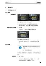
Page 99: ...4 机器简介 26 4 6 数字式转速 小时 数字感应式转速 小时能够显示三个值 运转时数 发动机熄火 实际转速 发动机运转时 曾经达到的每分钟转速最大值 图 11 例 实际 rpm 显示 1 按钮 4 7 配件 轨道移动指示器 EDP 编号 886 823 0001 图 12 轨道移动指示器 ...

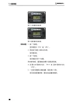
Page 100: ... 转速 小时显示实际运行时间 当发动机运转时 转速 小时显示发动机的实际转速 1 按 2x 键 显示器显示 2 RPM 和存储的 RPM 最大值 图 14 每分钟存储的 RPM 最大值 如果没有按下按钮约 8 秒 显示器自动切换回标准模 式 5 1 2 设置 数字转速 小时已根据所用的发动机设定出厂 设置 不得无故更改设置 数字转速 小时既可用于二冲程发动机 也可用于四冲程发动 机 1 按一下按钮 如果使用二冲程发动机 则应该显示 1P1r 如果 使用四冲程发动机 则应该显示 2P1r 显示标准模式 查看存储的 RPM 最大值 检查设置 ...

Page 101: ...15 二冲程发动机设置 图 16 四冲程发动机设置 1 按一下按钮 显示器显示 1P1r 或 2P1r 2 再次按下按钮 保持大约 4 秒 显示器闪烁 3 按一下按钮 显示器显示另一个设置 再次按下按钮 显示器就会在两个设置之间切换 4 设 置 二 冲 程 发 动 机 为 1P1r 或 四 冲 程 发 动 机 为 2P1r 5 一旦显示器显示正确的设置 等待大约 10 秒 显示的设置已被存储 显示自动返回标准模式 更改设置 ...

Page 102: ...调整化油器设置 它将显示 低性能 且容易过热 并最终因混合气过于稀薄而遭受严重 损坏 根据该高度调整化油器设置 不得无故更改化油器的设置 5 2 1 高空作业 800 米 在海平面以上的高海拔地区 燃料 空气的混合物会变得过于 浓稠 因为空气中氧含量较低 这会导致发动机性能下降和 油耗增加 工具 螺丝刀 1 启动发动机并让它预热 2 握紧捣固机 使捣固机不接触地面 3 加全油门并评估发动机的声音 如果发动机运转不畅 则 表明混合气太浓 4 顺时针方向转动螺钉 H 2 每一步旋转 1 8 圈 如下 图所示 图 17 螺钉 L 1 和 H 2 高海拔下化油器的设置 ...

Page 103: ...整 如 果需要进一步调整 继续转动螺钉 L 1 顺时针旋转 每 一步转动 1 8 圈 化油器已设定好 可在高海拔地区使用 即使在适当的化油器设置下 海拔高度每增加 305 米 1000 英尺 发动机马力仍会降低大约 3 5 如果化油器设置不 进行调整 海拔高度对马力的影响将比这更大 如果发动机在较低的高度运行 请确保再次 调整设置 5 2 2 低空作业 100 米 在低海拔高度下 MSL 平均海平面 燃料 空气的混合物会 变得很差 这会导致发动机性能下降和过热 进而导致发动机 损坏 工具 螺丝刀 1 启动发动机并让它预热 2 握紧捣固机 使捣固机不接触地面 3 加全油门并评估发动机的声音 如果发动机运转不畅 则 表明混合气太差 4 逆时针方向旋转 H 2 螺钉 每一步旋转 1 8 圈 如下 图所示 低海拔下化油器设置调整 ...

Page 104: ...果需要进一步调整 继续按顺时针方向旋转螺钉 H 2 每一步转动 1 8 圈 6 让发动机空转 评估发动机的声音 如果发动机运转不畅 则表明混合气太差 7 逆时针旋转螺钉 L 1 每一步转动 1 8 圈 8 评估发动机的声音 如果发动机运转平稳 完成调整 如 果需要进一步调整 继续转动螺钉 L 1 逆时针旋转 每 一步转动 1 8 圈 化油器已设定好 可在低海拔下使用 发动机高空运行之前确保再次调整化油器的 设置 5 2 3 怠速调整 当混合气已根据高度设置后 可能需要重新调整怠速设置 参 见第 9 3 4 章 ...

Page 105: ...重损坏 确保发动机运行时有足够的机油 发动机停机后在水平地面检查机油油位 1 将发动机水平放置 油箱侧面朝下放在水平面上 2 拆下加油口盖 检查油位 确保油位高于油箱的下限标志 图 19 发动机油位 1 机油 2 上限标记 3 下限标记 3 如果油位低 加建议的油直至到达油箱上限标记 4 每 10 个运行小时检查油位并加建议的油直至到达油箱上 限标记 四冲程发动机使用的发动机油应满足或超过 API 美国石油协 会 使用类级 SF 或以上要求 或同等质量 始终检查机油 容器上的 API 使用标签 以确保它包含字母 SF 或更高类级 或同等质量 的字母 ...

Page 106: ... 如果使用地点的平均温度在 规定范围内 则可以使用表中给出的其他粘度的机油 通知 发动机损坏风险 使用不合适的机油会对发动机的使用寿命产生不利影响 不要使用不溶性油或二冲程油 图 20 SAE 粘度类别 1 SAE 粘度类别 2 环境温度 5 3 2 空气过滤器 通知 发动机损坏风险 如果发动机在没有空气过滤器的情况下工作 颗粒物 灰尘 会进入燃烧室 导致发动机磨损 套筒结构会被刮伤 发 动机将丧失压缩功能 进而导致性能下降 没有空气过滤器时切勿运行发动机 ...

Page 107: ...空气过滤器 敏感的滤芯可能会被 破坏 刷力会使污垢渗入纤维 不要使用压缩空气来清洗或干燥空气过滤器 不要用刷子来清除污垢 Robel 建议定期更换空气过滤器和火花塞 以 符合维护计划表中的规范要求 只有在紧急情况下 即在没有备用部件的情 况下 才对空气过滤器和火花塞执行所描述 的清洁程序 1 检查空气过滤器滤芯以确保其洁净且状态良好 2 必要时清洗或更换滤芯 图 21 空气过滤器 1 固定螺栓 2 滤芯 纸 3 回线 4 滤板 5 分离板 6 滤芯 海绵 7 空气过滤器盖 ...

Page 108: ...的热量会导致燃料膨胀 并通过 加油口盖的开口泄漏 油箱不要加得太满 加油颈不得有燃油 通知 发动机损坏风险 燃料污染会导致发动机损坏 不要使用任何不清洁的机油 汽油混合物或汽油 避免污垢 灰尘或水进入油箱 使用清洁 新鲜且无铅的汽油 乙醇含量百分比不超过 10 油漆涂层有损坏的风险 燃料会腐蚀油漆和一些塑料制品 加油时一定不要把燃料洒了 1 保持手柄干燥 清洁 无燃油和油污 2 将振动式捣固机放在手柄架上 拧下油箱盖 3 小心加油 油箱容量 0 6 升 4 旋回油箱盖 并检查它是否紧密贴合 5 如果油箱盖有任何损坏 请更换 不要使用储存超过两个月的汽油 ...

Page 109: ...5 机器准备 36 图 22 油箱加油 1 油箱盖 2 燃料上限 3 燃油箱 ...

Page 110: ...6 操作 37 6 操作 6 1 启动发动机 1 当发动机处于低温状态时 关闭阻风门杆 将其滑动至关 闭位置 如果发动机有点热 则完全打开 油门手柄 使用简便 使发动机可以更好地启动 图 23 关闭阻风门杆 1 阻风门 关闭 位置 2 继续推动起动注油泵 直到燃料进入该泵 一般推 7 到 10 次 图 24 起动注油泵 1 起动注油泵 ...

Page 111: ...后立即放开起动器手柄 则该手柄可能损坏 不要让起动器手柄回弹到发动机上 而要小心地将其向 后移动 3 轻拉起动器手柄 直到感觉到阻力 然后用力拉出手柄 4 发动机启动后 将阻风门杆设置为开启位置 检查发动机运行的同时逐渐打开阻风门杆 最后一定要把阻风门杆完全打开 在寒冷条件下或发动机冷却后 切勿突然打 开阻风门杆 否则发动机可能会熄火 图 25 将阻风门杆移动到 开启 位置 1 阻风门 开启 位置 5 将发动机预热 2 3 分钟 同时不时拉动油门手柄 ...

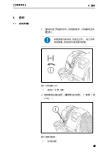
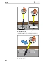
Page 112: ... 与捣固机一起工作 6 2 1 捣固 轨枕 避免与轨枕接触 将捣固机具放置在轨枕附近约 1 5 厘米处 捣固时捣固机具不要碰到轨枕 施加符合人体工程学的力量 在捣固的时候 用您身体上部的重量来施 加垂直的力量 这样可以放松您的脊柱 1 保持捣固机直立 并将其放置在轨枕旁边 2 用手压下油门手柄 捣固机具开始振动 3 继续用手柄把持住捣固机 并利用身体上部的重量施加力 4 垂直潜入道碴直到捣固机具到达轨枕底部以下约 5 到 10 厘 米处 见图 ...

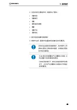
Page 113: ...6 操作 40 图 27 捣固机具与轨枕间距 5 将捣固机拉向操作人员 以便将道碴压实在轨枕之下 图 28 压实轨枕下的道碴 距离 1 5 厘米 距离 5 10 厘米 ...

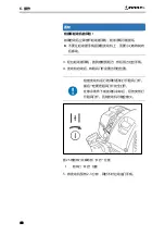
Page 114: ...6 操作 41 6 撤回捣固机 7 重复第 1 6 步 2 到 3 次 以获得最佳和可持续的效果 8 最后 在不进行任何操作的情况下插入捣固机 并将捣固 点的凹痕整平 不要把捣固机放在离轨枕太近的位置 最小 距离 1 厘米 9 在轨枕的两侧重复这一步骤 图 29 在轨枕的两侧重复这一步骤 ...

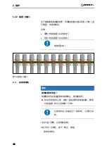
Page 115: ...最佳的捣固效果 所有轨枕都必须从两侧 方向 进 行捣固 向前和向后 示例 绿色 向前捣固 从右到左 红色 向后捣固 从左到右 或者反过来 图 30 捣固 轨排 6 3 关停发动机 通知 发动机损坏风险 如果发动机在高速运转时突然停止 就可能损坏 在关闭发动机之前 如其一直在满负荷高速运转 降低 它的速度 并让它空转约一分钟 让发动机以怠速运行一段时间 以便它冷 却 1 松开油门手柄 让发动机空转 2 在大约 1 分钟后 按下 停止 按钮 发动机停机 ...

Page 116: ...6 操作 43 6 4 安装轨道移动指示器 配件 当火车在轨道上行驶时 可以用轨道运动指示器来显示轨道的 运动 图 31 轨道移动指示器 1 指示器部分 2 刻度盘 3 刻度盘部分 4 箭头 5 夹紧杆 1 从轨道下面移除道碴 2 松开指示器部分的夹紧杆 3 将指示器部分压入轨道下 并用夹紧杆将其固定在轨道上 4 将刻度盘置于红色箭头的正对面 火车一行经轨道 动作就可以从刻度盘上的箭头读出 ...

Page 117: ...7 运输与储存 44 7 运输与储存 通知 有损坏的风险 机油比发动机还高的时候 就会从捣固机中泄漏出来 因此运输立式捣固机时其电机应始终朝上 7 1 运输 运输机器的温度范围是 20 到 60 如果将产品放在原始包装中并妥善捆扎 则可以通过任何运输 方式运输而不受损坏 1 将立式捣固器送至作业站 图 32 搬运立式捣固机 运输到作业站 ...

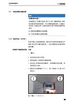
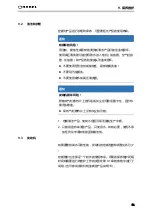
Page 118: ...放下机器 7 2 储存 机器的储存温度范围为 20 至 60 确保储存处干燥无尘 通知 有损坏的风险 机油比发动机还高的时候 就会从捣固机中泄漏出来 存放立式捣固机时其电机应始终朝上 1 确保储存的地方没有过多的水汽和灰尘 警告 有着火或爆炸的危险 汽油是极易燃的 在某些条件下是易爆的 遵守第 2 章有关内燃机和燃料的安全须知 2 放空燃油 3 确保加油口盖牢固地拧紧 4 拧下油箱盖并将燃油排入合适的容器 为此目的发动机应 向加油颈倾斜 5 如果油箱里还有异物 应完全去除 放下机器 机器长期存放之前 ...

Page 119: ...7 运输与储存 46 6 用金属丝从加油口拉出燃油过滤器 7 多次按下起动泵按钮 直到燃料回流管路中的所有燃料被 泵回油箱为止 8 将发动机向燃料加注口颈部倾斜 使油箱中的燃料流到容 器中 9 将滤清器放入油箱 并牢牢拧紧油箱盖 10 然后 继续操作发动机 直至它停机 11 拆下火花塞 从火花塞孔中滴入几滴机油 12 轻拉起动器手柄 以便发动机油分散到发动机上 然后固 定火花塞 ...

Page 120: ...转停机 怠速设置过低 调整怠速设置 参见第 9 3 4 章 发动机变得很热 性能很低 化油器设置过稀 根据海平面以上的实际高度 调整化油器设置 参见第 5 2 章 燃油过滤器堵塞 清洁燃油过滤器 参见第 9 3 2 章 油位过低 检查油位 参见第 5 3 1 章 发动机运转不畅 性能低下 化油器设置太浓 根据实际海拔高度调整化油 器设置 参见第 5 2 章 燃油过滤器堵塞 清洁空气过滤器 参见第 9 3 1 章 捣固机具磨损 磨损 更换捣固机具 参见第 9 5 章 捣固镐轴承磨损 磨损 更换轴承 参见第 9 6 3 章 橡胶缓冲器开裂 磨损 更换橡胶缓冲器 参见第 9 4 章 捣固镐不振动 虽然发动机高速 运转 发动机与偏心轴间的连接件有缺 陷 更换连接件 参见第 9 6 3 章 ...

Page 121: ...请关掉发动 机 在进行维护工作之前 一定要断开火花塞 连接器 以防止发动机意外启动 小心 有灼伤的危险 发动机 尤其是消音器和机器部件 在运转 过程中会发热 请勿触摸发热部位 在进行维护工作之前 让机器至少冷却 30 分钟 通知 发动机损坏风险 如果所使用的备件不符合规定的质量要求 就有损坏发动机 的风险 只使用原装零部件或同等规格的零部件 1 只使用推荐的润滑剂 在进行维修时 只使用原装备件 这一点首先对于质保很重要 其次也有助于提高产品 的运行可靠性 正确订购备件无论对于快速交付备件 还是对于实现 产品的经济可行性 都必不可少 ...

Page 122: ...订购备件时 请提供以下资料 机器类型 机器编号 组装 备件描述和编号 数量 运输方法 发货地址 3 遵守规定的保养间隔周期 4 维修作业时 要遵守相应国家规定的安全和环保规例 发动机应由授权经销商维护 除非操作人员 拥有必要的工具和维护数据 并具备必要的 技术知识和技能 Robel 建议定期更换空气过滤器和火花塞 以 符合维护计划表中的规范要求 只有在紧急情况下 即在没有备用部件的情 况下 才对空气过滤器和火花塞执行所描述 的清洁程序 ...

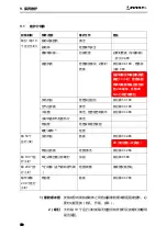
Page 123: ...并用 20 Nm 力矩拧紧螺钉 发动机油 检查加注油位 参见第 5 3 1 章 空气过滤器 清洁 参见第 9 3 1 章 火花塞 清洁 检查是否有损坏 参见第 9 3 3 章 冷却风道和气缸散热片 清洁 燃油管 检查安装是否紧固 螺钉 螺母 2 检查 每 50 个 运行小时 发动机油 替换 参见第 9 3 4 章 20 小时后第一次换油 燃油过滤器 检查 清洁 参见第 9 3 2 章 每 100 个运 行小时 离心式离合器止动螺钉 加油 参见第 9 5 章 每 200 个运 行小时 气门间隙 进气阀和排气阀 检查 调整 请求授权服务站 每年或每 200 个运行 小时 燃油管 替换 参见第 9 3 7 章 安装在导向架和振动体之间的减振橡胶缓冲器是易磨损件 必 要时必须更换 砂孔 开裂 损坏 大约每 10 个运行小时或每天检查所有外部可及的螺钉和螺母 是否紧固 1 橡胶缓冲器 2 螺钉 ...

Page 124: ...气过滤 器 化油器 和产品的铰接接头而造成损坏 不要使用任何溶剂或腐蚀性 易燃的清洗液 不要用汽油清洗 不要使用喷水或高压清洗器 通知 发动机损坏风险 附着在气缸散热片上的污垢或灰尘会导致活塞卡住 因为热 量无法散逸 保持气缸散热片上没有灰尘和污物 1 定期清洁产品 使其不会因污垢而造成生产中断 2 只能用湿布来清洁产品 只使用水 如有必要 使用不添 加任何化学添加剂的温和清洁剂 9 3 发动机 如果要维持高水平的性能 发动机的定期检查和调整必不可少 定期维护也会保证一个较长的使用寿命 所需的保养维护间隔 时间和需要进行的维护工作的类型在第 9 1 章的表格中进行了 说明 也可参阅发动机制造商的产品说明书 ...

Page 125: ...的危险 如果用汽油或低闪点溶剂清洗空气过滤器 可能会发生火灾或爆炸 不要使用汽油或低闪点溶剂清洗空气过滤 器滤芯 通知 发动机磨损加剧的风险 如果发动机在没有空气过滤器的情况下运行 颗粒物 灰尘 易进入燃烧室 发动机活动部件 活塞和气缸 出现划痕 发动机会失去压缩功能 进而丧失其性能 没有空气过滤器时切勿运行发动机 通知 有损坏空气过滤器的风险 如果使用压缩空气来清洗空气过滤器 敏感的滤芯可能会被 破坏 刷毛会使污垢渗入纤维 不要使用压缩空气来清洗或干燥空气过滤器 不要用刷子来清除污垢 空气过滤器备件 纸滤芯 EDP 编号 900 044 0398 海绵滤芯 EDP 编号 900 044 0456 ...

Page 126: ...时 每天 清洗一次空气过滤器 1 关闭阻风门杆 移动到关闭位置 图 34 空气过滤器 1 固定螺栓 2 滤芯 纸 3 回线 4 滤板 5 分离板 6 滤芯 海绵 7 空气过滤器盖 2 压下壁板 4 上的环箍 3 松开空气过滤器盖上的卡 扣 3 松开固定螺栓 1 4 拉下空气过滤器盖 7 5 拆下滤芯 2 6 轻拍滤芯以去除污垢 对于重污染 6 取出滤芯 海绵 放入温水或用水稀释的中性洗涤剂中 7 使之充分干燥 8 清洗时不要挤压或摩擦它 ...

Page 127: ...清洗元件 钩住卡夹并固定固定螺栓 以重新安 装空气过滤器盖 11 紧固固定螺栓 9 3 2 清洗燃油过滤器 警告 有着火或爆炸的危险 汽油是极易燃的 在某些条件下是易爆的 禁止在工作区域吸烟或允许产生火焰或火 花 1 确保四冲程发动机的机油加油口盖牢牢紧固 2 拧下油箱盖 3 用金属丝小心从加油口颈拉出燃油过滤器 图 35 清洁燃油过滤器 1 燃油管 2 软管夹 3 燃油过滤器 4 检查燃油过滤器是否有任何污染 如果它被污染了 用不 易燃的溶剂或高闪点的溶剂清洗 如果过滤器遭过度污染 请更换 ...

Page 128: ...重新插入到加油口颈 7 将过滤器一直推到油箱的底部 8 拧紧油箱盖 图 36 过滤器位置 1 燃油过滤器 9 3 3 火花塞维护 为了确保发动机正常运转 火花塞必须有适当的间隙且无沉淀 通知 发动机损坏风险 如果使用的火花塞的热范围不够 发动机可能会损坏 使用具有足够热范围的火花塞 推荐火花塞 CMR6A NGK 火花塞备件 EDP 编号 900 044 0408 该推荐火花塞具有正确的热额定值 可确保发动机有正常的运 行温度 1 拆下火花塞连接器 2 清洁火花塞周围区域 3 用合适的火花塞扳手拧下火花塞 ...

Page 129: ...来进行必要的校正 火花塞间隙 2 0 70 0 80 毫米 0 028 0 031 图 37 火花塞间隙 1 密封垫圈 2 火花塞间隙 通知 发动机损坏风险 一个松动的火花塞可能会变得非常热 火花塞过紧可能损坏 气缸盖的螺纹 将火花塞拧紧至规定扭矩 7 确保密封垫圈合乎要求 然后用手将火花塞旋回 避免螺 纹错扣 安装一个新的火花塞时 在火花塞就位后拧 紧 圈 以压紧密封垫圈 重新安装原来的火花塞时 在火花塞阀座后 拧紧 1 8 到 1 4 圈 以压紧密封垫圈 8 火花塞就位后 用火花塞扳手拧紧火花塞 压紧密封垫圈 9 重新安装火花塞连接器 ...

Page 130: ... 怠速调整 1 启动发动机并进行预热 2 将油门杆推至 MIN 位置 工具 螺丝刀 图 38 螺钉 T 怠速 如果怠速过高 则转动螺钉 T 1 ccw 如果怠速太低 发动机停止 则转螺钉 T 1 cw 空转速度的标称值 大约每分钟 1100 RPM 9 3 5 将化油器复位到出厂设置 如果在化油器上进行多次更改都没有成功 那么将化油器重置 为原始设置并从此时重新开始调整可能会有效果 工具 螺丝刀 图 39 螺钉 L 1 和 H 2 ...

Page 131: ...完全拧紧 CW 然后向相反方向转动 2 圈 CCL 化油器的出厂设置已经恢复 适用于海拔 400 米 MSL 9 3 6 换油 警告 有受伤的危险 皮肤与旧机油反复长时间接触可能会导致皮 肤癌 戴上防护手套 每次接触用过的油后立即用水和肥皂彻底 洗手 以符合环保规例的方式处置用过的发动机油 不要把用过的油和垃圾一起倒在地上或排入 下水道 我们建议您装在专门的容器里并密封 然后 送到您当地的废油处理机构 在发动机仍处于温热状态时排放机油 以确 保快速和彻底的排放 1 确保油箱盖牢固拧紧 2 放置一个大容器 盘等 ...

Page 132: ...维护 59 图 40 换油 3 拆下油箱盖 将捣固机向加油孔倾斜 然后排出机油 收 集容器里的机油 4 加推荐用油 SAE 15 W 40 并检查油位 5 重新装上加油口盖 发动机加油量 大约 0 06 升 9 3 7 更换燃油管 警告 有发生火灾和爆炸的风险 汽油是极易燃的 在某些条件下是易爆的 燃油泄漏会引起火灾 如果在检查过程中发现任何泄漏 应立即 更换燃油管 遵守第 2 章关于内燃机和燃料的安全信息 ...

Page 133: ...9 保养维护 60 图 41 燃油管 1 燃油管 1 每年或每 200 个运行小时更换燃油管 2 如果在检查过程中发现任何泄漏 应立即更换燃油管 ...

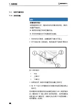
Page 134: ...9 保养维护 61 9 4 橡胶缓冲器 9 4 1 检查橡胶缓冲器 安装在手柄 安装板和捣固机具之间的减振橡胶缓冲器为易磨 损件 1 必要时更换橡胶缓冲器 可见的裂纹 砂孔 图 42 橡胶缓冲器 1 手柄和安装板之间 4x EDP 编号 988 015 0446 2 安装板和捣固机具之间 4x EDP 编号 900 162 0104 不要重复使用用过的六角螺母 EDP 编号 990 985 1000 ...

Page 135: ...橡胶缓冲器 工具 开口扳手 AF 17 护嘴钳 通知 有损坏橡胶缓冲器的风险 如果橡胶缓冲器扭曲或错位 则会在静止状态下产生拉应力 或压应力 正常运行过程中再加应力 这将导致橡胶缓冲器 所受应力过大 进而导致橡胶缓冲器的使用寿命显著缩短 如果用钳子夹住橡胶缓冲器而没有额外的保护 就会损坏 橡胶缓冲器不得拧至扭曲和错位 如果您出于保护目的用钳子夹住橡胶缓冲器 则需要采 取额外的保护措施 图 43 左 扭曲的接缝 右 竖缝 拆卸橡胶缓冲器 ...

Page 136: ...9 保养维护 63 1 用钳子将橡胶缓冲器固定 拧紧相关螺母 扭矩 20 纳米 图 44 安装橡胶缓冲器 1 橡胶缓冲器 2 夹钳 3 保护装置 9 5 离心式离合器 每 100 个运行小时 1 拧下止动螺钉 1 重新注入大约 2 立方厘米的滚珠轴 承润滑脂 图 45 离心式离合器维护 1 止动螺钉 2 旋入止动螺钉 安装橡胶缓冲器 ...

Page 137: ...机具 9 6 1 检查捣固机具的磨损情况 为防止捣固镐底部出现一个孔洞 防止漏油或轴承损坏 必须 在每次使用前进行例行检查 看看材料的磨损程度 通知 捣固镐有损坏的风险 捣固机具磨损 捣固镐铝管可见 有形成孔洞的危险 一旦看到铝管 就必须更换捣固机具 图 46 捣固机具长度测量 1 用卷尺测量捣固机具的长度 新型捣固机具 长度 40 5 厘米 捣固机具磨损 长度 36 厘米 2 一旦捣固机具磨损约 4 5 厘米 必须更换 见下一页 ...

Page 138: ...9 保养维护 65 9 6 2 更换捣固机具 工具 材料 开口扳手 AF 13 扭力扳手 角磨机 捣固机具拆卸装置 可选 如果捣固机具磨损 很可能螺钉和螺母也损 坏了 在这种情况下 无法借助标准工具来 拆除紧固螺钉 图 47 切断螺钉 1 用角磨机切断两个螺钉 见箭头 每一侧各一个螺钉 图 48 捣固机具拆卸装置 可选 1 捣固机具拆卸装置 2 捣固机具支架 拆除旧捣固机 ...

Page 139: ... 3 六角形接收装置 订购编号 捣固机具拆卸装置 EDP 编号 8998950200 2 将捣固机具放置在捣固机具拆卸装置 可选 的支架 2 上 3 使用合适的扳手逆时针方向转动捣固机具拆卸装置的六角 形接收装置 3 4 从捣固镐上拆下捣固机具 1 测量捣固镐的长度 并将其标记为 34 5 厘米 图 49 标记捣固镐 安全设备 防护手套 安全护目镜 呼吸面罩 图 50 安全设备 滑动式新型捣固机具 注入树脂延长使用寿命 ...

Page 140: ...9 保养维护 67 图 51 交货范围 1 注射针管 环氧树脂 2 转接器 3 混合管 4 口罩 5 防护手套 6 辅助板 注意数据表及安全数据表 工具 装置 材料 多用途润滑脂 刷子 纸巾 锉刀 侧铣刀 ...

Page 141: ...9 保养维护 68 2 在铝管底部 200 毫米处涂上多用途润滑脂 并将其涂在定 心处 用润滑脂作为脱模剂 使铝管不与捣固机具连接 图 52 在铝管和定心处涂上润滑脂 3 擦去多余的多用途润滑脂 图 53 擦去多余的润滑脂 ...

Page 142: ...9 保养维护 69 4 准备注入 图 54 拆下保护盖 图 55 固定转接器 拧下混合管 缩短混合管 ...

Page 143: ...9 保养维护 70 5 在捣固机具上放置辅助板 并将注射针管插入辅助板 图 56 将辅助板放置在捣固机具上 图 57 将注射针管插入辅助板 ...

Page 144: ...9 保养维护 71 6 将环氧树脂注入捣固机具中 图 58 将环氧树脂注入捣固机具 加注时 确保环氧树脂正好在捣固机具的底 部 7 拆下注射针管和辅助板 8 在 2 分钟内将捣固机具推到铝管上并检查控制尺寸 224 毫 米 参见第 9 1 章 图 59 将捣固机具推到铝管上 9 使用 AF13 扳手和扭力扳手 将螺母拧紧到六角螺钉上 ...

Page 145: ...9 保养维护 72 10 均匀拧紧两侧的 2 颗螺钉 每个螺钉 20 Nm 图 60 拧紧固定螺钉至 20Nm 11 检查捣固机具与捣固镐法兰之间的距离 见下图 测量目标 224 毫米 图 61 基准测量检定 12 竖直存放约 5 小时 让树脂硬化 ...

Page 146: ...上 该轴套与捣 固机具的阀座紧密配合 因此需要相当大的力才能拆卸偏心轴 工具 装置 材料 敲击装置 EDP 编号 899 895 0001 放油盘 容器 开口扳手 AF 17 内六角扳手 AF6 60 毫升发动机油 SAE 10W 30 通知 有损坏捣固镐的风险 如果捣固镐的法兰或轮彀被任何工具直接撞击 则捣固镐很 可能会遭扭曲和不可逆转的损坏 如此则无法卸下偏心轴 使用敲击装置 1 可选 拆卸偏心轴 通知 排油污染风险 捣固镐加的有机油 因此拆卸时应放油 准备好在拆卸过程中放油 我们建议在合适放油盘 最 好是钢制的 上方进行偏心轴的拆卸 1 提供一个放油盘 最好是钢制的 放油盘需足够大 以承 接敲击装置 1 偏心轴拆卸 ...

Page 147: ...击装置 可选 7 浮动轴承套 2 中间轴 8 不平衡 3 橡胶减震装置 9 偏心轴 4 固定轴承 10 捣固镐法兰 5 捣固镐 11 螺母和螺栓 M10 6 浮动轴承 12 发动机轴紧固螺钉 图 64 敲击装置 敲击装置的订购编号 EDP 编号 899 895 0001 2 拆下立式捣固器的整个总成 捣固镐 用开口扳手 AF17 拧松法兰 10 的 M10 11 螺钉 然后用内六角 扳手 AF6 将连接件连接到发动机轴 橡胶波纹管下 的两 个 M8 12 螺钉拧松 ...

Page 148: ...离出来 7 中间轴的外连接件接触工作表面后 将偏心轴连同轴承一 起抽出 排出机油 大约 60 毫升 8 拆卸敲击装置 9 更换轴承 安装偏心轴 通知 有损坏捣固镐的风险 在捣固镐的内侧 浮动轴承套有一个止动块 限制了装配过 程中的行程 如果施加力 虽已经达到该止动块 轴承仍可 能损坏 装配过程中考虑 74 毫米的尺寸 一旦到达这个尺寸 不 要施加任何更多的力 较低的轴承 浮动轴承 需要加油 以达到一个较长的工作 寿命 请务必加适量的发动机油 60 毫升 10 将捣固镐置于法兰朝上的位置 注入 60 毫升发动机油 11 首先用浮动轴承将偏心轴插入捣固机 直到轴承套接触到 它们的阀座 12 将捣固镐置于坚硬的工作表面上 法兰朝上 然后用力敲 击工作表面数次 惯性将驱动偏心轴进入捣固镐 ...

Page 149: ...用螺钉 2 捣固镐法兰 3 中间轴 13 考虑 74 毫米的尺寸 继续敲击 直到达到这个尺寸为止 14 在装配之前 检查发动机和中间轴之间的连接件 3 的 定位是否正确 必要时对齐 15 接入捣固镐和发动机 16 将螺钉插入法兰并拧紧 17 去除固定中间轴连接件与发动机轴 橡胶波纹管下 的两 个螺钉上的油脂 并运用高强度螺钉固位 18 插入发动机轴的两个螺钉 1 并用 20Nm 拧紧 9 7 标志和标签 定期检查标志和标签是否完好 必要时更换标志和标签 74 mm ...

Page 150: ... 和适当回收 处置的法律规定 并遵守使用者所在国家适 用的环境法 2 特别要注意的是 在维修和保养工作中 应确保水污染物 质 如油脂和机油 不得污染地面或进入下水道 10 2 处置 该产品 包括机械零件 发动机油和燃料 的处理将取决于当 地的废物处理条例 产品寿命周期结束时 应确保进行安全和适 当的处理 特别是对环境有害的部件或物质 的处理 其中包括燃料 润滑剂和塑料 1 由于存在潜在的环境污染的风险 应将产品交给经批准的 专业公司处理 2 在任何情况下 检查哪些材料可用于回收利用 并将这些 材料交由适当的废物管理公司处理 ...

Page 151: ...11 附录 78 11 附录 图 66 欧共体符合性声明 欧共体符合性声明 ...

Reviews: