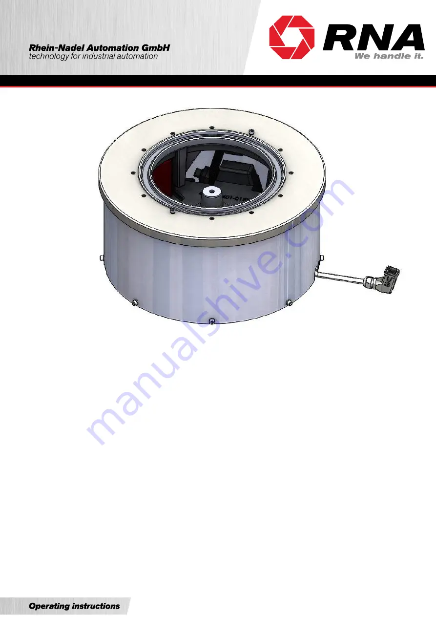
Installation and Operating Instructions
Vibratory Feeders
SRC-N 160-2 SRC-N 200-2
SRC-B 200-2
SRC-N 250-2
SRC-B 250-2
SRC-N 400-1 SRC-N 400-2 SRC-N 630-1 SRC-N 800-1
SRHL 400-1 SRHL 400-2
Page 1: ...Installation and Operating Instructions Vibratory Feeders SRC N 160 2 SRC N 200 2 SRC B 200 2 SRC N 250 2 SRC B 250 2 SRC N 400 1 SRC N 400 2 SRC N 630 1 SRC N 800 1 SRHL 400 1 SRHL 400 2...
Page 2: ...data 4 2 Safety directives 7 2 1 Applicable directives and standards 8 3 Design and functional description 8 4 Shipment and installation 10 5 Commissioning 12 5 1 Feeder speed decreases 13 5 2 Feeder...
Page 3: ...ow Voltage Directive 2014 35 EU We hereby declare that the product meets the following requirements Low Voltage Directive 2014 35 EC Applied harmonised standards DIN EN 60204 T1 Remarks We assume that...
Page 4: ...5000714 WZUW 080 35000721 WZUW 080 35000721 WZAW 060 35000727 WZAW 060 35000727 YZAW 080 35000739 Magnet colour black black black black black red Air gap mm 0 3 0 5 0 4 0 5 0 4 0 5 1 1 2 1 1 2 2 3 2 8...
Page 5: ...5 0 5 0 5 1 4 Power input2 VA 786 1140 1060 1000 1700 Current 2 A 4 05 5 7 5 3 5 8 5 Nominal magnet voltage 2 frequency 220V 50Hz Number of magnets 3 2 2 4 4 Magnet type Article number WZAW 080 350007...
Page 6: ...Rhein Nadel Automation GmbH 6 VT MA SRC 160 800 EN_2019 20 03 2019 SJ Pin assignment With jumper The jumper must be inserted between connections 3 4...
Page 7: ...ludes observance of the operating instructions and compliance with the maintenance rules For the technical data for your vibratory feeder please refer to the table Technical Data Section 1 Make sure t...
Page 8: ...enting parts The driving force is provided by an electromagnetic coil The figure below is a schematic representation of a vibratory feeder Driving magnet D is rigidly connected to counter mass F When...
Page 9: ...200 SRC N 250 SRC B 250 SRC N 400 SRHL 400 SRC N 630 SRC N 800 The controller has a 5 pin connector on its front panel for connection to the vibratory feeder Connector pin assignment is shown in the...
Page 10: ...plastic cap and domed nut M16 Attention Do not sling or handle the vibratory feeder at or on the orienting device Take care that the vibratory feeder cannot collide with other objects during handling...
Page 11: ...20 3 x 120 M 8 SRC B 250 220 3 x 120 M 8 SRC N 400 1 350 3 x 120 M 10 SRC N 400 2 350 3 x 120 M 10 SRHL 400 1 350 3 x 120 M 10 SRHL 400 2 350 3 x 120 M 10 SRC N 630 1 560 3 x 120 M 10 Table Drilling d...
Page 12: ...r vibratory feeders that are supplied as a completely set up system the optimum feed rate has been fac tory set It is marked with a red arrow on the dial of the rotary knob In this case set the rotary...
Page 13: ...0 5 2 Feeder speed increases Remove springs Start by removing one spring including spacers from one spring pack If the feeder speed continues to increase after you loosen a fastening screw anew remove...
Page 14: ...missible sound insulating hoods can be installed which we can offer on request see our catalogue 6 Maintenance Vibratory feeders basically require no maintenance They should only be cleaned when soile...
Page 15: ...ctor there is a risk of damage to the controller and magnet Set controller to 80 Check that coding in plug connector of the controller is correct see rating plate and Technical Data Section 1 The vibr...
Page 16: ...uk com www rnaautomation com Manufacturing and Sales HSH Handling Systems AG Wangenstr 96 CH 3360 Herzogenbuchsee Switzerland Phone 41 0 62 956 10 00 Fax 41 0 62 956 10 10 E mail info handling systems...