background image


Safety reliably produced. 

© RLS Wacon analytics GmbH ∙ +49 (0)5121 28126 0 ∙ 

[email protected]


Subject to 

change without notice


36 

Operation and handling


Operating principle 

The LIMES based on the SYCON series is an online analyser for the automatic determination of 
total hardness according to the colorimetric limit value method. By adding a reagent to the water 
sample, a colour reaction is generated. Depending on the reagent used, the device evaluates the 
intensity of the colour. By the colour change of the sample after the addition of the reagent, the 
LIMES monitors the limit value of the water ingredient. The limit value is determined by the 
reagent used. 
 

Analysis process 

The analysis procedure consists of several steps. The duration of each step depends on the 
configuration of the unit. The first analysis is started automatically 3 minutes after switching on. 
If the limit value is undershot, the next analyses are carried out at the set analysis interval. The 
set analysis interval time can only be adhered to if the rinsing time is not set to be longer than 
the interval time. In the event of a limit value being exceeded, the following measurements are 
carried out at 8-minute intervals to promptly indicate that the system is ready again after 
regeneration. 
The analysis takes 3 minutes plus the set flush time. A control measurement takes place 4 
minutes after completion of the first measurement (first value suppression). A control 
measurement (first value suppression) is permanently integrated in the LIMESBase and 
LIMESPlus programme sequence. 
 

Operation with hot sample water 

When monitoring hot water, the sample must be cooled to below 40 °C (< 104 °F).  
 

Rinsing the measuring chamber and taking the water samples 

The inlet solenoid valve opens. The measuring chamber and the supply line are flushed until it is 
ensured that there is water from the process to be monitored in the measuring chamber. With 
the LIMESPlus, the flushing time can be adjusted to the length of the supply line. 
 

Measurement of the zero sample 

A zero sample is always taken before the actual measurement begins. The zero sample is used to 
determine influencing disturbance variables such as sample turbidity, contamination of the optics 
or extraneous light influences and to be able to take them into account for the evaluation of the 
water sample. The actuator LED lights up during this process. The solenoid valve is open during 
the zero sample. 
 

Dosing the reagent into the water sample


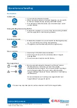
The solenoid valve on the device is closed and the reagent is dosed into the water sample. By 
turning the stirring blade, the reagent is homogeneously dissolved in the water sample.  


Summary of Contents for 32-074165

Page 1: ...Safety reliably produced Operating instructions LIMES Hardness control device for automated monitoring of total hardness in the process water...

Page 2: ...Safety reliably produced RLS Wacon analytics GmbH 49 0 5121 28126 0 info rls wacon de Subject to change without notice 2...

Page 3: ...Overview of the electrical connections junction box 25 Establishing the supply voltage with junction box 26 Establishing the supply voltage without junction box 26 Connecting the relay outputs 27 Conn...

Page 4: ...ristaltic pump cash register 55 Component exchange 56 Diagnostic functions LIMESPlus 59 Diagnostic functions LIMESBase 64 Spare parts 65 Maintenance sets and accessories 67 Maintenance sets 67 Accesso...

Page 5: ...and instructions in this manual may differ from your actual purchased unit We reserve the right to make technical changes without prior notice On our website www rls wacon de you will always find the...

Page 6: ...n triggering can be realised The LIMES analyser is characterised by low maintenance costs Up to 10 000 analyses can be carried out with a 750 ml reagent bottle The input contact of the device can addi...

Page 7: ...ogramming may only be carried out by a designated specialist The water connection lines to the unit should be kept as short as possible and should not be laid together with mains lines or in their imm...

Page 8: ...ontacts Input contact INPUT start or stop analysis interval Relay output 1 Boundary value alarm Relay output 2 Unit fault or reagent message BoB Functions Adjustable flushing time Fixed 50 sec First v...

Page 9: ...you must expect pipes under pressure Irritant This symbol indicates the danger of harmful as well as irritating chemicals Avoid direct skin contact Voltage This symbol indicates the danger of electri...

Page 10: ...or is one of the central components for the self sufficient operation of the unit and does not need to be maintained or replaced Selectable interval time LIMESPlus The interval time between two measur...

Page 11: ...aned The hose pump cassette and sealing rings typically only need to be replaced every 24 months Efficient reagent consumption The reagent bottle is easy to replace A freshly inserted 750 ml bottle al...

Page 12: ...orite or ozone above the limits permitted in TrinkwV 2012 attack the dye contained in the reagent and interfere with the measurement This means that an exact determination of the water hardness is no...

Page 13: ...0 1 0 1 dH LHV 0 5 0 5 dH LHV 3 3 dH LHV 77 dH For more information see page 69 Reagent consumption 0 10 ml analysis Up to 10 000 analyses per 750 ml reagent bottle Accuracy Measurement accuracy 10 o...

Page 14: ...he following conditions The maximum permissible load capacity of the relay outputs and the total power of the system must not be exceeded by the connected load All inductive loads valves motors contac...

Page 15: ...ptionally available for protection against dirt and dust Illustration 1 LIMES rear and side view dimensions are in mm The unit is attached to a wall or suitable supporting structure using 3 screws max...

Page 16: ...tion box is attached to a wall or suitable supporting structure using 4 screws max 6 mm 1 Select a suitable mounting location 2 First pre mount on the wall with two screws A 3 Align junction box 4 Fin...

Page 17: ...ead into an open channel via a short connection The drainpipe must remain depressurised Make sure that the inlet and outlet are not interchanged The inlet is located on the left side of the inlet filt...

Page 18: ...Filter H Pressure regulator I Reagent bottle 750 ml J Solenoid valve K Water inlet sample water Push in connection for plastic hoses with 1 4 inch outer diameter L Water drainage M Measuring chamber d...

Page 19: ...21 28126 0 info rls wacon de Subject to change without notice 19 Device overview Observe the correct placement and flow direction when replacing components or performing other work on the analyser Ill...

Page 20: ...status and 4 keys to operate the unit Illustration 6 LIMES Unit overview front foil The LED display shows the operating status LED Colour Information A Green two colour LED Limit value undershot A Red...

Page 21: ...B Position Information A Rotary switch for setting the rinsing time B Programme switch for configuring the operating requirements Observe the plug in direction of the plug on board when upgrading from...

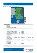
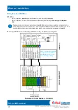
Page 22: ...Fine wire fuse 5 x 20 mm 400 mA inert F Connections Actuator board LED 1 Red 5V 2 Black Solenoid valve Valve 3 Red 24V 4 White Dosing pump Pump I 5 Red 24V 6 Black G Connections input contact Input f...

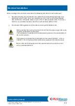
Page 23: ...collars To loosen a terminal use a slotted screwdriver SL with a maximum blade width of 3 mm The relevant VDE regulations must be observed during all installation work Before opening the housing disco...

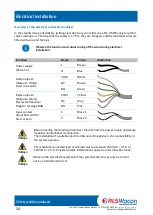
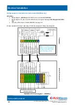
Page 24: ...n L Brown N Blue Relay output 1 Output 1 Water Limit value alarm COM White NC Brown NO Green Relay output 2 Output 2 Alarm Device malfunction Reagent message BoB COM Yellow NC Grey NO Pink Input conta...

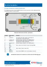
Page 25: ...r On off switch on the junction box 3 L power out Switched supply voltage for the LIMES analyser 4 N power in Connection for supply voltage with wiring for On off switch on the junction box 5 N power...

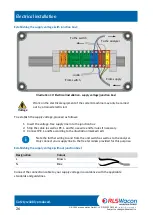
Page 26: ...ip the cable as well as PE L and N use wire end ferrules if necessary 3 Connect PE L and N according to the illustration marked red Note the further wiring to and from the unit switch as well as to th...

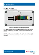
Page 27: ...nnection from COM to NO An indicator light or horn can be connected to relay output 1 to signal a limit violation If the limit value is exceeded relay output 1 remains switched in the position connect...

Page 28: ...d Power failure o The analyser is switched off relay output 2 has dropped out Reagent message o The content of the reagent bottle is below approx 10 Error zero sample no sufficient brightness before r...

Page 29: ...analysis interval No external voltage may be applied to the input contact For information regarding the wiring of the input contact see page 33 Information regarding the function of the input contact...

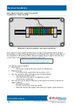
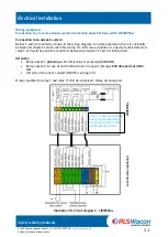
Page 30: ...1 picked up when limit value is exceeded COM NO Relay output 2 in case of unit malfunctions or reagent message BoB dropped out COM NC Circuitry of the input contact INPUT see page 33 Drawn position fo...

Page 31: ...this wiring If a limit value violation or a device fault is detected relay 1 or 2 switches and the continuity between terminals 11 and 6 is interrupted Attention Relay output 1 picked up when limit v...

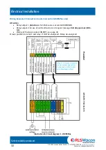
Page 32: ...ut 1 picked up when limit value is exceeded COM NO Relay output 2 in case of unit malfunctions or reagent message BoB dropped out COM NC Wiring of the input contact INPUT see page 33 Drawn position fo...

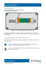
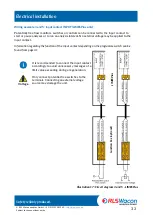
Page 33: ...n analysis interval No external voltage may be applied to the input contact Information regarding the function of the input contact depending on the programme switch can be found from page 41 It is re...

Page 34: ...The input contact function is not active on the LIMESBase Controls or switches connected to the input contact do not cause analyses to start or stop To enable the input contact function you need an u...

Page 35: ...can switch on the reagent pump e g to vent the hose line during commissioning The agitator runs simultaneously with the reagent pump Reset Functions Clear relay 1 if the limit value is exceeded Clear...

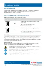
Page 36: ...e system is ready again after regeneration The analysis takes 3 minutes plus the set flush time A control measurement takes place 4 minutes after completion of the first measurement first value suppre...

Page 37: ...e stirring blade is stopped The actuator board LED lights up and the evaluation of the water sample takes place immediately The result of the measurement is displayed on the LEDs on the front of the u...

Page 38: ...correct reagent type is used for the application Check that the expiry date of the reagent has not expired Make sure that all water bearing parts are tight and that the inlet and outlet are connected...

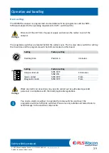
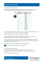
Page 39: ...r The 16 step rotary switch for setting the rinse time and the programme switches SW are located on this board Setting Factory setting Flushing time Position 6 4 minutes Setting Factory setting Analys...

Page 40: ...ne free and fresh water is analysed A long rinsing time also reduces build up in the measuring chamber The local conditions of a system can be very different different pipe cross sections to the softe...

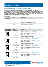
Page 41: ...Description Closed The input contact is permanently closed Open The input contact is permanently open Pulse Only one analysis is carried out Setting for the use of a switch or flow monitor Internal an...

Page 42: ...ow monitor This function is used if analyses are only to be carried out as soon as a water withdrawal takes place This is particularly useful for discontinuous operation i e filling up a storage tank...

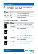
Page 43: ...e use of an external control depending on SW1 and SW2 switch position External analysis start input contact activated SW3 ON SW programme switch position INPUT Input contact Function For pulsed operat...

Page 44: ...er in the set interval The pausing of the analysis interval by the flow monitor is indicated by the yellow LED flashing If the flow monitor reports flowing water after a standstill period an analysis...

Page 45: ...prevents false alarms due to the counter ion effect after a system shutdown The LIMESBase and the LIMESPlus are factory equipped with a fixed activated first value suppression Trigger conditions for a...

Page 46: ...ied out yet When the input contact is open the yellow LED Input contact open also flashes Insert a full reagent bottle and reset reagent level Insert a full reagent bottle into the LIMES Press and hol...

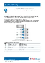
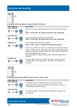
Page 47: ...unit status is indicated by 4 LEDs on the front of the unit The following indicators can be displayed during operation depending on the configuration The display variants of the blue LED reagent notes...

Page 48: ...e relay 1 position can however be deleted by pressing the Reset button in this case the relay drops out but the red LED A remains flashing The relay 1 position can be seen on the LED combination of LE...

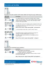
Page 49: ...be sufficient for unattended operation in the set analysis interval BoB over 72 hours Relay 2 Device fault reagent message BoB has dropped out To acknowledge the BoB alarm press the Reset button LED...

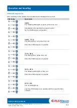
Page 50: ...value LED A flashing red and at the same time device malfunction LED D flashing red Signals that the preset limit value has been exceeded and that relay 1 is energised Relay 1 Limit value is energised...

Page 51: ...00 The following LEDs light up green yellow blue red Immediately after resetting the reagent counter Up to 10 000 analyses are possible 100 75 The LEDs light up red yellow blue red More than 7500 anal...

Page 52: ...the maintenance of the treatment plant or during a break in operation Before servicing switch off the unit by pressing the mains switch or disconnecting the supply voltage Depending on the wiring some...

Page 53: ...press and hold the Reagent button for 10 seconds to pump reagent from the newly inserted bottle into the measuring chamber and to press the air bubbles out of the tube The reagent bottle is not inclu...

Page 54: ...o 4x screws A2 M4 x 65 o 3x measuring chamber components o 1x plastic tube transparent o 2x O rings 24 x 2 5 o 2x inlet outlet screw connection o 2x O rings 9 x 1 6 o 1x injector o 1x O ring 5 28 x 1...

Page 55: ...measuring accuracy of the LIMES analyser the peristaltic pump cassette should be replaced after 24 months Press the locking tabs together with your thumb and index finger and pull the hose pump casse...

Page 56: ...valve you relax the supply line and the measuring chamber empties Hold a small container under the inlet and outlet Switch the unit off again Only when replacing the filter or pressure regulator Loos...

Page 57: ...d hold the Valve button until clear water flows out of the drain hose Observe the electrical connection according to the illustration on page 22 Exchange of the measuring chamber Preparation Ensure a...

Page 58: ...the main board Pull the hose pump cassette off the motor shaft Loosen the two screws on the front of the unit Replace the peristaltic pump motor Connect the new peristaltic pump motor according to th...

Page 59: ...e front cover open and the rubber cap removed All buttons and switches are operated When running the diagnostic programme please note the following Depending on the wiring the cables of relays 1 and 2...

Page 60: ...After switching on the unit diagnostic step 1 begins The LEDs light up one after the other Limit value undercut Exceeding the limit value Analysis active Lack of reagent Device fault Checking the but...

Page 61: ...F again one after the other each of the programme switches SW1 SW3 is assigned a combination of LED displays SW4 is not checked as it is already ON for diagnosis SW1 SW2 SW3 Checking the rotary switch...

Page 62: ...the connection cables with a continuity tester or a voltmeter depending on the wiring Checking the solenoid valve After pressing the Start key for the 6th time the solenoid valve is tested The yellow...

Page 63: ...lowing colour detection test After pressing the Start key for the 11th time the zero value of the optical path is measured with a colourless water sample The last 3 LEDs flash For testing the measurin...

Page 64: ...hardness because an undefined amount of reagent is dosed The Valve button can be used to flush the reagent out of the measuring chamber Exit diagnostic program After checking the unit functions switch...

Page 65: ...Safety reliably produced RLS Wacon analytics GmbH 49 0 5121 28126 0 info rls wacon de Subject to change without notice 65 Spare parts Illustration 22 Spare parts LIMES...

Page 66: ...nch 30 035 201 I Measuring chamber cpl LIMES 30 035 104 J Screw in connection 1 4 inch LIMES incl O ring 2x 30 055 203 K Measuring chamber tube LIMES incl O rings 30 055 204 L LIMES injector including...

Page 67: ...offered for this purpose It contains all the tools needed for cleaning as well as the cleaning fluid FIT 3000 For information on how to perform maintenance see from page 52 Article description Articl...

Page 68: ...035 205 LIMES connection set Contains the following items Reducing nipple Stainless steel 1 4408 V4A 1 2 inch to 1 4 inch Conical external thread Socket ball valve stainless steel 1 4408 V4A with 1 4...

Page 69: ...32 074 135 32 474 135 LHV 0 5 0 5 9 0 9 32 074 165 32 474 165 LHV 3 3 0 53 5 3 32 074 195 32 474 195 LHV 7 7 0 125 12 5 32 074 210 32 474 210 One bottle of reagent is sufficient for approx 10 000 limi...

Page 70: ...ed and connected Error in the zero sample Cause Measure There is no sample water in the measuring chamber Check the water inlet The reagent is not resolved Check whether there is an agitator blade in...

Page 71: ...Safety reliably produced RLS Wacon analytics GmbH 49 0 5121 28126 0 info rls wacon de Subject to change without notice 71 Notes...

Page 72: ...Safety reliably produced RLS Wacon analytics GmbH 49 0 5121 28126 0 info rls wacon de Subject to change without notice 72 Appendix Maintenance and service Date Employees Comment Model Serial number...

Page 73: ...in SW3 Input contact Off On SW4 Diagnostic mode Off On Position Rotary switch flushing time 0 1 2 3 4 5 6 7 8 9 A B C D E F 5 10 20 50 90 2 4 8 10 12 14 16 18 20 25 30 Sec Sec Sec Sec Sec Min Min Min...

Page 74: ...Safety reliably produced RLS Wacon analytics GmbH 49 0 5121 28126 0 info rls wacon de Subject to change without notice 74 EU Declaration of Conformity...

Page 75: ...Gropiusstr 12 D 31137 Hildesheim Phone 49 0 5121 28126 0 Fax 49 0 5121 28126 20 info rls wacon de www rls wacon de Managing Directors Dr Claudia Rudolph Dr Sascha Matern Register court Hildesheim Loc...

Page 76: ......
Reviews: