


RIX Industries
MAN-2PS2B-N2
Page 18
To adjust the 2nd stage piston clearance, use the following procedure:
1.
Remove the 2nd stage head per
Section 7.3
.
2.
While holding the cylinder firmly in place, rotate crankshaft to ensure piston is at Top Dead
Center (TDC).
3.
Measure the clearance between the piston and the top of the cylinder liner. The
spool/guide cylinder may be threaded in or out to achieve a piston to cylinder clearance of
.012" to .016".
4.
Reinstall the head per
Section 7.3
.
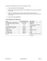
7.10
Clearances & Tolerances
Part
Nominal Dimension
Wear Limit
1
st
Stage Piston to Valve clearance
.011-.015”
Adjustable
2
nd
Stage Piston to Valve clearance
.012-.016”
Adjustable
Bearings
N/A
By inspection for knocking or
rough running.
Connecting Rod, Lower Bore
Ø3.146”
+.001”
Connecting Rod, Upper Bore
Ø0.687”
+.001”
Wrist Pin
Ø0.5000”
-.0005”
1
st
Stage Piston
Ø1.21”
Not a wearing part
1
st
Stage Cylinder
Ø1.251”
+.005”
2
nd
Stage Piston
Ø0.497”
-.003”
2
nd
Stage Cylinder
Ø0.501”
+.003”
Valves
-
Inspect for warping, scratches,
or pitting
Summary of Contents for 2PS-H-N2
Page 36: ...RIX Industries MAN 2PS2B N2 Page 28 FIGURE 1 COMPRESSOR CROSS SECTION FASTENER DETAIL...
Page 37: ...RIX Industries MAN 2PS2B N2 Page 29 FIGURE 2 COMPRESSOR CROSS SECTION PUMP DETAIL...
Page 38: ...RIX Industries MAN 2PS2B N2 Page 30 FIGURE 3 1ST STAGE VALVE DETAIL...
Page 39: ...RIX Industries MAN 2PS2B N2 Page 31 FIGURE 4 2ND STAGE VALVE DETAIL...
Page 40: ...RIX Industries MAN 2PS2B N2 Page 32 FIGURE 5 EXTERIOR FASTENER DETAIL...
Page 41: ...RIX Industries MAN 2PS2B N2 Page 33 FIGURE 6 MOTOR AND CONTROL BOX MOUNTING...
Page 42: ...RIX Industries MAN 2PS2B N2 Page 34 FIGURE 7 SUCTION PLUMBING DETAIL...
Page 43: ...RIX Industries MAN 2PS2B N2 Page 35 FIGURE 8 INTERSTAGE PLUMBING DETAIL...
Page 44: ...RIX Industries MAN 2PS2B N2 Page 36 FIGURE 9 FINAL DISCHARGE PLUMBING DETAIL...
Page 45: ...RIX Industries MAN 2PS2B N2 Page 37 FIGURE 10 COOLING FAN SUB ASSEMBLY DETAIL...
Page 46: ...RIX Industries MAN 2PS2B N2 Page 38 FIGURE 11 BELT INSTALLATION DETAIL...
Page 47: ...RIX Industries MAN 2PS2B N2 Page 39 FIGURE 12 GUARD MOUNTING DETAIL...
Page 48: ...RIX Industries MAN 2PS2B N2 Page 40 FIGURE 13 CONTROL BOX DETAIL 1 OF 2...
Page 49: ...RIX Industries MAN 2PS2B N2 Page 41 FIGURE 14 CONTROL BOX DETAIL 2 OF 2...
Page 50: ...RIX Industries MAN 2PS2B N2 Page 42 FIGURE 15 CONTROL BOX WIRING DIAGRAM...
Page 51: ...RIX Industries MAN 2PS2B N2 Page 43 FIGURE 16 ELECTRICAL SCHEMATIC...
Page 52: ...RIX Industries MAN 2PS2B N2 Page 44 FIGURE 17 FLOW SCHEMATIC...
Page 56: ......
Page 57: ......
Page 58: ......
Page 59: ......