


Page 14/ 24
34-81 10/2013
6. RELAY
OUTPUTS
6.1
OUTPUT SETUP AND SPECS
1. 3 relay outputs. SPST relay contacts going to spade terminals #4-9.
2. The outputs are rated at 3A, or 8A resistive load.
3. Each output (1-3) can be controlled via Modbus RTU Communication by setting
on
or
off
to the
1on
,
2on
,
3on
parameters.
4. Each output can be configured to operate as a control output, typically for temperature control. This is done when
1on
,
2on
,
3on
respectively are set to
rEG
. This is the default setting.
a.
1on
=
rEG
Output 1 is configured for Temperature Control (Same for
2on
,
3on
).
b.
1on
=
oFF
Output 1 is off.
c.
1on
=
on
Output 1 is on any time the TempTrac is enabled (Alarms will not disable). On power loss, this contact
will be open, and when the TempTrac displays OFF, this will contact will be open. This is no longer a control
output, and is not subject to alarms.
5. Output 1, Spade terminals 4 & 5.
6. Output 2, Spade terminals 6 & 7.
7. Output 3, Spade terminals 8 & 9.
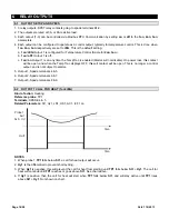
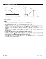
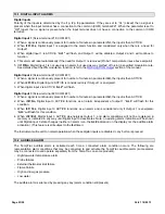
6.2
OUTPUT 1 CALL FOR HEAT (1on=rEG)
Kind of action
: Heating
Reference probe
: TP1
Terminals:
SPADE 4 & 5
Related Parameters:
St1, Hy1, LS1, US1, AC1, i3F, 1on
time
time
Out1
Probe1
Set1
Set1+ Hy1
NOTES
1. When probe 1
TP1
falls below
St1
, a call for heat output will occur.
2.
Hy1
is the differential to prevent short cycling.
3. When
Hy1
is negative, this will prevent the call for heat from starting until
TP1
falls below
St1
+
Hy1
. The call for
heat will continue until
TP1
reaches or goes above
St1
. See chart above.
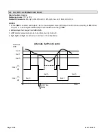
4. If
Hy1
is positive, then the call for heat will start when
TP1
falls below
St1
, and will stay active until
TP1
rises
above
St1
+
Hy1
. Not shown on chart.