


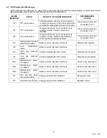
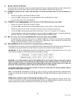
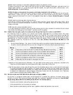


13
34-55 08/14
7 VENTING
7.1 Venting the unit using Category I, III or IV Venting Materials
The following instructions can be used to install the VT3 using UL, ULC, ETL or CSA listed, Category I, negative
pressure, non-condensing vent materials, like type B venting or it can be installed using smaller diameter UL, ULC,
ETL or CSA listed, stainless steel, Category III, positive pressure, non-condensing venting materials. UL, ULC, ETL
or CSA listed, stainless steel, Category IV, positive pressure, condensing ready venting materials can also be used
to substitute for the Category III venting materials.
Look at the main information decal attached near the front of the unit to determine whether the appliance is for
installation utilizing Category I venting only, Category III venting only or if the appliance is for installation utilizing
Category I, III or IV venting. Follow the instructions below for the specific Category of venting selected and that
appears on the main information decal. Once the Category is selected, follow only the instructions given for that
Category.
WARNING: Venting instructions for Category I (negative vent pressure) and Category III/IV (positive vent
pressure) must not be mixed. Mixing or following instructions for a different Category can cause inadequate
venting or allow carbon monoxide to enter an occupied space, resulting in property damage, personal injury
or death.
7.2 CATEGORY I VENTING
When properly installed with UL, ULC, ETL or CSA listed Category I venting, the appliance
operates with a non-
positive vent static pressure and with a vent gas temperature that
avoids excessive condensate production in the
vent.
Category I venting should terminate above the roof surface and must be installed in accordance with the "Venting of
Equipment" section of the current edition of the National Fuel Gas Code, ANSI Z223.1 / NFPA 54 or, in Canada, the
“Venting Systems and Air Supply for Appliances” section of the current edition of the CAN/CSA B149.1-10
Installation Codes, or applicable provisions of the local building codes.
•
Do not use the vent connection size to determine the necessary vent connector, vent or stack size. For proper
sizing use the National Fuel Gas Code “Fan-assisted” table.
•
Locate unit(s) as close as possible to the vent or stack. The vent connector from the appliance vent connection to
the vertical vent or stack that terminates outside and above the building roof must be made with listed Type “B”
double wall (or equivalent), must be as direct as possible and must have no blockage or reduction in diameter.
•
Support horizontal portions of the venting system to prevent sagging. Horizontal runs must slope upwards not less
than 1/4 inch per foot (21 mm/m) from the appliance to the vent terminal. Follow manufacturer’s instructions.
•
Do not attach the vent connector of any appliance vented by natural draft to any portion of a mechanical draft
system operating under positive pressure.
•
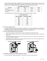
A barometric damper (draft control) is supplied with all models, unless the CAT34 option is ordered. If the boiler
was ordered with the CAT34 option, but is going to be installed with a Category I vent system, a barometric
damper and vent size increaser (for attachment of the vent connector to the boiler vent connection) sized to
match the required Category I vent diameter, must be obtained from Riverside Hydronics. Attach the properly
sized vent increaser to the boiler vent connection with three sheet metal screws. A properly installed and adjusted
barometric damper helps stabilize draft and regulate high updraft. Conventional vented multiple unit installations
with combined venting require barometric dampers to regulate draft at each unit. Adjust the barometric damper to
0.04 inches water column updraft, when used. Follow the barometric damper manufacturer’s installation
instructions.
•
The draft in vent should be within a range of -.02 and -.08” W.C.
•
A UL, ULC, ETL or CSA listed vent terminal, suitable for Category I products,
must
be installed to adequately
protect the gas vent from wind and weather.
•
The vent terminal must extend at least 3 ft (.09 m) above the highest point where it passes through the roof of a
building and at least 2 ft (.06 m) higher than any portion of a building within a horizontal distance of 10 ft. (3.0 m).
•
The vent cap must terminate at least 3 feet (0.91 m) above any forced air inlet within 10 feet (3.05 m); 4 feet (1.22
m) below, 4 feet (1.22 m) horizontally from or 1 foot (0.3 m) above any door, window or gravity air inlet to the
building; 1 foot (0.3 m) above grade, 1 foot (0.3 m) above the highest snow levels and must terminate at least 7
feet (2.13 m) above grade when located adjacent to public walkways or gathering areas.
•
The vent terminal must not be installed closer than 3 feet (0.91 m) from an inside corner of an L-shaped structure.