background image


RC3402(63IR)04-2014-B 

Quick Installation Guide 

This manual provides instructions for quick installation and basic configuration of your IP device. 

1. Part names and positions 


Make sure if the polarity is correct. Incorrect connection may 
cause malfunction or damage to the IP device. 


Caution

!

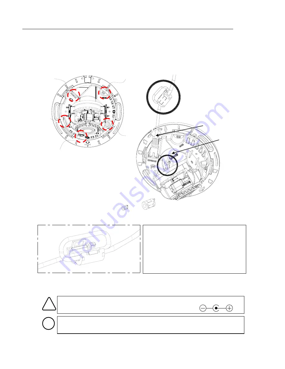
Power Adaptor Connector (DC 12V) 


* Model design and appearance are subject to change without any prior notice. 


LAN connector(POE supported) 


Reset button 


microSD/SDHC slot 


Power Cable connector(DC 12V) 


Video Output connector 
 

< Enlarged image of ferrite core clip open > 

< How to make a loop around the ferrite cores > 

1.


Open the ferrite core by lifting the clip. 

2.


Make one loop with the cable through the 
ferrite core. 

3.


Close the ferrite core to hold the cable loop 
into place.  

Installing the ferrite core on the cable is to suppress high frequency noise level  
in electronic singals. 

Note

i


IPN3402HD-6311

It is highly recommended to 

install the provided ferrite cores 
on the two cables respectively 
like the image around this text. 

Please also see <How to make a 
loop around the ferrite cores> 
below for more details. 


ZCAT1518-0730

ZCAT2132-1130

ZCAT1518-0730

ZCAT2132-1130

* The smaller ferrite core is for the MCX cable, and the bigger one is for the LAN cable. 

LAN cable 

MCX cable 

Summary of Contents for RC3402HD-6311IR

Page 1: ...f ferrite core clip open How to make a loop around the ferrite cores 1 Open the ferrite core by lifting the clip 2 Make one loop with the cable through the ferrite core 3 Close the ferrite core to hold the cable loop into place Installing the ferrite core on the cable is to suppress high frequency noise level in electronic singals Note i IPN3402HD 6311 It is highly recommended to install the provi...

Page 2: ...Place the installation template included in the package on the desired installation surface 2 Drill holes on correct spots based on the template paper and insert the anchor blocks into the holes 3 Remove the dome cover with the opener included in the package 4 Place the camera on the surface to match the alignment holes with the inserted anchor blocks 5 Tighten the screws into the anchor blocks 6 ...

Page 3: ...ide the dome 4 Adjust zoom and focus Once you are on the webpage go to Setup Video Audio Zoom Focus Then the features shown below will appear 1 Manual Focus Adjust zoom and focus by clicking arrow buttons the buttons move the lens more extensively than the buttons 2 Auto Focus Click One Click Focus to automatically set the lens Caution To adjust lens position rotate the camera gimbal To pan rotate...

Page 4: ...rk environment where IP address 192 168 XXX XXX are used users may view the live streaming images on a web page using the device s default IP address 1 Convert the device s MAC address to the IP address Refer to the Hexadecimal Decimal Conversion Chart at the end of the manual The MAC address of the device is attached on the side or bottom of the device 2 Start the Microsoft Internet Explorer web ...

Page 5: ...ormation under Local Network information displays the user PC s network area information Those information need to be incorporated to the IP Address Subnet Mask Gateway and DNS boxes except the last 2 sets of IP Address which are to be the unique numbers for the device Refer to the image above for the setting 4 Click Setup to complete the modification 5 Enter the user name and the password and the...

Page 6: ...ribed above are from Windows 7 Internet Explorer 9 environment 7 SETUP page To set up the device configuration 1 Click Setup on the upper left of the web page The login page is displayed as below 2 Enter the user name and the password and then select OK The default username and password are root and pass To learn how to set up the web page for advanced configuration refer to the Web Page User s Ma...

Page 7: ...Your device will get restarted with safe mode when the device does not completely boot certain times The errors are mainly caused by these two factors power source unplugged or damage occurred on firmware file during the system boot The messages like below will appear on the webpage when your device has been rebooted in safe mode Then you should follow the instructions on the webpage according to ...

Page 8: ...3 51 58 88 7D 125 A2 162 C7 199 EC 236 0F 15 34 52 59 89 7E 126 A3 163 C8 200 ED 237 10 16 35 53 5A 90 7F 127 A4 164 C9 201 EE 238 11 17 36 54 5B 91 80 128 A5 165 CA 202 EF 239 12 18 37 55 5C 92 81 129 A6 166 CB 203 F0 240 13 19 38 56 5D 93 82 130 A7 167 CC 204 F1 241 14 20 39 57 5E 94 83 131 A8 168 CD 205 F2 242 15 21 3A 58 5F 95 84 132 A9 169 CE 206 F3 243 16 22 3B 59 60 96 85 133 AA 170 CF 207 ...

Reviews: