4 Assembly and connection
Rittal cooling unit assembly and operating instructions
7
EN
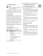
3.1.8 Additional interface X3
An additional interface card may be connected to
the 9-pole SUB-D connector X3 in order to incorpo-
rate the cooling unit into higher-level monitoring
systems (available as an accessory, interface card
Model No. SK 3124.200).
3.2 Proper usage
Rittal enclosure cooling units were developed and
designed in accordance with the state-of-the-art and
the recognised rules governing technical safety.
Nevertheless, if used improperly, they may pose a
threat to life and limb or cause damage to property.
The unit is only intended for cooling enclosures. Any
other use is deemed improper. The manufacturer will
not be liable for any damages caused as a result of
improper use, or for incorrect assembly, installation
or use. All risk is borne solely by the user.
Proper usage also includes the observation of all
valid documents and compliance with the inspection
and servicing conditions.
3.3 Scope of supply
The unit is supplied in a packaging unit in a fully
assembled state.
Please check the delivery for completeness:
Tab. 1: Scope of supply
4
Assembly and connection
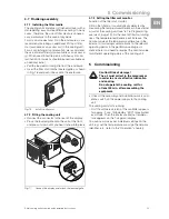
4.1 Choosing the installation site
When choosing the installation site for the enclosure,
please observe the following:
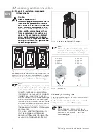
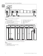
– The site for the enclosure, and hence the arrange-
ment of the cooling unit, must be carefully selected
so as to ensure good ventilation. Depending on the
siting of the unit, if several units are installed direct-
ly adjacent to one another, the distance from the
wall must be at least 200 mm.
– The cooling unit must be installed and operated in
a vertical position (maximum deviation: 2°).
– The site must be free from excessive dirt and
moisture.
– The ambient temperature must not exceed 55°C.
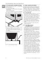
– It must be possible to fit a condensate discharge
(see “4.4 Connecting the condensate discharge”,
page 10).
– The mains connection data as stated on the rating
plate of the unit must be guaranteed.
4.2 Assembly instructions
4.2.1 General
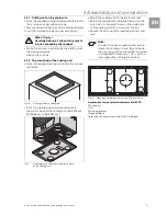
– Check the packaging carefully for signs of damage.
Traces of oil on damaged packaging are an indi-
cation of refrigerant loss and leakages. Packaging
damage may be the cause of a subsequent func-
tional failure.
– The enclosure must be sealed on all sides (IP 54).
Increased condensation will occur if the enclosure
is not airtight.
– In order to avoid excessive condensation inside
the enclosure, we recommend installing a door
limit switch (e.g. PS 4127.0
1
0) which deactivates
the cooling unit when the enclosure door is opened
(see “3.1.7 Door limit switch”, page 6).
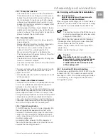
Note:
The electrical signals at the interface are
of an extra-low voltage (not extra-low safety
voltages to EN 60 335).
Qty.
Description
1
Enclosure cooling unit
1
1
1
1
1
1
1
1
Dispatch bag:
– Sealing plate (SK 3273.xxx, SK 3383.xxx
to SK 3387.xxx)
– Sealing frame
– Plug-in terminal strip
– Assembly and installation instructions
– Assembly, installation and operating
instructions on CD-ROM
– Declaration of conformity
– Safety notes
1
Drilling template
Summary of Contents for SK 3273.xxx
Page 2: ......


