Rinstrum D841 Installation Manual Download Page 8

D841/D850 Installation Manual 


Page 8 


008D-600-150 

Install it onto your PC; connect your PC and the Remote to the same network. Do a 
broadcast  search  using  the  Lantronix  Device  Installer  to  find  the  display  on  the 
network. Use the MAC address located on the serial number label of the display. 

Select the correct device and click "Assign IP". Enter in a valid IP address within the 
allowable  range  of  the  network  and  select  "Assign".  New  IP  address  will  be 
assigned to the device. When complete the device will be shown on table with new 
IP  address  and  status  "Online".  For  further  information  use  the  Help  within  the 
software. 

Data to be displayed is sent as Serial over Ethernet, so any supported protocols can 
used for the data format. 

Note: 

The  display  listens  on  port  10001.  Use  this  port  with  the  assigned  IP  to 

connect to the display.


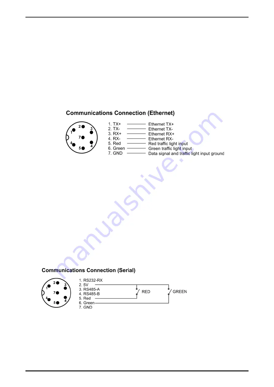
Figure 9 - Ethernet socket connections 

2.5. 

Traffic Light Control (D841) 

The traffic lights can be controlled by a control character in the supported protocols 
(refer  Appendix  A  for  supported  protocols)  or  by  digital  inputs  available  on  the 
communication connection socket. If the traffic light is set by serial  communication, 
the digital input control of the traffic lights will be ignored until the power is cycled. 

Note:

  D850  does  not  have  dedicated  traffic  lights  but  will  display  "STOP"  for  Red, 

"GO" for Green and "------" for both Red and Green inputs. 

2.5.1.  From  Internal  5V  DC  Source  (Serial  communications  connection  variant 

only) 

For  remote  operation  of  the  traffic  lights  it  is  recommend  using  a  twisted  pair  multi 
core cable with one pair for the data and another two pairs for the traffic light control 
to minimise interference. The switch contact will short the 5V on pin 2 to either pin 5 
for RED and/or pin 6 for GREEN as per the diagram below. 


Figure 10 - Driving traffic lights from internal 5VDC source 


2.5.2.  From an External DC Source (Serial and Ethernet communications variants) 

To control the traffic lights from a remote DC power supply the following connections 
are required. It is recommend using a twisted pair multi core cable with one pair for 
the  data  and  another  two  pairs  for  the  traffic  light  control  to  minimise  interference. 
The  DC  power  supply  0VDC  needs  to  be  connected  to  pin  7  GND  on  the 

Summary of Contents for D841

Page 1: ... 6 2 4 3 Ethernet Optional 7 2 5 Traffic Light Control D841 8 2 5 1 From Internal 5V DC Source Serial communications connection variant only 8 2 5 2 From an External DC Source Serial and Ethernet communications variants 8 2 6 Setup Command 9 2 6 1 Sending the Setup Command 11 2 7 Scrolling Messages K802 firmware in D841 Only 12 2 8 Mounting Options 12 2 8 1 Wall Mounting 12 2 8 2 Weather Hood Opti...

Page 2: ...feet at 120 degrees viewing angle Update Rate Dependent on data update rate Operating Environment Temperature 20 to 60 C 4 to 140 F case temperature Humidity 90 RH non condensing Storage 20 to 60 C 4 to 140 F ambient Digital Setup Automatic detection with adjustment via a command string Memory Full non volatile operation Dimensions External Dimensions L x H x D D841 760mm x 150mm x 80mm 30 x 6 x 3...

Page 3: ...sing labels Symbol Name Description ZERO Indicated when the indicator is displaying Centre Of Zero NET Indicated when the indicator shows NET weight MOTION Indicated when the indicator reading is not stable Brightness Control Adjustable 10 steps and Auto Detect Full Brightness Default Scrolling Messages Available in D841 only using K802 Factory fit Firmware up to 150 characters at slow medium fast...

Page 4: ...d The complete annunciator section can also be left or right hand justified of the weight string The serial interface supports RS 232 and RS 485 as standard with an Ethernet option also available Facilities for automatic selection of data source and baud rate are also standard The remote displays are individually addressable which allows a single device to send targeted information to multiple dis...

Page 5: ... seals are broken All connections are made at the external sockets located on the bottom right hand side Ensure power cable is not connected to a live source before terminating the power connector Make sure the environment is dry when terminating to prevent moisture ingress into sealed connectors Disconnect power before opening cable connector 2 3 Power Connection The D841 and D850 remote displays...

Page 6: ...hould ideally be connected to earth at one end for each of the communications options below As there is no provision for the shield connection at the communications connection end of the display it is recommended the shield be terminated at the indicator source end Figure 5 Shield Earthing 2 4 2 Serial Connection The serial connection is used to transmit data to the remote display A shielded data ...

Page 7: ...ng cable runs Multi dropping is supported A 120Ω resistor is provided for termination Recommended maximum cable distance for RS485 is 1 200m Figure 8 RS485 Socket connection 2 4 3 Ethernet Optional Confirm the display has the Ethernet option fitted by taking note of the connection label located on the underside near the data input socket The optional Ethernet connection has DHCP enabled by default...

Page 8: ...d protocols or by digital inputs available on the communication connection socket If the traffic light is set by serial communication the digital input control of the traffic lights will be ignored until the power is cycled Note D850 does not have dedicated traffic lights but will display STOP for Red GO for Green and for both Red and Green inputs 2 5 1 From Internal 5V DC Source Serial communicat...

Page 9: ...oftware that only send a single string with new data when required the Auto Protocol detect may not display all messages sent To overcome this you can lock the protocol using the configuration string which will force the unit not to search on start up but display first message received The display will try and display all data received when in a locked state even if the protocol does not match Che...

Page 10: ...Annunciator position 0x30 Left hand annunciators Default 0x30 0x31 Right hand annunciators K801 only 0x32 Left hand with units 0x33 Right hand with units Address Hi MSB of the address value Default 0x30 0 to 9 0x30 to 0x39 Address Lo LSB of the address value Default 0x31 0 to 9 0x30 to 0x39 Time Out Hi MSB of the Time out value in seconds Default 0x30 0 to 9 0x30 to 0x39 Time Out Lo LSB of the Tim...

Page 11: ...d protocol first to acknowledge the previous changes Send the Reset String via the software or R400 indicator until Display will show OK then reinitialize at default settings Note if the unit is already at default settings then the OK message will not be shown Determine what settings need to be changed as based on the Configuration String Set the suitable options in the software or create a custom...

Page 12: ...ts provided The outer mounting holes are 8mm in diameter Figure 12 Mounting brackets and optional weather hood 2 8 1 Wall Mounting For wall mounting it is recommended that 6mm or 1 4 bolts and washers be used as a minimum Both Brackets are to be used with mounting hole centres at 250mm 9 8 wide and 200mm 7 9 high Fit top bolts first to support display 2 8 2 Weather Hood Optional The optional weath...

Page 13: ...Manual 008D 600 150 Page 13 2 8 3 Mounting Plate Optional D841 only The optional mounting plate for the D841 supports VESA RAM and pole mounting Figure 13 VESA RAM and Pole mounting examples Figure 14 Optional mounting plate ...

Page 14: ... status Check source device ERROR Error The source device is reporting an error in its status as detected in the protocol Check source device No valid data from indicator and unit has timed out Check serial Ethernet input check cables and connections confirm protocol baud data bits are supported then power cycle remote to reset PR 00 If this is being intermittently displayed after the start up seq...

Page 15: ...ry L105 8 Gedge C2 No No No Gedge 9 Gedge C3 No No No Gedge 10 A D standard string No Yes No A D 11 AD4531 No No No A D 12 Toledo continuous No Yes Yes Toledo 13 GSE without COZ No Yes Yes GSE 14 GSE with COZ No Yes Yes GSE 15 Schenck without DP No No No Schenck 16 Schenck with DP No No No Schenck 17 Auto control string 1 No No No Auto control PC Software 18 Auto control string 2 No No No Auto con...

Page 16: ...D841 D850 Installation Manual Page 16 008D 600 150 Notes ...

Page 17: ...D841 D850 Installation Manual 008D 600 150 Page 17 Notes ...

Reviews: